Electric multi-turn actuators
SA 07.1 – SA 30.1
SAR 07.1 – SAR 30.1
with actuator controls
AUMA MATIC AM 01.1 / AM 02.1
for flange type FA
Table of contents
Page1. Safety instructions 4
1.1 Range of application 4
1.2 Electrical connection 4
1.3 Maintenance 4
1.4 Warnings and notes 4
2. Short description 5
3. Technical data 6
4. Additional information to the wiring diagram legend 9
5. Transport, storage and packaging 10
5.1 Transport 10
5.2 Storage 10
5.3 Packaging 11
6. Mounting to valve/ gearbox 12
7. Mounting positions of the local controls 14
8. Electrical connection 15
8.1 Connection with AUMA plug/ socket connector (S, SH, SE) 17
9. Manual operation 19
10. Operation and indications of the local controls 20
11. Opening the switch compartment 22
11.1 Removing the cover from the switch compartment 22
11.2 Pulling off the indicator disc (option) 22
12. Setting the limit switching 23
12.1 Setting end position CLOSED (black section) 23
12.2 Setting end position OPEN (white section) 23
12.3 Checking the limit switches 23
13. Setting the DUO limit switching (option) 24
13.1 Setting direction CLOSE (black section) 24
13.2 Setting direction OPEN (white section) 24
13.3 Checking the DUO limit switches 24
14. Setting the torque switching 25
14.1 Setting 25
14.2 Checking the torque switches 25
15. Test run 26
15.1 Checking the direction of rotation 26
15.2 Checking the setting of the limit switching 27
15.3 Checking the type of seating 27
15.4 Checking the PTC tripping device (option) 27
16. Setting the potentiometer (option) 29
Scope of these instructions: These instructions valid for multi-turn actuators of the type range SA 07.1 – SA 30.1/ SAR 07.1 – SAR 30.1 with
the actuator controls AM 01.1 / AM 02.1.
These operation instructions are only valid for “clockwise closing”, i.e. driven shaft turns clockwise to close the valve.
Page 17. Setting the electronic position transmitter RWG (option) 30
17.1 Setting 2-wire system 4 – 20 mA and 3- /4-wire system 0 – 20 mA 31
17.2 Setting 3- / 4- wire system 4 – 20 mA 32
18. Setting the mechanical position indicator (option) 33
19. Closing the switch compartment 33
20. Actuator controls AUMA MATIC 34
20.1 Functions of the diagnosis LEDs on the interface board (standard version) 34
20.2 Programming the logic board 35
20.3 EMERGENCY - OPEN and EMERGENCY - CLOSE signal (option) 36
21. Electronic positioner (option) 37
21.1 Technical data 37
21.2 Setting 37
21.2.1 Setting type of signal 39
21.2.2 Setting actuator behavior on loss of signal 40
21.3 Positioner adjustment for end position CLOSED (standard version) 41
21.4 Positioner adjustment for end position OPEN (standard version) 43
21.5 Setting the sensitivity 43
21.6 Positioner adjustment for end position OPEN (inverse operation) 45
21.7 Positioner adjustment end position CLOSED (inverse operation) 46
21.8 Positioner in Split Range version (option) 47
21.8.1 Split Range: description of functions 47
21.8.2 Programming 47
21.8.3 Positioner adjustment for Split Range 47
22. Timer (option) 49
22.1 Functions of the diagnosis LEDs (timer) 49
22.2 Setting start and end of stepping mode via DUO limit switching (option) 50
22.3 Setting ON and OFF times 51
23. Fuses 52
23.1 Fuses within the actuator controls 52
23.2 Motor protection 54
24. Enclosure protection IP 68 (option) 55
25. Maintenance 56
26. Lubrication 56
27. Disposal and recycling 56
28. Service 57
29. Spare parts list Multi-turn actuator SA(R) 07.1 – SA(R) 16.1 60
30. Spare parts list controls AUMA MATIC 62
Index 63
1.
Safety instructions
1.1 Range of application
AUMA actuators are designed for the operation of industrial valves, e.g. globe valves, gate valves, butterfly valves and ball valves.
For other applications, please consult us. The manufacturer is not liable for any possible damage resulting from use in other than the designated applications. Such risk lies entirely with the user.
Observance of these operation instructions is considered as part of the con-trols’/ actuator’s designated use.
1.2 Electrical connection
During electrical operation, certain parts inevitably carry lethal voltages. Work on the electrical system or equipment must only be carried out by a skilled elec-trician themselves or by specially instructed personnel under the control and supervision of such an electrician and in accordance with the applicable electri-cal engineering rules.
1.3 Maintenance
The maintenance instructions (refer to page 56) must be observed, otherwise a safe operation of the actuator is no longer guaranteed.
1.4 Warnings and notes
Failure to observe the warnings and notes may lead to serious injuries or dam-age. Qualified personnel must be thoroughly familiar with all warnings and notes in these operation instructions.
Correct transport, proper storage, mounting and installation, as well as careful commissioning are essential to ensure a trouble-free and safe operation. During operation, the multi-turn actuator warms up and surface temperatures > 140 °F may occur. Check the surface temperature prior to contact in order to avoid burns.
The following references draw special attention to safety-relevant procedures in these operation instructions. Each is marked by the appropriate pictograph.
This pictograph means: Note!
“Note” marks activities or procedures which have major influence on the correct operation. Non-observance of these notes may lead to consequential damage.
This pictograph means: Electrostatically endangered parts!
If this pictograph is attached to a printed circuit board, it contains parts which may be damaged or destroyed by electrostatic discharges. If the boards need to be touched during setting, measurement, or for exchange, it must be assured that immediately before a discharge through contact with a grounded metallic surface (e.g. the housing) has taken place.
This pictograph means: Warning!
“Warning” marks activities or procedures which, if not carried out correctly, can affect the safety of persons or material.
2.
Short description
AUMA multi-turn actuators of the type range SA 07.1 – SA 30.1/SAR 07.1 – SAR 30.1 are driven by an electric motor and controlled by the actuator con-trols AUMA MATIC AM 01.1/ AM 02.1, which is included in the scope of delivery. A handwheel is provided for manual operation.
The limitation of travel is realized via limit switches in both end positions. Torque seating is also possible in both end positions. The type of seating is determined by the valve manufacturer.
Both the multi-turn actuator and the controls have a modular design, i.e. they are designed in accordance with the principle of a modular construction system. This means that each actuator or each controls are individually manufactured and combined for a specific valve automation task. An order-specific commis-sion number, printed on the name plate, is assigned to each actuator/ controls.
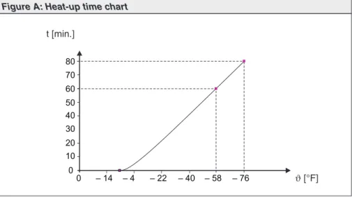
Commissioning
Please note that for low temperature versions (– 58 °F), the controls requires a heat-up time.
This heat-up time is applicable in case the actuator and the controls are not live and have cooled down to ambient temperature. In case commissioning has to be performed under these conditions, the following heat-up times have to be observed: 60 min. at – 58 °F 80 min. at – 76 °F 0 10 20 30 40 50 0 – 14 – 4 – 22 – 40 – 76 60 70 80 – 58 t [min.] ϑ[°F]
3.
Technical data
Features and functionsType of duty1) Standard: SA Short time duty S2 - 15 min
SAR Intermittent duty S4 - 25 % Option: SA Short time duty S2 - 30 min
SAR Intermittent duty S4 - 50 % Intermittent duty S5 – 25 %
Motors Standard: 3-ph AC asynchronous motor, type IM B9 according to IEC 34 Option: Special motors
Insulation class Standard: F, tropicalized Option: H, tropicalized Motor protection Standard: Thermoswitches (NC)
Option: PTC thermistors (according to DIN 44082) Self-locking Yes, for output speeds from 5.6 to 108 rpm
Limit switching Counter gear mechanism for end positions CLOSED and OPEN for 1 to 500 turns per stroke (optional for 1 to 5,000 turns per stroke) Standard: Tandem switch (2 NC and 2 NO) for each end position Options: Single switch (1 NC and 1 NO) for each end position,
switches galvanically isolated
Triple switch (3 NC and 3 NO) for each end position, switches galvanically isolated
Intermediate position switch (DUO limit switching), adjustable for any intermediate position
Torque switching Infinitely adjustable torque switching for direction OPEN and CLOSE Standard: Single switch (1 NC and 1 NO) for each direction
Options: Tandem switch (2 NC and 2 NO) for each direction, switches galvanically isolated Position feedback signal,
analogue (options)
Potentiometer or 0/4 – 20 mA (RWG) For further details, see separate data sheet Mechanical position indicator
(option)
Continuous indication, adjustable indicator disc with symbols OPEN and CLOSED Running indication (option) Blinker transmitter
Heater in switch compartment Standard: Resistance type heater with 5 W, 24 V DC Options: Self-regulating PTC heater, 5 – 20 W
24 – 48 V AC/DC, 110 – 250 V AC/DC or 380 – 400 V AC Motor heater (option) SA(R) 07.1 – 10.1: 12.5 W
SA(R) 14.1 – 16.1: 25 W SA(R) 25.1 – 30.1: 50 W
Manual operation Manual drive for setting and emergency operation, handwheel does not rotate during electrical operation. Option: Handwheel lockable
Connection to controls AUMA plug/ socket connector with screw type connection Output drive types A, B1, B2, B3, B4 according to EN ISO 5210
A, B, D, E according to DIN 3210 C according to DIN 3338
Special output drives: AF, AK, AG, IB1, IB3 Power supply, mains frequency
and current consumption
For mains voltage and mains frequency, refer to name plates at the controls and the motor Permissible variation of the nominal voltage: ± 10 %
Permissible variation of the mains frequency: ± 5 % Motor current consumption: Refer to motor name plate
Current consumption of the controls depending on the mains voltage: 100 to 120 V AC = max. 600 mA
208 to 240 V AC = max. 300 mA 380 to 500 V AC = max. 150 mA External supply of the
electronics (option)
24 V DC + 20 % / – 15 %,
Observe current consumption of the controls Rated power Refer to motor name plate
Note: The controls is designed for the rated power of the actuator Overvoltage category Category III
Switchgear Standard: Reversing contactors2)(mechanically and electrically interlocked)
for motor power up to 1.5 kW
Options: Reversing contactors2)(mechanically and electrically interlocked)
for nominal motor current up to 18 A (OPEN - CLOSE- duty) or 16 A (modulating duty)
Thyristor unit3)(recommended for modulating actuators)
for motor power up to 1.5 kW, 500 V AC with internal fuses for motor power up to 5.5 kW, 500 V AC, external fuses required Control Standard: Control inputs 115 V AC, OPEN - STOP - CLOSE (via opto-isolator,
with one common), current consumption: approx. 10 mA per input Observe min. duration of impulse for modulating actuators
Option: Control inputs 24 V DC, OPEN - STOP - CLOSE (via opto-isolator, with one common), current consumption: approx. 15 mA per input Output signals Standard: 5 output relays with gold-plated contacts:
4 potential-free NO contacts with one common: max. 250 V AC, 0.5 A (resistive load) Standard configuration:
End position OPEN, end position CLOSED, selector switch REMOTE, selector switch LOCAL
1 potential-free change-over contact, max. 250 V AC, 0.5A (resistive load) for collective fault signal
Standard configuration:
Torque fault, phase failure, motor protection tripped Option: Signals in connection with positioner:
End position OPEN, end position CLOSED (requires tandem switch within actuator)
Selector switch REMOTE, selector switch LOCAL via 2ndlevel
selector switch
1 potential-free change-over contact, max. 250 V AC, 0.5A (resistive load) for collective fault signal:
Torque fault, phase failure, motor protection tripped
Voltage output Standard: Auxiliary voltage 115 V AC, max. 30 mA for supply of the control inputs,3),
galvanically isolated from internal voltage supply
Option: Auxiliary voltage 24 V DC, max. 50 mA for supply of the control inputs, galvanically isolated from internal voltage supply
Local controls Standard: Selector switch LOCAL - OFF - REMOTE (lockable in all three positions) Push buttons OPEN - STOP - CLOSE
3 indication lights:
End position CLOSED (red), collective fault signal (yellow), end position OPEN (green) Option: Protection cover, lockable
Functions Standard: Switch-off mode adjustable
Limit or torque seating for end position OPEN and end position CLOSED Overload protection against excessive torques over the whole travel Excessive torque (torque fault) can be excluded from collective fault signal Phase failure monitoring with automatic phase correction
Push-to-run operation or self-retaining in REMOTE Push-to-run operation or self-retaining in LOCAL
Blinker transmitter signal of actuator can be switched on or off (option) Options: Positioner4):
Nominal position value via analogue input E1 = 0/4 – 20 mA Adjustable behavior on loss of signal
Adjustable sensitivity (dead band) and pause time Split Range operation
Motor protection evaluation Standard: Monitoring of the motor temperature in combination with thermoswitches in the actuator motor
Options: Additional thermal overload relay in the controls in combination with thermoswitches within the actuator
PTC tripping device in combination with PTC thermistors in the actuator motor Electrical connection Standard: AUMA plug/ socket connector with screw type connection
Options: Parking frame for wall mounting of the disconnected plug Protection cover for plug compartment (when plug is removed)
Threads for cable glands Standard: NPT-threads
Options: Pg-threads, G-threads
Wiring diagram Wiring diagram according to commission number included in delivery
Further options for version with RWG in the actuator
Position feedback (option) Analogue output E2 = 0/4 – 20 mA (load max. 500Ω)
Service conditions
Enclosure protection according
to EN 60 5295) Standard:Options: IP 67IP 68
IP 67-DS (Double Sealed) IP 68-DS (Double Sealed)
(Double Sealed = additional protection of the interior of the housing against ingress of dust and dirt when removing the plug)
Corrosion protection Standard: KN Suitable for installation in industrial units, in water or power plants with a low pollutant concentration
Options: KS Suitable for installation in occasionally or permanently aggressive atmosphere with a moderate pollutant concentration
(e.g. in wastewater treatment plants, chemical industry) KX Suitable for installation in extremely aggressive atmosphere
with high humidity and high pollutant concentration KX-G Same as KX, however aluminium-free version (outer parts) Finish coating Standard: Two-component iron-mica combination
Standard color Standard: AUMA silver-grey (similar to RAL 7037) Option: Other colors are possible on request Ambient temperature Standard: SA: – 25 °C to + 70 °C
SAR: – 25 °C to + 60 °C
Options: – 40 °C to + 60 °C/ – 40 to 140 °F, low temperature version
– 50 °C to + 60 °C/ – 75 to 140 °F, extreme low temperature version incl. heating system
– 60 °C to + 60 °C/ – 75 to 140 °F, extreme low temperature version incl. heating system
Vibration resistance according to IEC 60 068-2-6
1 g, from 10 Hz to 200 Hz
Resistant to vibrations during start-up or for failures of the plant. However, a fatigue strength may not be derived from this.
Applies to actuator with actuator controls, not valid in combination with gearboxes Lifetime SA 07.1 – 10.1: 20,000 operations (OPEN - CLOSE - OPEN) with 30 turns per stroke
SA 14.1 – 16.1: 15,000 operations (OPEN - CLOSE - OPEN) with 30 turns per stroke SA 25.1 – 30.1: 10,000 operations (OPEN - CLOSE - OPEN) with 30 turns per stroke SAR 07.1 – 10.1: 5 million operations/ starts6)
SAR 14.1 – 16.1: 3.5 million operations/ starts6)
SAR 25.1 – 30.1: 2.5 million operations/ starts6)
Weight Multi-turn actuator: Refer to Technical data SA/ SAR
Actuator controls: Approx. 7 kg (including AUMA plug/ socket connector)
Accessories
Wall bracket7) AUMA MATIC mounted separately from the actuator, including plug/ socket connector.
Connecting cables on request.
Recommended for high ambient temperatures, difficult access, or in case of heavy vibrations during service.
Further information
Reference documents Product description “Electric multi-turn actuators SA/ SAR” Product description “Actuator controls AUMA MATIC”
Dimension sheets SA/ SAR “...with integral controls AUMA MATIC” Technical data sheets AM 01.1/AM 02.1
Technical data sheets SA/ SAR Electrical data sheets SA/ SAR
5) For 3-phase asynchronous motors in enclosure protection IP 68, higher corrosion protection KS or KX is strongly recommended. Additionally, for enclosure protection IP 68, we recommend to use the double sealed terminal compartment DS. For special motors, the enclosure protection according to the name plate applies
6) The lifetime of modulating actuators depends on the load and the number of starts. A high starting frequency will rarely improve the modulating accuracy. To reach the longest possible maintenance and fault-free operation time, the number of starts per hour chosen should be as low as permissible for the process
7) Cable length between actuator and AUMA MATIC max. 100 m. Not suitable for version with potentiometer in the actuator. Instead of the potentiometer, an RWG has to be used in the actuator
4.
Additional information to the wiring diagram legend
Information A:
A running indication is possible if blinker transmitter (S5) is installed (opening and closing of contacts).
Direction CLOSE: Connections XK6 - XK7
Direction OPEN: Connections XK6 - XK8
Contacts remain closed in end position.
When connected to an external PLC, the blinking signal can be switched off via the DIP-switches (table 4, page 35).
Information B:
The type of seating in the end positions is determined by the valve manufac-turer. The setting is done at the programming switches S1-2 and S3-2 (see page 35). The tripping of a torque switch in an intermediate position switches off the actuator and causes a fault signal.
The limit switches serve for signalization when switching off by torque seating. They need to be set so that the appropriate switch is tripped shortly before reaching the end position. If the torque switch trips before the limit switch, the actuator is switched off and a fault signal is generated.
For further programming possibilities, e.g. self-retaining in operation mode REMOTE, see table 4, page 35.
Information D:
The following faults are registered and can be transmitted to the control room as a potential-free collective fault signal:
- Power failure - Phase failure
- Motor protection tripped
- Torque switch tripped in mid-travel.
This signal can be switched off on the logic board, see table 4, page 35.
Information E:
Input signals according to DIN 19 240.
The nominal operation current of inputs XK2, XK3, and XK4 amounts to
10 – 15 mA. If the internal voltage 24 V DC is used for remote control, it must only be connected via potential-free contacts.
Information F:
In case of wrong phase sequence, the running direction is automatically adjusted. In case of a phase failure, the actuator stops. The fault is indicated at LED V14 on the interface board (see page 34). For collective fault signal, see information D.
Information G:
Potential-free contacts are available for signals. The internal control voltage (XK11 / + 24 V and XK5 / – 24V) must not be used for external lamps, relays,
etc.
5.
Transport, storage and packaging
5.1 Transport
.
For transport to place of installation, use sturdy packaging..
Do not attach ropes or hooks to the handwheel for the purpose of lifting by hoist..
If multi-turn actuator is mounted on valve, attach ropes or hooks for the pur-pose of lifting by hoist to valve and not to multi-turn actuator.Fitting the handwheel:
For transport purposes, handwheels from a diameter of 400 mm are supplied separately.
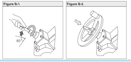
Engage manual operation prior to mounting the handwheel! If the manual operation is not engaged, damage can occur at the change-over mechanism.
.
Engage manual operation (figure B-1):Manually lift the red change-over lever while slightly turning the shaft back and forth until manual operation engages. The manual operation is correctly engaged if the change-over lever can be lifted by approx. 85°.
Manual force is sufficient for operating the change-over lever. It is not necessary to use an extension. Excessive force may damage the change-over mechanism.
.
Install handwheel over the red change-over lever on to the shaft (figure B-1)..
Release change-over lever (should snap back into initial position by spring action, figure B), if necessary, push it back manually..
Secure handwheel using the snapring supplied.5.2 Storage
.
Store in well-ventilated, dry room..
Protect against floor dampness by storage on a shelf or on a wooden pallet..
Cover to protect against dust and dirt..
Apply suitable corrosion protection agent to uncoated surfaces.If multi-turn actuators are to be stored for a long time (more than 6 months), the following points must be observed additionally:
.
Prior to storage: Protect uncoated surfaces, in particular the output drive parts and mounting surface, with long-term corrosion protection agent..
Check for corrosion approximately every 6 months. If first signs of corrosion show, apply new corrosion protection.After mounting, connect actuator immediately to electrical system, so that the heater prevents condensation.
85°
5.3 Packaging
Our products are protected by special packaging for the transport ex works. The packaging consists of environmentally friendly materials which can easily be separated and recycled.
We use the following packaging materials: wood, cardboard, paper, and Poly-urethane foam. For the disposal of the packaging material, we recommend recy-cling and collection centers.
6.
Mounting to valve/ gearbox
.
Prior to mounting the multi-turn actuator must be checked for damage. Damaged parts must be replaced by original spare parts..
After mounting to valve/ gearbox, touch up any possible dam-age to paint finish.The multi-turn actuator leaves the factory in position CLOSED (limit switch CLOSED tripped).
.
Check if mounting flange fits the valve/ gearbox.Spigot at flanges should be loose fit!
The output drive types B1, B2, B3, or B4 (figure B-3) are delivered with bore and keyway (usually according to ISO 5210).
For output drive type A (figure C-1), the internal thread of the stem nut must match the thread of the valve stem. If not ordered explicitly with thread, the stem nut is unbored or with pilot bore when delivered. For finish machining of stem nut, refer to next page.
.
Check whether bore and keyway match the input shaft of valve/ gearbox..
Thoroughly degrease mounting faces at multi-turn actuator and valve/ gear-box..
Apply a small quantity of grease to input shaft of valve/gearbox..
Place actuator on valve/gearbox and fasten. Fasten bolts (quality min. grade 5, refer to table 1) evenly crosswise.Figure B-3
Output drive type B1/B2 Plug sleeve
Output drive type B3/B4 Bore with keyway
UNC bolts – grade 5 TA(ft lbs.)
5 16- 18 19 3 8- 16 33 1 2- 13 78 5 8- 11 155 3 4- 10 255
Conversion factor: 1 Nm corresponds to 1.3529 ft lbs.
Finish machining of stem nut (output drive type A):
The output drive flange does not have to be removed from the actuator.
.
Remove spigot ring (80.2, figure C-1) from mounting flange..
Take off stem nut (80.3) together with thrust bearing (80.01) and thrust bear-ing races (80.02)..
Remove thrust bearing and thrust bearing races from stem nut..
Drill and bore stem nut and cut thread.When fixing in the chuck, make sure stem nut runs true!
.
Clean the machined stem nut..
Apply Lithium soap EP multi-purpose grease to thrust bearing and races, then place them on stem nut..
Re-insert stem nut with thrust bearings into the mounting flange. Ensure that dogs are placed correctly in the slots of the hollow shaft..
Screw in spigot ring until it is firm against the shoulder..
Press Lithium soap EP multi-purpose grease on mineral oil base into the grease nipple with a grease gun (for quantities, please refer to table):Protection tube for rising valve stem
.
Seal thread with hemp, Teflon tape, or thread sealing material..
Screw protection tube (1) into thread (figure C-2) and tighten it firmly..
Push down the sealing (2) to the housing..
Check whether cap (3) is available and without damage. Outputdrive A 07.2 A 10.2 A 14.2 A 16.2 A 25.2 A 30.2 A 35.2 A 40.2 A 48.2
Qty1) 1.5 g 2 g 3 g 5 g 10 g 14 g 20 g 25 g 30 g 1) For greases with a densityρ= 0.9 kg/dm³3; conversion factor: 1 oz corresponds to 28.35 g
Table 2: Grease quantities for output drive type A
3
1
Figure C-1
80.3
80.2
Output drive type A Stem nut 80.01/80.02
7.
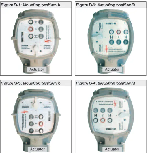
Mounting positions of the local controls
The mounting position of the local controls is designed according to the order. If, after mounting the actuator to the valve or the gearbox on site, the local controls is in an unfavorable position, the mounting position can easily be changed at a later date.
Four mounting positions are possible:
Changing the mounting position
.
Disconnect actuator from the mains before opening..
Turn local controls by a maximum of 180°, rotate circuit board accordingly!.
Ensure that the wires are neither twisted nor jammed..
Loosen 4 bolts and remove the local controls..
Turn local controls in one of the four positions and re-place on the actuator, rotate circuit board accordingly..
Clean sealing faces of housing and cover..
Check whether O-ring is in good condition..
Replace cover on switch compartment and fasten bolts evenly crosswise.Figure D-1: Mounting position A
Actuator
Figure D-2: Mounting position B
Actuator
Figure D-3: Mounting position C
Actuator
Figure D-4: Mounting position D
8.
Electrical connection
Work on the electrical system or equipment must only be carried out by a skilled electrician themselves or by specially instructed personnel under the control and supervision of such an electrician and in accordance with the applicable electrical engineering rules.
Wiring diagram
The terminal plan applicable to the actuator is placed inside the terminal com-partment, the operation instructions are attached to the handwheel in a weather-proof bag.
External fuse
For short-circuit protection and for protecting the actuator, fuses and disconnect switches have to be provided by the customer.
The current values for sizing the switch can be derived from the current con-sumption of the motor plus the current concon-sumption of the controls.
Motor current consumption:
Refer to name plate on motor (nominal current).
Current consumption of the controls depending on the mains voltage: 100 to 120 V AC = max. 650 mA
208 to 240 V AC = max. 325 mA 380 to 500 V AC = max. 190 mA
The maximum permissible fuse for controls with a rated power of 1.5 kW is 16 A (gL/ gG), and for controls with a rated power of 7.5 kW, the value amounts to 32 A (gL/ gG).
Cable installation in accordance with EMC
Signal and bus cables are susceptible to interference. Motor cables are interference sources.
.
Lay cables being susceptible to interference or sources of interference at the highest possible distance from each other..
The interference immunity of signal and bus cables increases if the cables are laid close to the ground potential..
If possible, avoid laying long cables and make sure that they are installed in areas being subject to low interference..
Avoid long parallel paths with cables being either susceptible to interference or interference sources..
For the connection of remote position transmitters (potentiometer, RWG), screened cables must be used.Heater
As standard, the control unit of the actuator is equipped with a heater to prevent condensation within the actuator. Unless ordered otherwise, the heater is inter-nally supplied. For external supply (option), the heater always has to be connected.
Some actuators are optionally equipped with an additional motor heater. The motor heater is always externally supplied and has to be connected according to the wiring diagram.
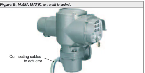
Actuator controls on wall bracket (accessory)
For version on wall bracket, please observe the following:
.
Versions with potentiometer in the actuator are not suitable. Instead of the potentiometer, an RWG has to be used in the actuator.
Permissible cable distance between actuator and AUMA MATIC amounts to a maximum of 100 m..
Factory supplied cables for the connection between actuator and AUMA MATIC on wall bracket can be obtained from AUMA on request.In case non factory supplied cables are used, the following additionally has to be observed:
.
Use suitable flexible and screened connecting cables..
Connect the wires in correct phase sequence.Check the direction of rotation before switching on (see page 26)
Subsequent mounting of the actuator controls on the actuator
In case the actuator and the actuator controls have different commission num-bers (refer to name plates), the designations of the terminal plan and the wiring diagram (KMS . . .) have to match for both devices.
Figure E: AUMA MATIC on wall bracket
Connecting cables to actuator
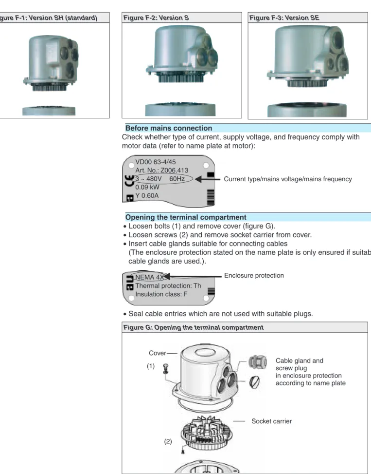
8.1 Connection with AUMA plug/ socket connector (S, SH, SE)
Before mains connection
Check whether type of current, supply voltage, and frequency comply with motor data (refer to name plate at motor):
Opening the terminal compartment
.
Loosen bolts (1) and remove cover (figure G)..
Loosen screws (2) and remove socket carrier from cover..
Insert cable glands suitable for connecting cables(The enclosure protection stated on the name plate is only ensured if suitable cable glands are used.).
.
Seal cable entries which are not used with suitable plugs.VD00 63-4/45 Art. No.: Z006.413 3 ~ 480V 60Hz 0.09 kW
Y 0.60A
Current type/mains voltage/mains frequency
NEMA 4X
Thermal protection: Th Insulation class: F
Enclosure protection
Figure F-1: Version SH (standard) Figure F-2: Version S Figure F-3: Version SE
Figure G: Opening the terminal compartment
Cover (1)
Socket carrier (2)
Cable gland and screw plug
in enclosure protection according to name plate
Connecting the cables
.
Connect cables according to order-related wiring diagram. Cross sections:- Power terminals (U1, V1, W1, U2, V2, W2) and protective earth (symbol: )
max. 6 mm² flexible, max. 10 mm² solid - Control contacts (1 to 50) = max. 2.5 mm²
.
All PE conductors have to be tightened firmly to the PE connection(symbol: ) using either ring lugs (flexible cables), or lugs (solid cables) (fig-ure H).
Each time the PE connection has been disconnected, it has to be ensured that the PE conductors are firmly connected.
Screw Washer Circlip
Protective earth with ring lugs/lugs PE connection
Socket carrier
Closing the terminal compartment
.
Insert socket carrier into the cover and fasten with screws (2) (figure G)..
Clean sealing faces at the cover and the housing..
Check whether O-ring is in good condition..
Apply a thin film of non-acidic grease (e.g. Vaseline) to the sealing faces..
Replace cover and fasten bolts (1) evenly crosswise..
Fasten cable glands with the specified torque to ensure the required enclo-sure protection.Parking frame, protection cover (accessories)
A special parking frame (figure J) for protection against touching the exposed contacts and against environmental influences is available.
The open terminal compartment can be closed using a protective cover (not illustrated).
Figure J: Parking frame (accessory)
Parking frame
9.
Manual operation
The actuator may be operated manually for purposes of setting and commis-sioning and in case of motor failure or power failure.
Manual operation is engaged by an internal change-over mechanism.
Engaging manual operation
.
Lift up change-over lever in the center of the handwheel to approx. 85°, while slightly turning the handwheel back and forth until manual operation engages (figure K-1).Manual force is sufficient for operating the change-over lever. It is not necessary to use an extension. Excessive force may damage the change-over mechanism.
.
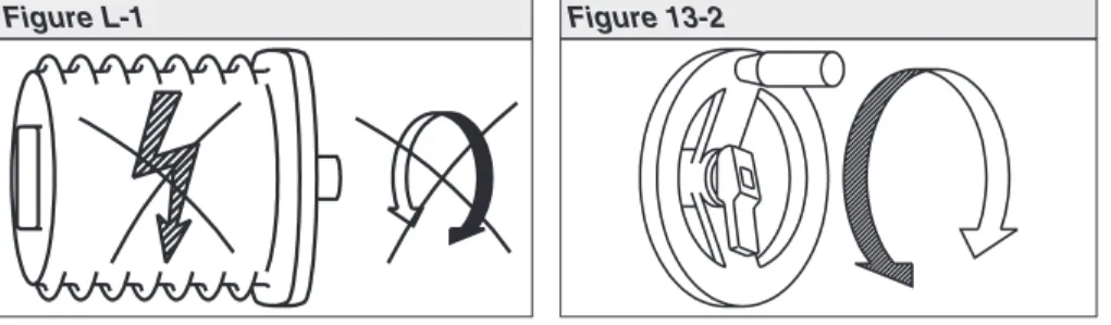
Release change-over lever (should snap back into initial position by spring action, figure K), if necessary, push it back manually.Operating the change-over lever while the motor is running (figure L-1) can lead to increased wear at the change-over mechanism.
.
Turn handwheel into desired direction (figure 13-2).Disengaging manual operation
Manual operation is automatically disengaged when motor is started again. The handwheel does not rotate during motor operation.
Figure K-1 Figure K-2
10.
Operation and indications of the local controls
Selector switch
Position OFF (0):
- No remote control possible - No local control possible
- Actuator remains ready for signalization
signalization (the controls’ power supply is maintained)
Position Local control (I):
The actuator can be operated locally via the push buttons OPEN - STOP - CLOSE.
Position Remote control (II):
The actuator can be controlled from remote, e.g. via the con-trol room.
Position Test (III):
Test PTC tripping device (refer to page 27)
Only available in combination with motor protection (PTC thermistor).
Yellow indication light (fault) is illuminated.
Position Reset (III):
Reset fault signal (yellow indication light) after the motor pro-tection has tripped (refer to page 54).
Only available in combination with motor protection (PTC thermistor).
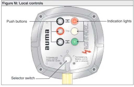
Figure M: Local controls
Selector switch
Push buttons Indication lights
I 0 I I 0 I I 0 I Reset III Test III I 0 II Test III Reset I II III 0
Push buttons
If the selector switch is in position local control (I), use the push buttons OPEN -STOP - CLOSE to operate the actuator locally.
OPEN: Actuator runs in direction OPEN
STOP: Actuator stops
CLOSE: Actuator runs in direction CLOSE
The operation commands OPEN - CLOSE can be used for control during push-to-run operation or in the self-retaining mode.
In the push-to-run operation, the actuator runs as long as the push button is pressed.
In the self-retaining mode, the actuator runs to the defined end position, unless another command has been received beforehand.
For further information on the programming, refer to page 35.
Indication lights
The 3 indication lights give the following signals (standard indication).
Illuminated (red): Actuator is in end position OPEN
Collective fault signal (yellow)
Illuminated (green): Actuator is in end position CLOSED
Collective fault signal:
The collective fault signal (yellow indication light) will be activated if one of the following events occurs:
.
Torque fault, i.e. the set torque (page 25) was exceeded before reaching an end position..
Motor protection has tripped (refer to page 54), i.e. the motor is overheated..
A phase failure (for 3-phase AC motors) has occurred..
Test PTC tripping deviceIndication lights are blinking:
If the actuator is equipped with a blinker, the indication lights can be used as running indication.
If the blinker transmitter is active (page 35), the respective indication light blinks during operation.
11.
Opening the switch compartment
To be able to carry out the following settings (up to and including clause 18.), the switch compartment must be opened and, if installed, the indicator disc must be removed.
These settings are only valid for “clockwise closing”, i.e. driven shaft turns clock-wise to close the valve.
Work on the electrical system or equipment must only be carried out by a skilled electrician themselves or by specially instructed personnel under the control and supervision of such an electrician and in accordance with the applicable electrical engineering rules.
11.1 Removing the cover from the switch compartment
.
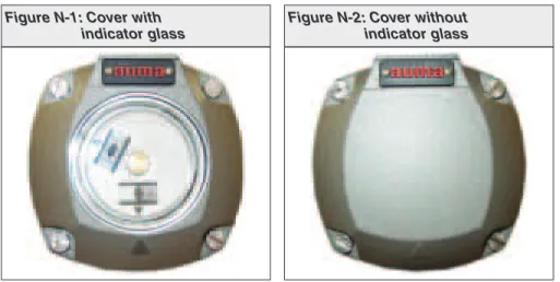
Loosen 4 bolts and take off the cover at the switch compartment (figure N-1 or figure N-2).11.2 Pulling off the indicator disc (option)
.
If installed, pull off indicator disc (figure O). Open end wrench may be used as lever.Figure N-1: Cover with indicator glass
Figure N-2: Cover without indicator glass
DS R
WD R
Figure O: Pulling off the indicator disc
12.
Setting the limit switching
12.1 Setting end position CLOSED (black section)
.
Turn handwheel clockwise until valve is closed..
Turn handwheel back by approximately half a turn (overrun). During test run check overrun and, if necessary, correct setting of the limit switching..
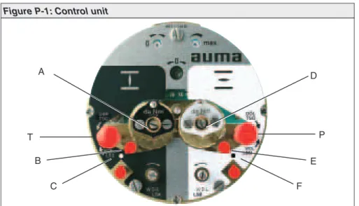
Press downand turn setting spindle A (figure P-1) with a flat blade screw driver in direction of arrow, thereby observe pointer B.While a ratchet is felt and heard, the pointer B moves 90° every time.
When pointer B is 90° from mark C, continue turning slowly. When pointer B has reached the mark C, stop turning and release setting spindle. If you override the trip-ping point inadvertently (ratchet is heard after the pointer has rotated), continue turn-ing the settturn-ing spindle in the same direction and repeat settturn-ing process.
12.2 Setting end position OPEN (white section)
.
Turn handwheel counterclockwise until valve is open..
Turn handwheel back by approximately ½ a turn (overrun). During test run check overrun and, if necessary, correct setting of the limit switching..
Press downand turn setting spindle D (figure P-1) with a flat blade screw driver in direction of arrow, thereby observe pointer E.While a ratchet is felt and heard, the pointer E moves 90° every time. When pointer E is 90° from mark F, continue turning slowly.
When pointer E has reached the mark F, stop turning and release setting spindle. If you override the tripping point inadvertently (ratchet is heard after the pointer has rotated), continue turning the setting spindle in the same direction and repeat setting process.
12.3 Checking the limit switches
The red test buttons T and P (figure P-1) are used for manual operation of the limit switches.
.
Turning T in direction of the arrow LSC (WSR) triggers limit switch CLOSED.The green indication light on the local controls is illuminated as long as the test button is pushed down.
.
Figure P-1: Control unit
A T B C D P E F
13.
Setting the DUO limit switching (option)
Any application can be switched on or off via the two intermediate position switches.
For setting, the switching point (intermediate position) must be approached from the same direction as later during
electrical operation. 13.1 Setting direction CLOSE (black section)
.
Move valve to desired intermediate position..
Press downand turn setting spindle G (figure P-2) with a flat blade screw driver in direction of arrow, while observing pointer H.While a ratchet is felt and heard, the pointer H moves 90° every time.
When pointer H is 90° from mark C, continue turning slowly. When pointer H has reached the mark C, stop turning and release setting spindle. If you override the trip-ping point inadvertently (ratchet is heard after the pointer has rotated), continue turn-ing the settturn-ing spindle in the same direction and repeat settturn-ing process.
13.2 Setting direction OPEN (white section)
.
Move valve to desired intermediate position..
Press downand turn setting spindle K (figure P-2) with a flat blade screw driver in direction of arrow, while observing pointer L.While a ratchet is felt and heard, the pointer L moves 90° every time.
When pointer L is 90° from mark F, continue turning slowly. When pointer L has reached the mark F, stop turning and release setting spindle. If you override the trip-ping point inadvertently (ratchet is heard after the pointer has rotated), continue turn-ing the settturn-ing spindle in the same direction and repeat settturn-ing process.
13.3 Checking the DUO limit switches
The red test buttons T and P (figure P-2) are used for manual operation of the DUO limit switches.
.
Turning T in direction of the arrow TSC (DSR) triggers DUO limit switch CLOSED. The torque switch CLOSED is actuated at the same time..
Turning P in direction of the arrow TSO (DÖL) triggers DUO limit switch OPEN. The torque switch OPEN is actuated at the same time..
After checking the switches, the fault (red indication light) has to be reset using the OPEN or CLOSE push buttons of the local controls for operation in the opposite direc-tion.Figure P-2: Control unit
G T H C K P L F
14.
Setting the torque switching
14.1 Setting
.
The set torque must suit the valve!.
This setting must only be changed with the consent of the valve manufacturer!.
Loosen both lock screws O at the torque dial (figure Q)..
Turn torque dial P to set it to the required torque. Example:Figure Q shows the following setting: 35 ft lbs for direction CLOSE 25 ft lbs for direction OPEN
.
Tighten lock screws O again.
The torque switches can also be operated in manual operation..
The torque switching acts as overload protection over full travel, also when stopping in the end positions by limit switch-ing.14.2 Checking the torque switches
The red test buttons T and P (figure P-1) are used for manual operation of the torque switches:
.
Turning T in direction of the arrow TSC (DSR) triggers torque switch CLOSED.The yellow indication light (fault) on the local controls is illuminated.
.
Turning P in direction of the arrow TSO (DÖL) triggers torque switch OPEN. The yellow indication light (fault) on the local controls is illuminated..
If a DUO limit switching (optional) is installed in the actuator, the intermediate position switches will be operated at the same time..
After checking the switches, the fault (yellow indication light) has to be reset using the OPEN or CLOSE push buttons of the local controls for operation in the opposite direction.Ft. Lbs Ft. Lbs 15 35 45 25 45 25 15 35
Figure Q: Torque switching heads
Setting CLOSED Setting OPEN
O P
15.
Test run
15.1 Checking the direction of rotation
.
If provided, place indicator disc on shaft.The direction of rotation of the indicator disc (figure R-1) indicates the direc-tion of rotadirec-tion of the output drive.
.
If there is no indicator disc, the direction of rotation can also be observed on the hollow shaft. For this purpose, remove screw plug (no. 27)(figure R-2).
.
Move actuator manually to intermediate position or to sufficient distance from end position..
Set selector switch to local control (I) (figure S)..
Switch on the voltage supply..
Press push button CLOSE (figure T-1) and observe the direction of rotation:If the indicator disc turns counterclockwise, the direction of rotation is correct.
If the direction of rotation is wrong, switch off immediately.
Afterwards, correct phase sequence in the connecting cable from the wall bracket to the actuator and repeat test run.
Figure R-1: Indicator disc
CLOSED OPEN
Figure R-2: Opening the hollow shaft
27 S1/S2
Figure S: Selector switch LOCAL
15.2 Checking the setting of the limit switching
.
Set selector switch to position OFF (0) (figure U-1).The controls’ power supply is maintained in position OFF.
.
Move actuator manually into both end positions of the valve..
Check if limit switching is set correctly for both end positions. Hereby observe that the appropriate switch is tripped in each end position and released again after the direction of rotation is changed. If this is not the case, the limit switching must be set again.When limit switching is set correctly:
.
Set selector switch to local control (I) (figure S)..
Perform test run at the local controls via push buttons OPEN STOP -CLOSE.15.3 Checking the type of seating
The valve manufacturer states whether switching off in the end positions should be by limit switch (limit seating) or torque switch (torque seating).
.
For checking the setting, refer to page 35, subclause 20.2.15.4 Checking the PTC tripping device (option)
.
Turn selector switch to position TEST (wiping) (figure U-2).
If the PTC tripping device is working properly, the tripping of the motor protec-tion is signaled via the collective fault signal (refer to wiring diagram) and via the fault indication light on the local controls.
.
Turn selector switch to position RESET (wiping) (figure U-3): The fault signal is reset if the device is working properly.Figure U-1: Selector switch OFF
Figure U-2: Selector switch TEST
In case the selector switch position TEST does not initiate a fault signal, the wir-ing and the selector switch have to be checked by the AUMA service.
If no other options (clauses 16. to 18.) require setting:
.
Close switch compartment (see page 33, clause 19.).16.
Setting the potentiometer (option)
— For remote indication —
.
Move valve toend position CLOSED..
Turn potentiometer (E2) clockwise to the stop.End position CLOSED corresponds to 0 %, end position OPEN to 100 %.
.
Turn potentiometer (E2) slightly back.Due to the ratio of the reduction gearings for the position trans-mitter, the complete resistance range is not always utilized for the whole travel. Therefore, an external possibility for adjust-ment (setting potentiometer) must be provided.
.
Perform fine-tuning of the zero point at external setting potentiometer (for remote indication).Figure V: Control unit
17.
Setting the electronic position transmitter RWG (option)
— For remote indication or external control —
After mounting the actuator on the valve, check setting and adjust, if necessary (refer to subclauses 17.1 or 17.2).
The position transmitter board (figure W) is located under the cover plate (figure Y). Terminal plans KMS TP_ _ 4 / _ _ _ 3- or 4- wire system KMS TP _ 4 _ / _ _ _ KMS TP _ 5 _ / _ _ _ 2-wire system Output current Ia 0 – 20 mA, 4 – 20 mA 4 – 20 mA Power supply Uv 24 V DC, ±15 % smoothed 14 V DC + (I x RB), max. 30 V Max. input current I 24 mA at 20 mA output current 20 mA Max. load RB 600Ω (Uv - 14 V) / 20 mA
Table 3: Technical data RWG 4020
Figure W: Position transmitter board
17.1 Setting 2-wire system 4 – 20 mA and 3- /4-wire system 0 – 20 mA
.
Connect voltage to electronic position transmitter via AM..
Move valve toend position CLOSED..
Connect ammeter for 0 – 20 mA to measuring points (figure Y-1).The circuit (external load) must be connected
(observe max. load RB), or the appropriate poles at the terminals
(refer to wiring diagram) must be linked, otherwise no value can be measured.
.
Turn potentiometer (E2) clockwise to the stop..
Turn potentiometer (E2) back a little..
Turn potentiometer “0” clockwise until output current starts to increase..
Turn potentiometer “0” back until the following value is reached: for 3- or 4-wire system: approx. 0.1 mAfor 2-wire system: approx. 4.1 mA.
This ensures that the signal remains above the dead and live zero point.
.
Move valve to end position OPEN..
Set potentiometer “max.” to end value 20 mA..
Approach end position CLOSED again and check minimum value (0.1 mA or 4.1 mA). If necessary, correct the setting.If the maximum value cannot be reached, the selection of the reduction gearing must be checked.
Figure Y-1
“0” (0/4 mA) “max.” (20 mA) Meas.point (+)
0/4 – 20 mA
Meas.point (–) 0/4 – 20 mA
17.2 Setting 3- / 4- wire system 4 – 20 mA
.
Connect voltage to electronic position transmitter via AM..
Move valve toend position CLOSED..
Connect ammeter for 0 – 20 mA to measuring points (figure Y-2).The circuit (external load) must be connected
(observe max. load RB), or the appropriate poles at the terminals
(refer to wiring diagram) must be linked, otherwise no value can be measured.
.
Turn potentiometer (E2) clockwise to the stop..
Turn potentiometer (E2) back a little..
Turn potentiometer “0” clockwise until output current starts to increase..
Turn back potentiometer “0” until a residual current of approx. 0.1 mA is reached..
Move valve to end position OPEN..
Set potentiometer “max.” to end value 16 mA..
Move valve to end position CLOSED..
Set potentiometer “0” from 0.1 mA to initial value 4 mA.This results in a simultaneous shift of the end value by 4 mA, so that the range is now 4 – 20 mA.
.
Approach both end positions again and check setting. If necessary, correct the setting.If the maximum value cannot be reached, the selection of the reduction gearing must be checked.
Figure Y-2
“0” (0/4 mA) “max.” (20 mA) Meas. point (+)
0/4 – 20 mA
Meas. point (–) 0/4 – 20 mA
.
Place indicator disc on shaft..
Move valve toend position CLOSED..
Turn lower indicator disc (figure Z-1) until symbol CLOSED is in alignment with the mark on the cover (figure Z-2)..
Move actuator to end position OPEN..
Hold lower indicator disc CLOSED in position and turn upper disc with sym-bol OPEN until it is in alignment with the mark on the cover.Indicator disc rotates approximately 180° to 230° at full travel from OPEN to CLOSED or vice versa. For this purpose, a suitable reduction gearing was installed in our factory.
If the turns per stroke of the actuator are changed at a later date, the reduction gearing may have to be exchanged.
19.
Closing the switch compartment
.
Clean sealing faces of housing and cover.
Check whether O-ring is in good condition..
Apply a thin film of non-acidic grease to the sealing faces..
Replace cover on switch compartment and fasten bolts evenly crosswise.Check the multi-turn actuator for damage to paint finish. If damage to paint-finish has occurred after mounting, it has to be touched up to avoid corrosion.
Figure Z-1
Indicator disc
Figure Z-2
20.
Actuator controls AUMA MATIC
20.1 Functions of the diagnosis LEDs on the interface board (standard version)
V14 is illuminated: Phase failure and/ or motor protection tripped. In combination with motor protection (PTC thermistor) (option):
Reset by selector switch positionIIIat local controls V15 is illuminated: Torque fault: Torque switch operated in mid-travel
The LEDs STOP, CLOSE, OPEN indicate the available control commands (only in selector switch position REMOTE).
Figure AA: Positions of the boards within the controls
Timer board (option) Cover plate Interface board Logic boards Cover Positioner board (option)
20.2 Programming the logic board
The type of seating – limit or torque seating – (switch S1-2 and switch S3-2, fig-ure AC) must be determined by the valve manufactfig-urer.
.
Set desired programming according to table 4 at the switch S2-2.Position 1:
Limit seating
in end position OPEN Position 2:
Torque seating
in end position OPEN Position 1:
Limit seating
in end position CLOSED Position 2:
Torque seating
in end position CLOSED S3-2
S1-2 S2-2
Figure AC: Logic board A2
DIP switch S2-2 Programming
(ON = pressed)
Direction CLOSE Direction OPEN Self-retaining REMOTE
Push-to-run operation REMOTE Self-retaining LOCAL
Push-to-run operation LOCAL Blinker transmitter (option)
activated deactivated Torque fault: Torque switch
trip-ping (in mid-travel) contained in collective fault signal
included not included
20.3 EMERGENCY - OPEN and EMERGENCY - CLOSE signal (option)
(5thdigit in wiring diagram MSP … C, D, or P)
When an EMERGENCY run command is given, the actuator operates the valve to the predetermined end position (effective in all three selector switch positions: LOCAL, OFF, REMOTE).
.
The input at terminal XK1 (refer to wiring diagram) must be connected to anNC contact (closed circuit principle).
.
If EMERGENCY - OPEN or EMERGENCY - CLOSE signal is generally not desired:Take off cover plate and disconnect links B1 (for EMERGENCY - CLOSE) and B2 (for EMERGENCY - OPEN).
Figure AD: Cover plate for EMERGENCY - OPEN or EMERGENCY - CLOSE option
Links:B1 (EMERGENCY-CLOSE) B2 (EMERGENCY-OPEN)
LED for
EMERGENCY run command
B2 B1
21.
Electronic positioner (option)
21.1 Technical data
21.2 Setting
The positioner in the actuator controls AUMA MATIC is programmed
according to the purchase order details and is set together with the actuator prior to delivery.
Due to peculiarities of the regulating system not known beforehand, a readjustment may become necessary. Before adjusting the positioner, the programming of the positioner should be checked.
.
Check programming of the logic board according to subclause 20.2.The self-retaining REMOTE function (see table 4) must be switched off in conjunction with the positioner.
.
Take off cover plate (figure AE) and carry out required programming at positioner board (figure AF) according to tables 6 and 7.Command signal (input signal E1, set value) 0/4 – 20 mA (option: 0 – 5 V) Feedback (input signal E2, actual value) 0 – 5 V (option: 0/4 – 20 mA) Sensitivity (dead band) ΔE (P9) 0.5 % – 2.5 %
Fine tuning “Sens” (P7)
(useful for output speeds < 16 rpm only; not possible with 1-phase AC motors)
min. 0.25 % Pause time “t-off ”(P10) 0.5 – 10 s Input resistance 250 Ohm
Modulating duty with stepping mode(not required for modulating setting):
Running time “t-on” (P8)
effective until error is≤25 %; then set value is automatically reduced by 3.
0.5 – 15 s
Prior to setting, it must be ensured that the circuit for the position feedback E2 (see wiring diagram) is closed (measuring device or link). In case of missing signal E2, the LED (V10) “E1/E2 < 4 mA” (figure AE) is illuminated and the positioner shows no reaction.
21.2.1 Setting type of signal
The signal type (current/ voltage signal) of nominal value E1 and actual value E2 is set in the factory and marked with a label on the cover plate of the positioner (refer to figure AE).
For split range version (page 38) and for versions with a setpoint
E1≠0/4 – 20 mA, it is possible to change the type of signalling. For these ver-sions, the positioner board is equipped with an additional switch S1-7.
Figure AE: Cover plate positioner
V10 (red) P10 P8 Label with signal indication
(in our example: E1 = 4 – 20 mA, E2 = 4 – 20 mA)
Figure AF: Positioner board A7
V28 V27 V18 V10 P10 MP2(+) MP1(–) S1-7 P9 (ΔE) P7 (Sens) P3 (0) P4 (max) S2-7 S3-7 E2
{
Meas. points:If the setting is subject to subsequent change, the marking also has to be changed. Furthermore, the wiring diagram indicated on the name plate of the actuator controls also changes (see page 61).
Programming
Command signal Setpoint E1
Feedback Actual value E21)
via DIP switch S1-7 (see figure AF) 4 – 20 mA 0 – 20 mA 4 – 20 mA 0 – 20 mA 4 – 20 mA 0 – 20 mA 0 – 5 V 0 – 5 V 4 – 20 mA 0 – 20 mA 0 – 5 V 0 – 5 V 0 – 10 V 4 – 20 mA 0 – 20 mA 0 – 10 V 0 – 5 V 1) Signals for internal feedback:
0/4 – 20 mA from electronic position transmitter or 0 – 5 V from precision potentiometer 5 kΩ
21.2.2 Setting actuator behavior on loss of signal
In case of a loss of signal of nominal value E1 or actual value E2, the reaction of the actuator can be programmed via the switch S2-7. The complete range of choices, however, is only available with signals 4 – 20 mA.
The following reactions are possible:
Fail as is:
Actuator stops immediately and remains in this position.
Fail close
Actuator moves the valve to the end position CLOSED.
Fail open:
Actuator moves the valve to the end position OPEN.
Behavior on loss of signal of Prerequisite1) Programming
E1 E2 Command signal Setpoint E1
Feedback Actual value E22)
via DIP switch S2-7 (see figure AF) fail as is 4 – 20 mA 4 – 20 mA fail close 4 – 20 mA 4 – 20 mA 0 – 20 mA 0 – 5 V 4 – 20 mA fail open 4 – 20 mA 4 – 20 mA 4 – 20 mA 0 – 20 mA 0 – 5 V fail as is fail open 4 – 20 mA 0 – 5 V
fail close fail open
4 – 20 mA 0 – 20 mA 0 – 5 V 0 – 20 mA 4 – 20 mA 0 – 20 mA 0 – 5 V 0 – 10 V 0 – 20 mA 0 – 5 V fail close fail as is
0 – 20 mA 4 – 20 mA 0 – 10 V 4 – 20 mA
1) During loss of signal, signals from 0 – 20 mA and 0 – 5 V may be misinterpreted since E1 or E2 (without any fault) can also be < 4 mA (end position CLOSED = 0 mA or 0 V) when working properly.
2) Signals for internal feedback:
0/4 – 20 mA from electronic position transmitter or 0 – 5 V from precision potentiometer 5 kΩ
21.3 Positioner adjustment for end position CLOSED (standard version)
Before beginning the setting of the positioner, it has to be ensured that the limit and torque switching of the actuator as well as the feedback have been set (clauses 16. and 17.).
.
Set selector switch (local controls) to position LOCAL..
Move multi-turn actuator by pressing push button toend position CLOSED.
.
Supply nominal value E1 of 0 or 4 mA (see wiring diagram)..
Turn potentiometer “t-off” (P10) counterclockwise to the stop (figure AG).Missing signals E1/ E2 or wrong polarity are indicated by LED (V10) “E1/E2 < 4 mA" (figures AE or AG)
.
Connect voltmeter to measuring points MP3 and MP4 (figure AG) for measur-ing the nominal value (0 – 5 V).For a nominal value E1 of 0 mA, the voltmeter shows 0 V. For a nominal value E1 of 4 mA, the voltmeter shows 1 V. In case nominal value (0 V or 1 V) is not correct:
Correct nominal value signal from control room.
.
Connect voltmeter to measuring points MP2 and MP1 for measuring the actual value signal.For an actual value E2 of 0 V, the voltmeter shows 0 V. For an actual value E2 of 5 V, the voltmeter shows 1 V. If measured value is not correct:
Adjust position feedback according to clause 16. and 17. and repeat “positioner adjustment”.
If
Possible LED display:
(refer to figures AG and AH)
Then
Required setting in end position CLOSED:
(refer to figures AG and AH)
the LEDs are not illuminated Turn potentiometer “0” (P3) slowly clockwise until LED (V27 yellow) is illuminated
LED (V28 green) is illuminated
Turn potentiometer “0” (P3) slowly clockwise until LED (V28 green) is no longer illuminated and LED (V27 yellow) is illuminated
LED (V27 yellow) is illuminated
Turn potentiometer “0” (P3) counterclockwise until LED (V27 yellow) is no longer illuminated. Then turn potentiometer “0” (P3) slightly clockwise until LED (V27 yellow) is illuminated
Measuring points: MP3(+)/MP4(–) for E1
Figure AG: Positioner board A7
V28 V27 V18 V10 P10 MP4(–) MP3(+) MP2(+) MP1(–) S1-7 P9 (ΔE) P7 (Sens) P3 (0) P4 (max) S2-7 S3-7 E2
{
Meas. points:21.4 Positioner adjustment for end position OPEN (standard version)
.
Run multi-turn actuator by pressing push button (local controls) toend posi-tion OPEN..
Connect voltmeter to measuring points MP2 and MP1 for measuring the actual value E2:When position feedback is set correctly, the voltmeter shows approx. 5 V. If measured value is not correct:
Adjust position feedback according to clause 16. and 17. and repeat “positioner adjustment”.
.
Connect max. command signal (nominal value E1) = 20 mA..
Connect voltmeter to measuring points MP4 and MP3 for measuring the nom-inal value E1:For a nominal value of 20 mA, the voltmeter shows 5 V. If measured value is not 5 V:
Check the externally supplied command signal E1.
21.5 Setting the sensitivity
.
Set selector switch at the local controls to position REMOTE.
.
Set command signal E1 according to label on cover plate (see figure AH). The sensitivity (ΔE / dead band) is set to maximum value (2.5 %) in the fac-tory..
The deadband can be increased by turning the potentiometerΔE (P9) clock-wise. Left stop = small dead band (= high sensitivity). For a precise setting of the dead band, a set point device with setting options in the 0.1 mA range is required..
A better sensitivity (ΔEmin= 0.25 %) can be achieved by turning thepotentiom-eter P7 (sens) clockwise.
When setting E, the following must be observed:
If the number of starts is too high, this will lead to unnecessary wear at the valve and actuator. Therefore the maximum possible dead band acceptable for the process must be set.
To prevent exceeding the max. permissible number of starts (refer to Technical data sheets for modulating actuators) in extreme cases, a pause time between 0.5 s (left stop) and 10s (right stop) may be set with the
potentio-meter “t-off” (P10).
If
LED display:
(refer to figures AG and AH)
Then
Required setting in end position OPEN:
(refer to figures AG and AH)
the LEDs are not illuminated Turn potentiometer “max.” (P4) slowly counterclockwise until LED (V28 green) is illuminated
LED (V28 green) is illuminated
Turn potentiometer “max” (P4) clockwise until LED (V28 green) is no longer illuminated.
Then turn potentiometer “max” (P4) slowly counterclockwise until LED (V28 green) is illuminated
LED (V27 yellow) is illuminated
Turn potentiometer “max” (P4) slowly counterclockwise until LED (V27 yellow) is no longer illuminated and
LED (V28 green) is illuminated
Figure AH: Cover plate for positioner
Label with signal indication
(in our example: E1 = 4 – 20 mA, E2 = 4 – 20 mA)
V28 (green) V27 (yellow) V18 (red) V10 (red) P10
Figure AI: Cover plate for positioner A7
V28 V27 V18 V10 P10 MP2(+) MP1(–) S1-7 P9 (ΔE) P7 (Sens) P3 (0) P4 (max) S2-7 S3-7 E2
{
Meas. points:21.6 Positioner adjustment for end position OPEN (inverse operation)
In standard version the maximum input signal (E1 = 20 mA) results in operation to end position OPEN.
.
By switching the code switch S3-7 (figure AJ) to position “1”, an inversion of this signal definition (inverse operation) can be achieved..
In case an RWG (option) is installed, the connections 7 (red) and 5 (black) on the positioner board (figure W) of the actuator have to be exchanged..
In case a potentiometer is installed, (option) the connections 21 (red) and 22 (black) at XA (connection for actuator) must be interchanged.Before beginning the setting of the positioner, it has to be ensured that the limit and torque switching of the actuator as well as the feedback have been set (clauses 16. and 17.).
.
Set selector switch (local controls) to position LOCAL..
Run actuator with push button toend position OPEN..
Supply nominal value E1 of 0 or 4 mA (see wiring diagram)..
Turn potentiometer “t-off” (P10) counterclockwise to the stop (figure AJ).Missing signals E1/ E2 or wrong polarity are indicated by LED (V10) “E1/E2 < 4 mA" (figures AH or AJ)
.
Connect voltmeter to measuring points MP3 and MP4 (figure AJ) for measur-ing the nominal value (0 – 5 V).For a nominal value E1 of 0 mA, the voltmeter shows 0 V. For a nominal value E1 of 4 mA, the voltmeter shows 1 V. In case nominal value (0 V or 1 V) is not correct:
Correct nominal value signal in control room.
.
Connect voltmeter to measuring points MP2 and MP1 for measuring the actual value signal.For an actual value E2 of 0 V, the voltmeter shows 0 V. For an actual value E2 of 5 V, the voltmeter shows 1 V.
Adjust position feedback according to clause 16. and 17. and repeat “positioner adjustment”.
If
Possible LED display:
(refer to figures AH and AJ)
Then
Required setting in end position OPEN:
(refer to figures AH and AJ)
the LEDs are not illuminated Turn potentiometer “0” (P3) slowly clockwise until LED (V28 green) is illuminated
LED (V27 yellow) is illuminated
Turn potentiometer “0” (P3) slowly clockwise until LED (V27 yellow) is no longer illuminated and LED (V28 green) is illuminated
LED (V28 green) is illuminated
Turn potentiometer “0” (P3) counterclockwise until LED (V28 green) is no longer illuminated. Then turn potentiometer “0” (P3) slowly clockwise until LED (V27 yellow) is illuminated