CONTRACT NAS9-9953 MSC 02471 DRL NO: MSC-T-575, LINE IT"~M 72
SD 72-SA-114-1
SD 72-SA-01 14-1
MODULAR
space station
PHASE B EXTENSION
INFORMATION MANAGEMENT ADVANCED
DEVELOPMENT FINAL REPORT
Volume I: Summary
PREPARED BY PROGRAM ENGINEERING JULY 31, 1972
(NASA-CR-128554) INFORMATION MANAGEMENT
ADVANCED DEVELOPMENT. VOLUME 1: SUMMARY
Information Management Advanced Development C.R. Gerber, et al (North American Rockwell
Corp.) 31 Jul. 1972 110 p CSCL 22B G3/31
Reproduced by
NATIONAL TECHNICAL INFORMATION SERVICE
U S Deportment of Commerce
Springfield VA 22151
I
Space DivisionNorth American Rockwell
1 2 2 1 4 Lakewood Boulevard, Downey. C a I , f o r n i a 90241
/W I
-9a8
DRL NO: MSC-T-575, LINE ITEM 72
SD 72-SA-0114-1
MODULAR
space
station
PHASE B EXTENSION
INFORMATION MANAGEMENT ADVANCED DEVELOPMENT FINAL REPORT
Volume I: Summary
31 JULY 1972
PREPARED BY PROGRAM ENGINEERING
Approved by
Ih
-~)
iL/(
/ James Madewell
Director
Space Applications Programs
TECHNICAL REPORT INDEX/ABSTRACT
... I .I IIr
I I I
I DOCUMENT SECURITY CLASSIFICATIONITCCE LOF NUDBERNT
TITLE OF DOCUMENT LIBRARY USE ONLY
INFORMATION MANAGEMENT ADVANCED DEVELOPMENT FINAL REPORT, Volume I, Summary
AU THOR[S)
Gerber, C. R.,et.al.
CODE
ORIGINATING AGENCY AND OTHER SOURCES DOCUMENT NUMBER
QN085282 Space Division of North American SD 72-SA-0114-1
Rockwell Corporation, Downey, California PUBLI CATION DATE CONTRACT NUMBER
July 31. 1972 NAS9-9953
FORM M 131-V REV. 1-68
DESCRIPTIVE TERMS
*MODULAR SPACE STATION, *INFORMATION MANAGEMENT,
*ADVANCED DEVELOPMENT, *COMMUNICATIONS, *DATA PROCESSING, *SOFTWARE, *DATA BUS, *DATA STORAGE, *BREADBOARDS,
*TECHNOLOGY, *SPECIFICATIONS
ABSTRACT
THIS DOCUMENT IS VOLUME I OF THE FINAL REPORT OF THE MODULAR SPACE
STATION ADVANCED DEVELOPMENT STUDY. IT SUMMARIZES THE RESULTS OF
AN 18-MONTH STUDY, HARDWARE DESIGN AND TEST PROGRAM WHICH
INVESTIGATED AREAS OF INFORMATION MANAGEMENT TECHNOLOGY REQUIRING ADVANCED DEVELOPMENT.. THE TASKS INCLUDED THE CONSTRUCTION OF BREADBOARD MODELS OF THE 10 MEGABIT PER SECOND DATA BUS AND THE
K-BAND COMMUNICATIONS TERMINAL ANTENNA-MOUNTED ELECTRONICS. THE
REMAINING TASKS WERE STUDIES TO FURTHER DEFINE THE DATA PROCESSING AND SOFTWARE ASSEMBLIES RESULTING IN PERFORMANCE SPECIFICATIONS AND DEVELOPMENT PLANS/SCHEDULES FOR ADDITIONAL BREADBOARD OR PROTOTYPE EQUIPMENTS.
I'
I
0
A
North American Rockwell
FOREWORD
This document is one of a series required by Contract NAS9-9953, Exhibit C, Statement of Work, for the Phase B Extension - Modular Space
Station Program Definition. It has been prepared by the Space Division, North American Rockwell Corporation, and is submitted to the National
Aero-nautics and Space Administration's Manned Spacecraft Center, Houston,
Texas, in accordance with the requirements of the Data Requirements List, (DRL) MSC-T-575, Line Item 72.
This document is Volume I of the Modular Space Station Information
Management System Advanced Development Technology Report, which has been prepared in the following five volumes:
I IMS ADT Summary
II IMS ADT Communications Terminal
Breadboard
III IMS ADT Digital Data Bus Breadboard
IV IMS ADT Data Processing Assembly
V IMS ADT Software Assembly
SD72- SA- 0114- 1
SD72- SA- O114- 2
SD72- SA- 0114- 3
SD72- SA- 0114- 4
PRECEDING PAGE BLANK NOT FILMED
Space Division
9ft
North American Rockwell
ACKNOWLEDGEMENTS
The following persons have participated in the conduct of the IMS ADT tasks, and have contributed to this report:
C. W. Roberts Experiment/Electronics Manager
C. R. Gerber Information Systems Project Engineer
B. A. Logan, Jr. Information Systems
E. Mehrbach Information Systems
D. W. Brewer Information Systems
V. R. Hodgson Information Systems
The-following subcontractors have supported the IMS ADT tasks in specialized areas:
International Tel. & Tel. Nutley, New Jersey
B. Cooper, Proj. Mgr. Communications Data Bus BB Terminal B.B. Intermetrics Cambridge, Mass. J. Miller, Prog. Mgr. System Develop. Corp. Santa Monica, Calif.
R. Bilek, Prog. Mgr. Gen'l Electric Corp. Valley Forge, Pa.
R. Kirby, Prog. Mgr. NR-Autonetics
Anaheim, Calif.
J. Jurison, Proj. Mgr.
Data Processing Assy
Data Processing Assy Software Assy
Bulk Storage Technology
Data Bus BB
Data Processing Assy
Preceding page blank I
PRECEDING PAGE BLANK NOT FILMED
0 North American RockwellCONTENTS
INTRODUCTION 1.1 OVERVIEW
COMMUNICATIONS TERMINAL BREADBOARD.
2.1 SUMMARY .
2.2 CTB GENERAL DESCRIPTION. 2.3 TECHNOLOGY GOALS
2.4 HISTORY .
DIGITAL DATA BUS BREADBOARD 3.1 DACS REOUIREMENTS SUMMARY 3.2 DACS BREADBOARD DESIGN DATA
4.1 4.2 4.3
PROCESSING ASSEMBLY DEFINITION
SUMMARY . .
DPA DEFINITION .
DPA ENGINEERING MODEL DEVELOPMENT PLAN COMPUTER PROGRAM (SOFTWARE) ASSEMBLY DEFINITION
5.1 SUMMARY . . . .
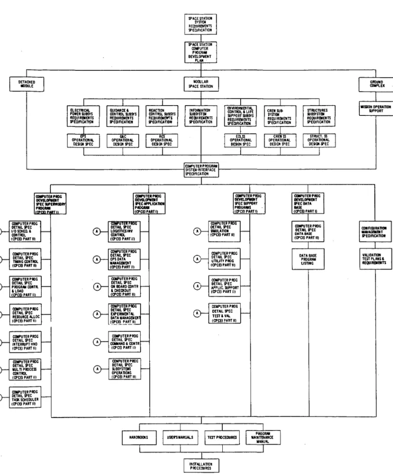
5.2 MSS SOFTWARE STANDARDS AND CONVENTIONS 5.3 COMPUTER PROGRAM SPECIFICATION TREE. 5.4 COMPUTER PROGRAM DEVELOPMENT PLAN
5.5 COMPUTER-ASSISTED RESOURCE ALLOCATION AND
UTILIZATION . . .
DPA SUPERVISOR PROGRAM. . .
6.1 MSS OPERATIONS CONTROL CENTER PROCESSOR SUPERVISOR COMPUTER PROGRAM SPECIFICATION
(PRELIMINARY) . .
RECOMMENDATIONS FOR UTILIZATION OF ADT
ACCOMPLISHMENTS . . .
Preceding page blank
Page 1-1 1-3 2-1 2-1 2-2 2-3 2-10 Section 1.0 2.0 3.0 4.0 5.0 6.0 7.0 3-1 3-1 3-5 4-1 4-1 4-8 4-19 5-1 5-1 5-2 5-3 5-13 5-13 6-1 6-1 7-1
9u
North Amencan Rockwell
PRECEDING PAGE BLANK NOT FILMED
ILLUSTRATIONS
Figure Page
1-1 MSS Functional Allocations . . . 1-2
1-2 MSS Information Subsystem . . . 1-4
1-3 Advanced Development Technology Plan . . . . 1-5
1-4 Modular Space Station/Advanced Development
Interactions . 1-6
1-5 Subcontractor Organization . . 1-8
1-6 Advanced Development Work Package/TDL System . . 1-9
2-1 External Communication Link Requirements . 2-4
2-2 Communications Terminal Breadboard Block Diagram . . 2-6
2-3 CTB Hardware Identification . . . 2-7
2-4 Communications Terminal Breadboard System (CTB) . 2-8
2-5 CTB Antenna Mounted Electronics Subassembly Package
-Oblique View, Mounting-and Interconnect Face 2-9
3-1 DACS Work Breakdown and Flow . 3-2
3-2 Recommended DACS Configuration . 3-4
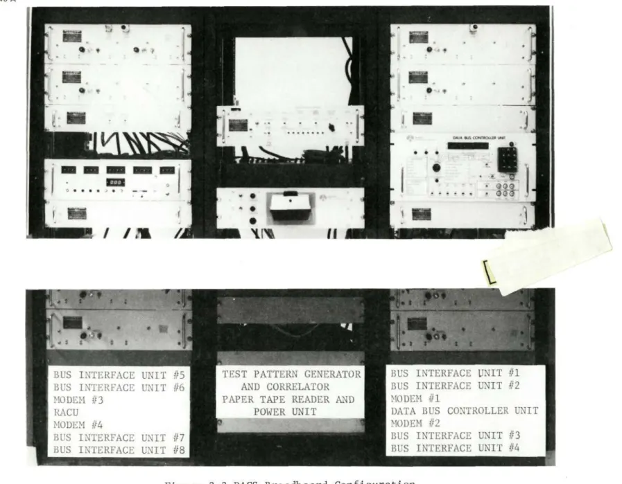
3-3 DACS Breadboard Configuration . . 3-10
4-1 Data Processing Assembly (DPA) . . 4-2
4-2 DPA General Diagram. . . . 4-3
4-3 Data Processing Assembly Distribution . 4-4
4-4 Data Processing Assembly Configuration Study . 4-6
4-5 Processor Utilization . 4-9
4-6 Basic Recommended Redundancy Configuration . . 4-10
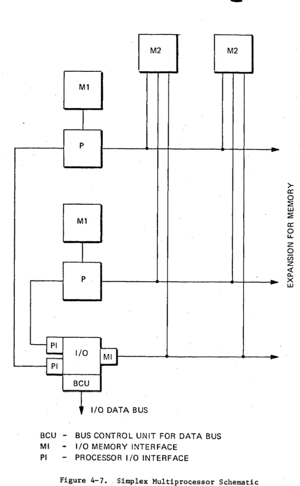
4-7 Simplex Multiprocessor Schematic . . 4-12
4-8 Memory Hierarchy . . . . 4-13
4-9 Internal Bus Configuration . . 4-14
4-10 Detailed CP Subsystem Functional Allocations . 4-18
4-11 ADT Breadboards Related to ADT Plan . 4-23
4-12 Relationship of EEM Processor Development to ADT
Extension . 4-25
4-13 Procurement Options for a Dual Multiprocessor 4-29
5-1 Hierarchy of Plans and Specification . 5-10
5-2 MSS Software Specification Tree . . . 5-11
5-3 MSS Subsystems Operations . . . . 5-13
5-4 MSS Software Assembly Categorization . . . 5-16
5-5 Software Assembly Techniques . · . 5-17
5-6 MSS Supervisory Program Structure . . 5-18
Preceding page blank
- ix
North American Rockwell
Figure Page
5-7 MSS Software System Authority and Coordination . 5-19
5-8 Multi-Model Development Flow .-5-20
5-9 MSS Development Schedule . 5-21
5-10 MSS Software Development Schedule . 5-22
6-1 General Supervisory Functions . 6-4
7-1 Advanced Development Task Extension
Space Division
North American Rockwell
TABLES
Table Page
2-1 External Communication Data Characteristics. . 2-5
4-1 Computation Requirements for Station Operations . 4-7
4-2 Redundancy Recommendations . · 4-11
4-3 Summary of Memory Hierarchy . . 4-15
4-4 Internal Bus Major Conclusions . . 4-16
4-5 Fault Tolerance Recommendations. . . 4-17
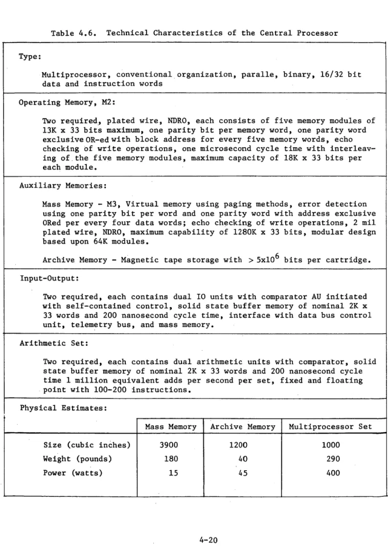
4-6 Technical Characteristics of the Central Processor 4-20
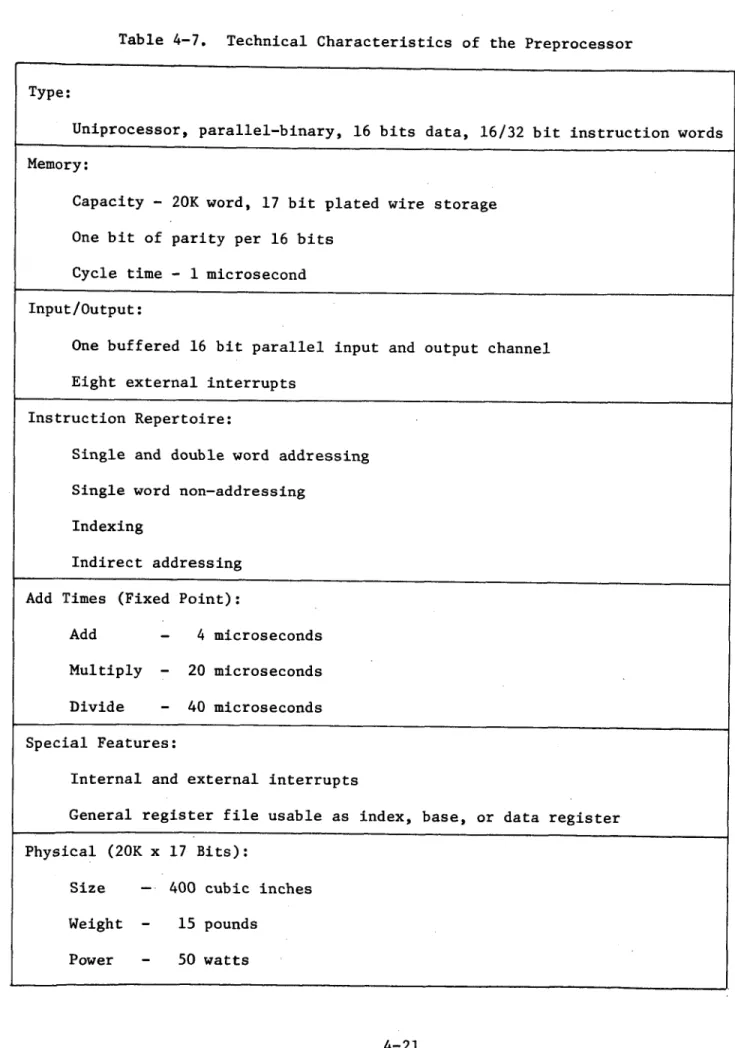
4-7 Technical Characteristics of the Preprocessor 4-21
5-1 Baseline Standards and Conventions . . . 5-4
7-1 Current ADT Accomplishments . · 7-1
7-2 Utilization of Results . . 7-2
-
NorthAmerican Rockwell
PRECEDING PAGE BLANK NOT FIL
Ae
ABBREVIATIONS
Advanced Data System
Advanced Development Technology
Advanced Development Technology Extension Automatic Frequency Control
Automatic Gain Control
Autonetics (Division of North American Rockwell Corporation)
Bandpass Filter Bits Per Second
Computer-Assisted Interactive Resource Scheduling
International Radio Consultative Committee Critical Design Review
Contract End Item
Computer Language for Aeronautics and Space Programming
Command Module (Apollo) Common Pool (of Data)
Central Processor or Circular Polarization Computer Program
Computer Program Contract End Item Computer Program Configuration Item Computer Program Development Facility Computer Program Integration Contractor
(Agency)
Computer Programming Test and Evaluation Change Report
Cathode-Ray Tube (Display) Crew Subsystem
Communications Terminal Breadboard Central Test Facility
DACS dB DBCU dBm dBW DCR DDB Demux DMS DPA DPSK DRSS
Data Acquisition and Control Subassembly Decibel
Data Bus Control Unit
Decibel Referred to One Milli-Watt Decibel Referred to One Watt
Design Change Request Digital Data Bus De-Multiplex(er)
Data Management System Data Processing Assembly Dual Phase Shift Keying Data Relay Satellite System ADS ADT ADTX AFC AGC AN BPF bps CAIRS CCIR CDR CEI CLASP CM COMPOOL CP C.P. CPCEI CPCI CPDF CPIC (A) CPT&E CR CRT CSS CTB CTF
Space Division
9
%
North American Rockwell
ECP EDF EEM EEMP EIRP EMC EMI EOS EOSS EPS ETC/LSS or ECLSS EVA EXT Eb/No FACS FDM FM FQT G&CS GFE GHz GOA HAL HOL HOLM Hz IF IFRU IM IMS IMSIM IOC IOCB IOU I/O IPA IQL IR ISS or IMS/S ITT K-words K-EAPS K-bps KHz
Engineering Change Proposal Experiment Data Facility Engineering Evaluation Model
Engineering Evaluation Model Processor Effective Isotropic Radiated Power Electromagnetic Compatability Electromagnetic Interference Earth Orbital Shuttle
Earth Orbital Space Station Electrical Power Subsystem
Environment Control and Life Support Subsystem
Extra-Vehicular Activity External
Energy Per Bit to Noise Density Ratio Facsimile
Frequency-Division Multiplex
Frequency Modulation Formal Qualification Test Guidance and Control Subsystem Government Furnished Equipment Giga-Hertz
Gated Operational Amplifier
Higher-Order Aerospace Programming Language Higher-Order Language
Higher-Order Language Machine Hertz
Intermediate Frequency In-Flight Replaceable Unit Intermodulation Products Information Management System Information Management Simulation Initial Operational Capability Input-Output Control Block Input-Output Unit
Input-Output
Intermediate Power Amplifier Interactive Query Language Infra-Red
Information (Management) Subsystem International Telephone and Telegraph Thousands of (Computer) Words
Thousands of Equivalent-Add Operations Per Second
Thousands of Bits Per Second Kilohertz
- xiv
Gu
14North
American RockwellLEM Lunar Excursion Module
LM Lunar Module
LNA Low Noise Amplifier
LO Local Oscillator
LPF Low Pass Filter
M1, M2 (Computer) Memory Designation
Mbps Megabits Per Second
MCB Module Control Block
MHz Megahertz
MOF Mission Operations Facility
MOL Manned Orbiting Laboratory
MSC Manned Spacecraft lenter
MSFN Manned Space Flight Network
MSS Modular Space Station
MUX Multiplexer
mW Milli-Watts
MW Microwave
mV Milli-Volts
NF Noise Figure
OBCO On-Board Checkout
OCC Operations Control Center (On-Board)
ODM Operational Data Management
OM Operating Memory
PA Power Amplifier
PCM Pulse Code Modulation
PDR Preliminary Design Review
PL/1 Procedure Language
PM Phase Modulation
PN (PRN). Pseudo Random Noise
ppm Parts Per Million
PQT Preliminary Qualification Tests
PSK Phase Shift Keying
RAM Research and Applications Module
RACU Remote Acquisition and Control Unit
RCS Reaction Control Subsystem
RF Radio Frequency
RHCP- Right-Hand Circular Polarization
RPU Remote Processing Unit
Rx Receive
S&C Standards and Conventions
SCCB Software Configuration Control Board
SCN Specification Change Notice
SD Space Division (of North American Rockwell
Corporation)
9
North American RockwellS/N Signal to Noise Ratio
SOW Statement of Work
SPL Space Programming Language
SRD Step-Recovery Diode
SSCB Solid-State Circuit-Breaker
SSS Structures Subsystem
STE Support Test Equipment
TAV Test and Validation (Programs)
TBD To Be Determined
TCXO Temperature-Controlled Crystal Oscillator
TDA Tunnel Diode Amplifier
TDM Time Division Multiplexing
TDRS Tracking and Data Relay Satellite
TIP' Test and Integration Plan
TLM, TM Telemetry
TOOL Test Operations Oriented Language
TRW Thompson Ramo Woolridge Corporation
TT&C Telemetry, Tracking and Control
TWT Traveling Wave Tube
TWTA Traveling Wave Tube Amplifier
Tx Transmit
USB (E) Unified S-Band (Equipment)
UV Ultra-Violet
VDD Version Description Document
VHF Very High Frequency
VSB Vestigal Side Band
VSWR Voltage Standing Wave Ratio
xyi
Space Division
9
North American RockwellLIST OF INTERIM REPORTS
AA-101 DPA Flow Diagrams, September 1971
AA-102 DPA Throughput and Authority Analysis,
February 1972
AA-103 DPA Configuration Selection, April 1972
AS-lOl Modular Space Station Computer Program
Standards and Conventions, December 1971
AS-102 Modular Space Station Computer Program
Specification Tree, February 1972
AS-103 Modular Space Station Computer Program
Development, Test and Configuration Control Plan, May 1972
AS-104 Modular Space Station Computer-Assisted
Resource Allocations and Utilization Recommendations, June 1972
CTB-101 Concepts for Multiple RF Link
Mechanization, May 1971
CTB-103 Antenna-Mounted Electronics Component
Design, October 1971
CTB-105/106 CTB Integration and Test and Operations
Manual, June 1972
DB-101 Parametric Data for Bus Design, May 1971
DB-103 Component Performance Requirements,
Schematics and Layout Drawings, December 1971
DB-104 Digital Data Bus Breadboard Final Report,
May 1972
DD-102 Modular Space Station Data
Processing-Assembly Parametric Evaluation of Subsystems Input/Output Interface, June 1971
Space
Division
'
North American Rockwell
DD-103 DP-101 DP-102 DP-103 DP-104 DP-105 DP-106 DP-107 DP-108 DP-109 DP-110 EL-277 IB-101 ICD #TRW 20549 ICD #AN 26465 MD-101 . RF-101
Modular Space Station Data Acquisition and Control Subassembly Model Configuration
(SD 71-233), July 1971
Data Processing Assembly Configuration (Preliminary), June 1971
Data Processing Assembly Supervisor Specification, May 1972
DPA Processor Final Description, May 1972 EEM DMS Processor Development Plan, June 1972 Data Acquisition and Control Redundancy Concepts, August 1971
Application of Redundancy Concepts to DPA, January 1971
Data Acquisition and Control Subassembly Breadboard Design Requirements, October 1971 Data Bus Control Unit Performance
Requirements, January 1972
Data Bus Control Design Reports, March 1971 DBCU Acceptance Report (to be published) Bulk Storage Development Plan
DPA Internal Flow and Traffic Pattern, May 28, 1971
Interface Control Document - Data Bus Modem/RACU, Revision A, January 17, 1972 Interface Control Document - Data Bus Controller Unit to Buffer I/O, Revision January 21, 1972
Mass Memory Parametric Data
Modular Space Station Communications Terminal Breadboard Preliminary System Specification, October 1971
- xviii
0 4
North American Rockwell
Central Processor Operational Analysis, September 30, 1971
Central Processor Memory Organization and Internal Bus Design, December 30, 1971 Automatic Control and Onboard Checkout Final Study Report
SA-101
SA-102
Space Division
9%
North American Rockwell
1.0 INTRODUCTION
The NASA Modular Space Station Preliminary Definition Study (NAS9-9953) included a special emphasis task to develop selected breadboards and assembly specifications to evaluate and further define the advanced concepts incorpor-ated in the Modular Space Station Program (MSS) information subsystem (ISS).
The Space Station Program requirements for near-continuous MSS-to-ground communications, for extended automation of spacecraft subsystem functions, and for expanded autonomy to plan, schedule, and conduct a wide spectrum of exper-iment operations resulted in an ISS concept that included a K-band data relay satellite communications link, a sophisticated on-board data management system,
and an interactive man-machine decision-aid capability. Among other items, the ISS required a 10-megabit-per-second, time-shared data bus system; a dual multiprocessor central computation facility with a complex software assembly
and a 25-watt K-band power amplifier.
Since much of the success of the Space Station Program relied upon the capability of the on-board ISS, and since several of these concepts were untried or unproven at that time, the Information Management System (IMS)
Advanced Development Technology (ADT) task was funded as a 17-month integrated effort to develop or further define actual equipment breadboards that could be tested and evaluated by NASA (ISC), starting in July 1972. The ADT task was to run concurrently with, support, and track the MSS Preliminary Definition
Study; due to lead-time factors, the ADT task was extended in time beyond the MSS study itself so that refinements could be incorporated into the demonstra-tion breadboard equipments to more closely represent MSS requirements.
The influence of the MSS configuration can be seen by examining Figure
1-1. A central core module provides multiple docking ports to accept other
special-purpose modules. The core contains the guidance and attitude stabil-ization/control and the fuel cell power equipments and is divided into two isolatable pressure volumes separated by an airlock. At one end is the solar array power module, which also contains repressurization stores. The four standard modules are internally configured to provide the functions and work-ing/sleeping areas as labeled. An additional cargo module and one or more
research application modules (RAM),specialized for selected experiment
disci-plines, can be docked to any of the five other ports.
There are several aspects that impact the ISS. First, except for the power module, the basic configuration is that of two half-space stations,
either one of which can maintain full operational capability even with one pressure volume uninhabitable or unusable for some reason. It follows that
the crew's command/control capability (represented by the control center areas in SM-1 and SM-4) must also be dual and capable of operating independently in case of failure or cooperatively under normal conditions. The control center includes the central computer, the operations console, the baseband RF
commun-ications, and the internal telephone/television distribution control.
Space
Division
North
American
Rockwell
"3~~~~~~~~~u)
lr,~~~~~~~r O Cd Co-0
r-4(20~~~~~~~~
.r-N rM4~~~~~r a~~~~~~~~ 00 * 2 z -IN
-w2 -. i t~~~~~E
~
~
I r-I *rI mCD &:~'·
·"'b P '4: 1-2~· SD 72-SA-0114-19|,
Space Division
Gu
North American Rockwell
Second, the MSS is assembled in orbit by successive launches via the orbiter, a procedure that requires many days. The impact is that the ISS must
(1) be operable as soon as SM-1 is joined to the core/power modules to auto-matically control the unmanned station to this point, (2) be extended to each new module as it is docked without modification other than connecting the data bus, and (3) check out and verify the equipment functions of each module after orbital assembly. This guideline of having one spacecraft subsystem verify,
certify, and control all other subsystems is indeed unique, and it imposes a failure-tolerance requirement on the ISS that is one level greater than for the other equipments.
Third, communication with the data relay satellite could not require
special attitude maneuvers or constraints to the station flight mode. This communication was implemented by installing two antenna packages on the out-board end of SM-1 and SM-4; the design concept was that the K-band power
amplifier and K-band receiver were to be mounted external to the pressure volume (to reduce RF power losses due to cables, connectors, etc.), and that this unit would not have active thermal control. This concept, also unique, was to be demonstrated.
Figure 1-2 shows some of the more important design features of the MSS/ information subsystem. Dual control centers, each having a central processor (which is, itself, dual redundant), are both linked by a quad redundant data bus that provides a dual redundant connection to every piece of active equip-ment. Communications incorporate redundant K-band (1 duplex channel), S-band
(3 duplex channels), and VHF (1 duplex channel). 1.1 OVERVIEW
The IMS ADT task was conceived to be one step of a long-range plan (Figure 1-3) to culminate in the delivery of a data management system (DMS) prototype, including the computer (multiprocessor), operations console,
executive software, and automatic communications capabilities. This prototype DMS would be used by NASA-MSC for conducting system integration/evaluation tests (including other spacecraft subsystems) and for developing the proced-ures, programs, and data base needed to automate, detect, and isolate failproced-ures, to conduct maintenance and repair simulations on all spacecraft subsystems, and to develop man-machine interactive operations and procedures. The dashed line at the left indicates the scope of the IMS ADT task in contributing to this long-range plan.
The IMS ADT task was divided into seven subtasks (Figure 1-4) to estab-lish contract responsibilities. Their time-phased relationship to the Modular Space Station Definition (4.1.2), Command/Control (4.1.4) and Design (4.1.6) tasks is indicated by the arrows. The ADT subtasks (4.2.1 through 4.2.7) included operating breadboard models of the 10-megabit-per-second data bus and
the K-band communications terminal antenna-mounted electronics. The remaining
five subtasks were studies to further define the data processing and software assemblies to result in performance specifications and development plans/sched-ules for additional breadboard or prototype equipments. The dashed-line titles represent some of the expected future ADT subtasks that are considered time-critical to the Space Station Program.
1-3
Space
Division
i
North
American
Rockwell
ro
0 0 U) 4: ui LU U-z w O U) Cr -i U) w~mt
V V° cc (n 10 Zo
0J o Z -j -J< O <0 G G Z ix:cr H H 3 Z z 0 ow W O U· tD D a: J 0 a -j 0. 0 6: < <> * * S 01)1 u U n < 0 0- z z < O m w . < cr F- 4 ZH< Z F S 2 OZ O 00 <0 0 J S: JC LU (D cz z y~ . o u 62< C z Z~-Z o ZI-Z LAJ~~~~~~~~~~~~~~, JA o r X m eo Z 2< 0 0CD ZXO wW I: F : \ I < , 0 0 zoo~~~~~~~~~~~~~OC U) OW OO > G O U-G 0 ) Cw cw I °Z < wUH W o0 a0 E -a- 0 cc O CL o < . 0 0 o CCE Zr : Z _i : 1-4 SD 72-SA-0114-1 0 0 1-4 4) r4 P 4oSpace
Division
North
American
Rockwell
Zi z,oT
c-a5
A, .. ,~~r
2i~~~~i.
o _5
© z~~~~ cu B~~~ ! Io 3 gcw~~~~~~~ z I CALL)- 0~~~~0Z
I~ ~
~ ~
~ ~
~ ~
~
I~~,
Z0o u Ml g a,~< 0 i--~
0 Z~~~~~ 0 <l9
~~~~~~~~~~~~~~~~~~~4-1Oo1-5
~
~
~
yr
6~~~~~)uz
-a~LLW
uluw aC WX O of zzj
Um3b
S U)~~~t 0 Ce 1-5 SD 72-SA-0114-1 (N a. C-(N4Space
Division
North
American
Rockwell
I
I~~
~
~~i
i
]'
I1
I
;I
I
I
I
*
I
I
_~~~~L
i111
(u~~~~~~~~~~~~~~~~~~~~~~~~~~~~~~~~~~~~~~~~~~~~~~~CI
:
1 zO
o~~~n -ui u I II 010 LU (n SI- jO Ln II2
'
o
J
IeZ
I
I
I
I
i~
~I
~2
I
<I
I
-I
>-§ LU all u allIa~~~
0rl~~~~ IQI
I(O
IQ
co . 1 31 1>1 10 II rr U ct ;gcJj
j
OI
nI
I
, Id)I jz~
~
~
0J LU0 "' 1'0
(~~~~~~~~~~I
c:3~~~~I
lu-Iu /~ 0 <co~~~~~~~~~~~~~~~~~~~~~~~~~~~~~~~~~c LU LU~~~~~ LULLU4- LLUUZ
C:d!
~~
2'
I
uj
<
I
W rye /~ 0 e L -JC Uc<
~~,
0
* 0 0 0 * * * I x co L oe
-~~~~Z
w QmCO ,a Z 0 kA LU LU C O Qu =) I-- r>0z Cz
u
Ol
"'
~
~O
LY 0 LUL ~.0
u_
{3o 11 0 0 1 10n1
1-6
SD 72-SA-0114-1Space Division
9
North American Rockwell
The contractor (NR-SD) elected to subcontract major portions of the ADT task to encourage industry participation and maximize the benefit of consid-ering a variety of viewpoints from specialists. The contractual subtasks
(4.2.1 through 4.2.7) were further divided into many small jobs, which were compared to potential subcontractor or NR capabilities and then assembled into work packages for negotiation and administrative control. NR-SD retained the role of systems engineering and technical management, and
retained some technical jobs that could best be accomplished with the cooper-ation of the MSS Informcooper-ation Systems staff and other MSS subsystem design staff. The remainder of the jobs were allocated to subcontractors as shown in Figure 1-5. The contracting agency selected TRW to supply the GFE equip-ment.
It was realized at the onset that the initially negotiated subcontractor work packages (Statement of Work) would have unforeseeable impacts as the ADT and MSS design studies proceeded. To accommodate these impacts, NR used a
flexible management approach, as shown in Figure 1-6. The initial work pack-ages, interim results of progressing studies, and modifications to the MSS Guidelines and Constraints were reviewed periodically by the NASA IMS Working Group, in regular subcontractor technical interchange meetings and in sched-uled breadboard concept and design reviews. These meetings, attended by all involved subcontractors and by cognizant NASA-MSC personnel, provided a forum
to critique the on-going efforts. Action items were made part of the minutes of these meetings, which in turn were reassessed and developed as technical
directive letters to modify or clarify the individual dual subcontractors' statement of work without any cost impact. The success of this approach was
due to the very cooperative participation of both subcontractor and NSC personnel.
1-7
Space
Division
North American Rockwellz
O
O>
z
I--2 u- LL L/) LLV Z I LUL -Z @ LUQI-z a-0 _ I O0'
i:_ I Z _ z -J U z I 0I--
I
'ZoDI
I
I
z C3
LU u VL Z W U Fe. < z z)Z -4 Z I- OC z Lu u LU -<o UI-co
W0~c
Yz z u > WLU UI
O 0L t/:U e. I--* -_ _ < ,, 13I< U * 0 0 S z 0 LI, W L.0
LI, 0z
O-Z
z
LUlZ
O
* 0 Z -* 0 SD 72-SA-0114-19%
z C, Z.--<
Z LU U I I UU
, "c'Z Ua-LU I 8m 0 LL;6 0; Ce C o 4,i N .,.~ o o $4 4 oU U -I .r4 Pk 1-8]
Space
Division
@
North
American
Rockwell
/
/
/
/
/
I,
/
/
/
/
/
/
0 Z UV
Z
YI Ouoz
Qu' M.LL Z) I 0 z LAW
U;
caeZ LS> .- LUa -ZO C Z V OWo co - UV) U CU Z c c co co co 1-9 SD 72-SA-0114-1 0 a CN U, -l mI
/
I
I
I
/
4J a) u: E-00 W to -4 a) o 0J > r-0.0,
N,
I
/.
I
I--~~~~~~ UO
z C; -002 Vco Ln ·) a) :1 o .,,z
I mI U.J\-
-Space Division
9
4
North American Rockwell2.0 COMMUNICATIONS TERMINAL BREADBOARD
This section summarizes the results of an 18-month study and hardware design and test whose final objective was to demonstrate a technique for integrating the modular space station (MSS) external communications equipment with a high gain parabolic antenna and to demonstrate its capability to
perform the MSS communications operations. This program includes preliminary analysis to define the design of an MSS concept that would be compatible with other program elements such as the earth orbital shuttle (EOS) and the tracking and data relay satellite (TDRS). Details of this analysis, the design concept of an overall communications terminal breadboard (CTB), and the design details and test results of the delivered external RF package are included in Volume II of the final report.
2.1 SUMMARY
The MSS total communications terminal includes a complex of equipment operating in three frequency bands - VHF, S, and K. Each band is used to provide specific communications links with a multiplicity of external terminals and a complex of baseband signals. These links and their signal transfer requirements are defined in Table 2-1 and Figure 2-1.
Operation of the communications system to provide the capability for multiple link frequency performance is proposed by a design that incorporates RF and baseband switching. This design is based on the MSS Phase B concept to mount the K and S-band RF power amplifiers and RF receiver preamplifiers as close to their antennas as possible. In the case of the K-band system, this involves the location of these equipments on the external, steerable, parabolic antenna. By providing up and down conversion to the K-band trans-mitter and receiver from S-band, low-level RF signals can be routed from the internal S-band equipment over coaxial cables to the antenna mounted equipment. In a similar manner, the S-band system using S-band power amplifiers and receiver front ends mounted close to the semi-directive antennas can be fed at low levels via coaxial cables. Efficiency of overall systems is thus improved by avoiding the RF cable losses that would result at the higher powers and higher frequencies (for the K-band system).
These concepts required the development of a K-band transmitter/receiver package capable of being operated in a space environment and of being
mechanically and electrically interfaced with a five-foot parabolic antenna.
Development of a concept for multiple RF link mechanization was also required.
The first task resulted in a concept for multiple RF link mechanization. Provision is made to switch between the five separate duplex RF channels which link the MSS to:
Space Division
9
North American Rockwell
1. Tracking and data relay satellite (TDRS)
2. Earth orbital shuttle (EOS)
3. Two research application modules (RAM's)
4. Ground stations of the MSFN
Both baseband and RF switching were considered necessary to provide proper data to the desired link. Utilization of a PIN diode RF switching matrix results in a design concept for a lightweight, compact, reliable RF switching system with presently available hardware. Baseband switching and multiplexing concepts were also analyzed and recommended systems defined.
2.2 CTB GENERAL DESCRIPTION
A complete set of requirements were developed for a communications terminal breadboard (CTB) that can be used as a test bed for evaluation of the MSS terminal concept. Figure 2-2 shows the block diagram of this overall communication terminal breadboard. The antenna-mounted electronics subassembly was designed, developed, and delivered as an operating unit to these require-ments. Implementation of a complete system requires the mechanization and
interconnection of other subassemblies that include an antenna system, S-band
converters to and from baseband, multiplexing and demultiplexing equipment, and a baseband switching system. Requirements for all of these subassemblies were developed and can be used to obtain available hardware. The antenna-mounted electronics subassembly is supplied with the necessary interconnect cables and control display unit to operate this equipment. Figure 2-3 identifies all of this hardware. A concept of the overall breadboard configuration is displayed in Figure 2-4. The overall CTB requirements definitions form the basis for ensuring that the ultimate CTB will represent
a logical development of requirements and concepts. It should be emphasized that the characteristics and definitions are by no means frozen. They may vary to reflect any changes in the station concept as it evolves.
The antenna-mounted electronics subassembly contains a K-band (14.65 GHz) receiver mounted in an enclosure designed for operation in a space environment. The K-band equipment is designed to interface with S-band frequencies,
specifically compatible with the LEM transceiver. Thus, a complete operating breadboard at K-band can be assembled by connecting and mounting the antenna mounted electronics subassembly to an antenna and connecting the K-band
transmitter input to the LEM transmitter output at 2.2825 GHz and the K-band receiver output to the LEM receiver input at 2.1018 GHz. Up and down conversion and the necessary amplification are provided in the K-band equipment package.
The antenna mounted RF electronics subassembly, shown in Figure 2-5, has the following major characteristics:
2-2
OD North American Rockwell Transmitter Output frequency RF power output (1) RF bandwidth Input frequency
Input RF drive required Input RF impedance
14.65 GHz
6 watts (one TWT); 20 watts (two TWT's) 200 MHz
2.2825 GHz 1 MW
50 ohms
(1) When one TWT power amplifier is used. When two are connected in parallel, power output will be a minimum of 20 watts. Single TWT operation operated in the two tube circuit results in a
3 db loss in the hybrid circuit.
Receiver
Input frequency 13.6 GHz
Input RF signal level 83 dBm
RF bandwidth 200 MHz
Receiver system noise <7 dB
figure
Output frequency 2.1018 GHz
Output S-band power level -33 dBm (min.)
Output RF impedance 50 ohms
2.3 TECHNOLOGY GOALS
Detailed design of the antenna-mounted electronics subassembly was based on the performance requirements that were structured from a set of technological goals established by NASA. Evaluation of this equipment and its operation will define the adequacy of these concepts for application to the MSS communications terminal design. An effective laboratory and operational test program and the resultant evaluation will provide data for avoidance of future design and operational problems.
The total CTB can be expanded to address other technical and operational problems associated with future concepts and practices for the MSS communication
terminal. Addition of RF switching, S-band terminals, and the associated baseband switching would allow evaluation of frequency spectrum management, simultaneous multiple links, and EMI problems.
Space
Division
i
North
American
Rockwell
,t zLU U.i r W 2-4 *U.
0 Z0 --0 Zo
0 .0 2-48> n; ._ SD 72-SA-0114-1z
.- zv ·' UO0D%
North American Rockwell
"Table 2-1. External Communication Data Characteristics:
Ranging c , a E E Q , 0 E .c d 0 ¢ -_ 4) 0 X d ) . O > ( _ o 0 o0 P rU
Detached RAM S-band (1) 300- 10 0. 5
4000 Hz kbps mbps
o
Shuttle orbiter S-band (1) 300- 50 0. 5 0. 5
.o 4000 Hz kbps mbps mbps
u MSFN ground S-band (3) 300- 4. 5 500 500 2. 0 1.0 200 0. 5
o terminal direct 4000 Hz MHz kbps kbps mbps kbps bps mbps
co Ground terminal VHF (1) 300- 10
o via TDRS 4000 Hz kbps
Ground terminal K-band (3) 300- 4. 5 500 500 2.0 1.0 200 0. 5 0. 5
via TDRS 4000 Hz MHz kbps kbps mbps kbps bps MHz mbps
EVA VHF (1)
300-4000 Hz
Detached RAM S-band (1) 300- 2.9 50 500 Part 0. 5
4000 Hz MHz kbps kbps of mbps
system
E TLM
' Shuttle orbiter S-band (1) 300- 1.0 0. 5 0. 5
o 4000 Hz kbps mbps mbps
d
MSFN Ground S-band (4)* 300 - 500 1.0 1.0 0. 5 s Terminal Direct 4000 Hz kbps kbps kbps mbps U W Ground Terminal VHF (1) 300- 1.0 o via TDRS 4000 Hz kbpsGround Terminal K-band (4)* 300- 500 1.0 1. 0
via TDRS 4000 Hz kbps kbps kbps
EVA VHF (1) 300- 200
4000 Hz bps
*One of the four voice channels - ground to MSS - is a high-fidelity channel 30-10, 000 Hz for entertainment.
Space
Division
9y
North
American
Rockwell
3Wtld "011VIS0
r.) U I ± INni 2-6/wtlolnn_
_
"
l
2-6~rl
SD 72-SA-0114-1 W31SASSpace
Division
%
North American Rockwell -4 t 0<< o Hu I < z <z ) U z x o -Z 00a OH : X Z 7: X W 0 -XJ UU-Z -w -0. ¢ H x U)" U) W) o o *0 <U z zo'ZO E- , l o: U o 0O H: H CC 0 0C E 0 > FE-. 0 > -le H0 y = z -C. U. R 0 U) W o W 0 z -=- 0 0 <0- X " U 0 0 0 00 0 0 U H .U U z r ) 04: H W u)C W U) ><tO L 4UU)Z <00H0UzIU a > > U U Q U_ Cx W Z Z uX U U): z a oo CZ x cg U-, Wz U > U W -W W. W Z¢ZE H U) U) W U ¢U) 00000 0 W~Cl)
HH E)] U) LLQ. Hz ZZ Z cE U v U H: LI. i~ E " L. JZ A:; z : z U )~W U L] 0 X W U U 0 *-0 -Z "i QF Lu W =.-eLno : LI. U. a LI] v LI] 0g az LI L~~-
, c ,za w ODax uo = u) L. U 0 U) c Lu H o o0o00 0 00 2- 7 SD 72-SA-0114-1i$
91 H '-q -40
Cn w5 A. I, 1u a U ZZL ZU WZZ U3 uW En W 044 U Z . ' . E- WU) z E (f , U) > -n M U) HUV) ZU¢ HLLIan VA"= >-ZLU U) e U)I
3 U '44 ,-4 4Z 0 'r-0) [-q (4 10 cr 4V) 0h W1 -H U] = 4-4 0 U) -x 0 . .,-U) 0. U) .) 0 U H W e . < x = U 4 -ISpace
Division
North American Rockwell E Ce Lu W E 3 L C D k^ I. -Uz
-z~~ Lu z Lu ---- C IU- C3 Q" U Lu L V3~ LU .-x,¥
Z w. ,Z z W z v "I\ I0~_~~~~e
'..
0 -' z a 2-8 SD 72-SA-0114-1 u, a-cL01
a z o o IZWA
0
o
V) V-2 Caz U < Lu IZ ZO O-Zu X 'a t O~~~~~ LL -W Cie'11ol
13
]"I
l
-jI eLI
LOIB. I>~~~~>I _I_
_ U~~
00~o -I z Luz
u11 0 u1 olx z I-c Iz I ; :: > D > U 0 0 0 I I U :: u I <C-J
uwe- z u Lu z 0 OZ ,:EI
--I 0 o U) 4J >1 0 cO 0 .4J 0)co 14 C-Lu 0z .Z L -Z -1 .H TZ[I
11 :z• Spac e Divisio n Nort h America n Rockwel l o
n
Q J M cf l A S C J ffl o , > , 1— 1 .n L i 1 ) W w m ^ o 3 C O O ) u •H a 0 M J-J u 0 1 i H w -a <u •w a 3 O S 3 w c c 0 ) •u c <d M H u . L O C N <u u 3 M O J (J 01 fe 4-1 (J a) C a o O H O J i-J C H T 3 a (0 bO C •H u a 3 O S 3 *N r» cu •H > 0 ) 3 r r H H a a P M S D 72-SA-0114-1Space Division
By• North American Rockwell
As indicated by the technology goals, CTB/antenna compatibility and techniques for automatic checkout and control can be investigated by means of the equipment specified herein.
2.4 HISTORY
At the inception of this program, the CTB was conceived as an S-band system with a solid-state, 20-watt transmitter power amplifier. With the development of the TDRS concept as the high-data rate relay satellite for MSS to ground, it was decided to change the emphasis for operational frequency to K-band - the TDRS frequency band. S-band equipment of the type proposed was already available as off-the-shelf type equipment. K-band equipment with a 20-watt RF transmitter power output and low noise K-band receiver equipment needed to be developed and evaluated. These factors led to the decision to design and build a K-band system after the statement of work had been negotiated with ITT for the CTB. Final negotiations with MSC and ITT resulted in reduction of analysis tasks and complete emphasis on the development, design, production, test, and delivery of the K-band, antenna-mounted RF electronics assembly. Full use was made of concept development activity in the specification of K-band hardware. This more closely followed
the intent of the program - the demonstration of required new technologies.
2-10
Space Division
9ft
North Amenrican Rockwell3.0 DIGITAL DATA BUS BREADBOARD 3.1 DACS REQUIREMENTS SUMMARY
In the Modular space station, the data processing assembly (DPA) is highly distributed. The concept of two. pressure volumes results in the division of the central processor between two control centers in such a way that the computations associated with station operations and experiments can be performed in either volume. Similarly, the subsystems and experiments are divided between the two pressure volumes; and what is more, the subsystems are distributed throughout the modules that make up a 6-man or a 12-man configuration. Some of these subsystems require on-the-spot computations; these are provided in the DPA design by remote processing units (RPU's). All subsystems require computational support from the DPA. Therefore, the DPA must acquire data from these distributed subsystems and return data, instructions, and commands.
A significant portion of the ADT effort has been devoted to the analysis and breadboarding of a data acquisition and control subassembly (DACS) to provide the necessary interflow of data between the two. central processors, the subsystems and the experiment equipment. The DACS has been defined to include the digital data bus (DDB), the data bus control unit (DBCU), and the remote acquisition and control unit (RACU). Two of these have been analyzed and breadboarded as a part of the ADT effort; these are the DBCU and the DDB.
Figure 3-1 presents the task breakdown and flow which was followed in ultimately delivering breadboards of the DBCU and the DDB. Note that a RACU/ RPU breadboard is government-furnished equipment (GFE).
The primary objective of the DACS breadboard is to verify the digital data bus concept for the modular space station. It will demonstrate the availability of technology to provide accuracy of data transfer, reconfigurability, failure tolerance, long useful life, and standardization of interfaces.
The data acquisition and control analyses began with a theoretical analysis of the parameters pertinent to the design and usage of data buses. The result of this analysis was a design handbook covering the significant aspects of wide-band digital and analog data buses. A model was defined for the data acquisi-tion and control subassembly (DACS) breadboard. The purpose of this definiacquisi-tion was to provide data to serve as a basis for the design of a DACS breadboard. It
identifies the objectives of the breadboard, some potential vehicle related design problems, and a simplified implementation concept.
The analysis of DACS redundancy concepts covers the advantages and dis-advantages of a general range of concepts and methods applicable to the DACS. Recommendations of methods were made and justified. The overriding require-ments were found to be the single and triple failure tolerance requirerequire-ments and
Space
Division
9
North
American
Rockwell
-o V 4-) -- -tok ' :~~~o I43-2
.FsB~~~~~~~~~II~~
443-2
~c
SD 72-SA-0114-10,•k
NorthAmerican
Rockwell
the physical separation of redundant subsystems into pressure isolatable volumes.
The recommendations for the degree, level, and type of redundancy for each DACS element are presented in Vol. III. These recommendations include the split between hardware and/or software techniques, the utilization of
error protection coding, the replacement/repair methods and a definition of
the replaceable items, and the rationale for each selected candidate DACS element.
The following redundancy requirements were imposed on the station subsystems:
1. A capability must be provided for each non-critical function to fail safe for the first failure.
2. For a critical function a capability must be provided for:
a. Full operation subsequent to a first failure (fail operational)
b. Reduced or out-of-spec performance subsequent to a third
failure (fail emergency)
3. Time critical functions require active (on-line continuous operation)
redundancy. Non-time critical functions require at least standby redundancy (wired in and activated with automatic or manual
switchover.)
Figure 3-2 presents the recommended implementation of the DACS that will
satisfy the failure criteria (redundancy requirements). The RACU interconnect is shown for one complete critical subsystem functional loop model Type B.
Only a small portion of the data bus assembly DB-1 is shown. The RACU
inter-connect, as recommended and pictured, allows two of the RACU's and their
associated subsystem functional loop to be in a standby mode while the other two are active. This is true for both time-critical and non-time critical models of Type B.
The overall recommended DACS utilizes parallel and serial redundancy in many combinations. Distributed and functional redundancy are utilized to the extent possible. BITE is used extensively to aid in failure detection and isolation. Serial redundancy is used for transient error protection throughout the subsystem. The DPA multiprocessor and its software is utilized for all higher level BITE analysis, failure determination, fault isolation and crew notification for repair by replacement.
This recommended DACS configuration is very sensitive to the two basic
overriding-requirements; these are the single- and triple-failure tolerance requirements and the separation of all redundant items into two pressure isolatable volumes. The recommendations are also quite sensitive to the IFRU maintenance philosophy and somewhat sensitive to the other critical function requirements.
Space
Division
North
American
Rockwell
L) .v_4 to .H 0 o, U) u Cv "O 0. 3-4 SD 72-SA-0114-1.North American Rockwell
3.2 DACS BREADBOARD DESIGN
The DACS breadboard is an engineering model that is representative of the concepts for the data acquisition and control function for the data processing assembly of the modular space station. NASA defines a breadboard as a unit which performs the same functions according to the same characteristics as
those defined by the hardware design.
A data acquisition and control subsystem is a semi-autonomous subsystem that provides controlled communication between a large number of .remote. locations and a control location. Insofar as possible, the DACS breadboard is an engineering model representative of the concepts for the data acquisi-tion and control subassembly for the data processing assemEly of the Modular Space Station. The DACS breadboard also provides a test bed for operational performance evaluation of numerous concepts for this type subsystem oriented toward the specific needs and requirements imposed by the Modular Space Station.
The overall breadboard concept for the DACS is a highly flexible, con-figuration-independent, building-block approach. This approach allows a large number of different DACS configurations to be assembled as an operating data
acquisition and control subsystem breadboard. Each configuration concept can
then be operated, tested, and evaluated for overall DACS concept and performance suitability.
Six basic types of units, plus additional test equipment comprise the DACS breadboard. These are the following:
a) Breadboard Modem Unit(s)
b) Core Bus Interface Unit(s)
c) Equipment Bus Interface Unit(s)
d) Interconnecting Cable(s)
e) Breadboard RACU(s)
f) Breadboard DBCU
g) Special Breadboard Test Equipment
The DACS breadboard was designed within the limits of the following constraints:
a) The DACS breadboard shall operate as a self-contained entity without
the need for external intervention but under external command, control and influence.
b) Operation of the DACS breadboard will be internally controlled by the
Data Bus Control Unit (DBCU).
c) All control interaction with the DACS breadboard from external
sources will be through the DBCU.
d) All breadboard performance evaluation will be provided external to the RACU's, DBCU's, and the data bus breadboard units.
e) The breadboard shall operate with a fixed word length of 8 bits.
f) The breadboard shall operate with a variable size message structure
in all modes, of from zero to 124 data words.
g) _Hardware error detectionand encoding shall be provided.
h) The breadboard units will contain provisions for both fixed and
Space Division
'0%
1North
American Rockwelli) All hardware breadboard units shall have a standard
disconnect/inter-connect scheme for ease of assembly into various configurations.
j) A method (or methods) shall be provided for simulating faults within
the breadboard units.
k) Provision for test equipment and/or panels, for determining breadboard
performance, shall be made.
1) All breadboards will be non-redundant; redundant breadboard operation
will be achieved through the use of multiple breadboard units in redundant configurations, and DBCU/Test Processor operational control programs and interaction.
m) RACU and DBCU breadboards shall have internal power supplies operating from the primary power source.
The DACS breadboard was designed with the following considerations for hardware error protection.
a) Hardware shall be provided in both RACU and DBCU breadboard units
to perform error protective encoding and detecting on a word or message basis. Correction is not necessary for the DACS breadboard since this
can be evaluated off-line if desired.
b) The encoding or non-encoding of the data shall be selectable by
external control.
c) Provisions shall be made to allow other coding schemes generated and
detected external to RACU or DBCU to be passed through the RACU or DBCU.
d) The data so encoded shall be passed through to external devices in
either the encoded or decoded from, or both, for other evaluation, and vice versa.
The data bus breadboard shall be designed within the limits of the following constraints:
a) The data bus breadboard shall be a self-contained time-division
multiplexed communication link utilizing pulse code modulation over a hardwired transmission path.
b) Bi-phase level (Manchester) data encoding will be utilized by the breadboard for transmitting data and control bits.
c) The nominal operating frequency is 10 megabits per second.
d) The longest data source to sink distance is 400 feet.
e) The longest non-interrupted line segment is 125 feet.
f) The number of equipments utilizing the data bus assembly in the
operating system total less than 150.
The breadboard modem units was designed within the limits of the follow-ing constraints:
a) Breadboard modem units include all circuitry necessary for bi-phase
level-modulation and demodulation, clock recovery from the bi-phase
level modulated signal, bit timing, preamble decoding, and bus usage by a RACU or DBCU.
3-6
9|,
Space Division
01%
North American Rockwell
b) Breadboard modem units shall operate in a half or full duplex mode. c) Breadboard modem units shall have the capability whereby the output
power delivered to the line can be externally adjusted through a limited range including the minimum for data bus operation.
d) The breadboard modem unit interface with other DACS breadboard elements
consists of serial digital NRZ data, serial digital clock signals and various DC control signals.
e) Equipments utilizing the breadboard modem units will be assumed in close physical proximity, i.e., less than five feet from the modem. The RACU breadboard was designed with the following constraints:
a) The RACU breadboard shall provide the standard interface between the digital data bus modem breadboard and a simulated subsystem functional loop.
b) The RACU breadboard shall contain the circuitry necessary to accept standard format serial digital data and clock signals from the bread-board modem, to convert the data to signals which are compatible with the subsystem requirements, to generate the required control signals for both the subsystem and for data bus usage, to provide buffer storage for subsystem data,. and to provide subsystem data to the bus on command converted to a standard serial digital format.
c) The RACU breadboard shall be mechanized to respond to two types of
messages as listed below:
(1) Message A - Transmit Data to DBCU
(2) Message B - Receive Data/Commands from DBCU
Responses shall be of three types; no response, acknowledge response, and acknowledge and accept DBCU verification.
d) Each RACU breadboard shall have two input (receive) interfaces and
two output (transmit) interfaces with the data bus breadboard modem(s).
e) The RACU/modem interfaces shall have..independent address recognition
circuitry-but are not required to have independent control.
f) A provision shall be made for an external test interface in serial digital form consisting of the data received via the data bus (output) and accepting data for transmission via the data bus (input).
g) The external serial digital test interface shall have provision for
parity generation of data at its input or not, and similarly parity checking the output data or not, externally selectable.
h) Internal data word buffer storage of 128 words minimum shall be
provided for input and output messages.
i) Data transfer to and from the breadboard modem shall operate at a nominal frequency of ten megabits per second.
j) The RACU breadboard shall operate at appropriate time from three clock
sources; either the receive clock from the modem, its own internal clock, or an external clock source via the test interface.
k) A subsystem functional loop simulator interface shall have provision for variable numbers of DC analog and discrete signals to be
multiplexed at varying sample rates, converted to digital form, and formatted.
Space Division
%
North American Rockwell
1) Special provision for local indication. of responses to non-data
commands from the DBCU should be considered.
m) Provision shall be made for an external preprocessor interface. n) RACU addresses shall be externally pre-set.
o) All
RACU
operation will be under higher level control by the DBCU.Operation will be specified by the DBCU commands in each message. RACU operational sequences can be performed by hardware and/or software techniques.
p) A provision for variable decoding of DBCU commands shall be included to allow changing RACU operational modes and command responses. The data bus control unit breadboard shall be designed within the limits of the following constraints:
a) The DBCU shall provide all command. and control capabilities for fully
exercising the DACS breadboard.
b) The DBCU breadboard shall contain the circuitry necessary to originate
and control all messages for the DACS breadboard, to communicate with RACU breadboards via the breadboard modem units and data bus and to
operate the DACS breadboard with or without test processor interaction.
c) Two types of messages shall be originated by the DBCU breadboard as
listed below:
(1) Message A - Request Data from an RACU
(2) Message B - Transmit. Data/command. to an RACU
d) The breadboard DBCU shall have dual, switch.selectable, interface
capability for communicating with.breadboard modem units.
e) Provision shall be included for an external test I/O interface con-sisting of serial digital data for transmission to RACU's and data received from RACU's.
f) The external serial digital test interface shall have provision.,for
parity.generation and detection of I/O data or not, externally
selectable.
g) Internal data word storage shall be..provided for message data sequences and buffering (minimum size of. 128 words).
h) Data transfer to and from the breadboard modem units shall operate at a nominal frequency of ten megabits per second.
i) The DBCU breadboard shall operate at appropriate times from any of three clock sources; the receive clock from the modem, an internal clock source, or an external clock source via.the test interface.
j) Message-generation shall be under internal program control, including
such message options and factors as.message type, message size, RACU
acknowledge,.command.verification, data retransmission, procedures for
operation with errors detected.and improper response conditions, and interaction with external equipments.
k) The internal DBCU breadboard operational program shall be both externally selectable and changeable via the test processor, test panel and breadboard user.
1) A test processor and test panel interface shall be provided for parallel and/or serial digital.data transfer and DBCU (and therefore
DACS breadboard) higher level control.
3-8
9|r
Space Division
North American Rockwell
m) The DBCU breadboard-shall be capable-of providing internal operation
status and.DACS breadboard operational status data to the test panel and/or test processor. This status data will include that obtained
from the RACU's, .data bus breadboard status, the DBCU status, the errors detected, the operational DACS.control modes being utilized
(see item j), and improper DACS.breadboard .operation.
Figure 3-3 illustrates a laboratory configuration of the DACS breadboard. It will be possible with this breadboard, then, to evaluate wideband digital data bus operation (10 Mbps), automatic fault detection and isolation, auto-matic reconfiguration, techniques for executive control of data traffic, etc.
700-83-840 A I > • « • CO a t-o I CO o I # I BUS INTERFACE BUS INTERFACE MODEM #3 RACU MODEM #4 BUS INTERFACE 1 BUS INTERFACE UNIT UNIT UNIT UNIT #5| #6 #7 #8
TEST PATTERN GENERATOR AND CORRELATOR PAPER TAPE READER AND
POWER UNIT
to*
5 I I
BUS INTERFACE UNIT #1 BUS INTERFACE UNIT #2 MODEM #1
DATA BUS CONTROLLER UNIT MODEM #2
BUS INTERFACE UNIT #3 BUS INTERFACE UNIT #4
9|r
Space Division
0
14
North American Rockwell4.0 DATA PROCESSING ASSEMBLY DEFINITION
4.1 SUMMARY
The requirements for a long duration manned space station include continuous maintenance of operational capability with minimum crew partici-pation. This requirement can be achieved by automating operations of the
subsystem functions with use of a computer system, referred to as the data processing assembly (DPA). Figure 4-1 represents the modular space station
(MSS) DPA configuration. The computations required may be performed in a number of ways. The concepts, performance mechanization, reliability, and
cost are sensitive to the amount of automation required.
Volume IV of this report summarizes the efforts directed to defining the DPA data input/output requirements and traffic flow patterns, allocating of
logical and computational functions for the development of information flow diagrams, and defining a DPA configuration.
The approach taken was to (1) define the computation and logical functions which must be performed by the data processing assembly (DPA) for the orbital operations, (2) define in preliminary form the memory size and computer speed required to accomplish these functions, (3) allocate
computations and logical operations to elements of the DPA, (4) develop preliminary flow diagrams which portray the information flow rates and
functions performed by the DPA and its input/output interface with the MSS subsystems and (5) define a DPA configuration.
Figures 4-2 and 4-3 present the configuration selected for the data processing assembly. As noted, the station operations central processor is
located in the primary control module (SM-1). Supervisory control of the equipment in the power and core modules is provided via a radio link during station buildup prior to SM-1 arrival. A special component (buildup data processor) is located in the core module for interfacing with the radio link
and DPA. This component will be removed or disengaged when SM-1 arrives and supervisory control is exercised by the station operations control processor.
The baseline configuration is further shown to consist of remote
processing units (RPU's) performing subsystem functions and failure detection. A redundant bus network connects these and the remote acquisition and control
units (RACU's) to the central processor. A multiprocessor organization has been defined as the most suitable for the central processor. Redundancy at
the central control level is further supplied by another central computer containing the critical operations functions and experiment support software. This second central processor is located in another pressure volume (SM-4) and is identical to the primary computer. The RPU's consist of uniprocessors with special input/output processing or signal processing as required to
Space
Division
9
North
American
Rockwell
I-. /z/ z aUt//
0
.I'1~~~~~~~~>_
4-2 '''''''·~
c ::: ::·~~
~~rX
0''''''''r
8"
H
·.
Ii
iiiiiii0
6A::::::i::: : · ;;''i:::: MA~~~~r
SD 72-SA-0114-1 C'I Lu L3. CISpace
DMsion
North American Rockwell W to C -4 I . 4 CV 4.; CO, 0 o 0)ol
0 42 ,¢dC $4 Ci 4-3 -3 -SD 72-SA-0114-10 C) r- H 02 UC CU PC -I r) CY)
Space
Division
0
%
North
American
Rockwell
4-4 SD 72-SA-0114-1 CM 02 Ov M D cr cY) CI Col H- ,--'..DC r- PiN H 0 , 4 .Nq .r- 0 u~4 .,-I Ci) r.) ri 0 c sI co P Pr -co 012 C-,~~~~~~~~i
i- --4,I
eqDflH
CY)
\1
9 U I~~~~~~~~~~ W4 -L0|l4
9i•
Space Division
North American Rockwell
Figure 4-4 shows the tasks, their relationships, and the subcontractors who participated in each task. The impact of the simultaneous MSS Phase B study is also indicated. It will be noticed in reading this report (Volume IV) that many different values of memory size and operating speed are used. Basically, this is due to two factors: the DPA studies were impacted by the Phase B studies and the DPA studies were iterative (particularly as regards the selection of a DPA configuration). The most significant difference between two sets of DPA requirements is due to the ongoing requirements and subsystems analysis in the Phase B study. Once past the insertion of this large delta, the differences in assumed requirements is minor (not more than 10%) and does not significantly alter the DPA concept or the results of the study.
The study began with an analysis of the DPA requirements. This task defined the subsystems' functions which require data processing support; defined the mechanization required to provide data processing support for each identified function; estimated the memory, speed, and input/output data rates required for mechanization of each function; and integrated the subsystems' computation requirements to define a total set of MSS DPA requirements. Table 4-1 presents the performance requirements for station operations in parameters of processing speed, memory capacity, and data bus rate. Shown are the basic requirements, the design margin, the growth margin, the initial design requirements, and the maximum design requirements.
The next task was the definition of the baseline DPA configuration. T