White Paper
EMC STORAGE OPTIMIZATION AND HIGH
AVAILABILITY FOR MICROSOFT SQL SERVER
2008 R2
EMC VNX5700, EMC FAST Suite, VMware vSphere 5
•
Automate performance optimization
•
Validate high availability options
•
Designed for enterprise customers
EMC Solutions Group
Abstract
This white paper highlights how Microsoft SQL Server performance on an EMC® VNX5700® can be improved with the addition of EMC FAST Suite. It also profiles and compares two local high availability techniques: a Microsoft SQL Server clustered environment and a standalone environment (VMware® HA). December 2011
Copyright © 2011 EMC Corporation. All Rights Reserved.
EMC believes the information in this publication is accurate as of its publication date. The information is subject to change without notice.
The information in this publication is provided “as is.” EMC Corporation makes no representations or warranties of any kind with respect to the information in this publication, and specifically disclaims implied warranties of
merchantability or fitness for a particular purpose.
Use, copying, and distribution of any EMC software described in this publication requires an applicable software license.
Table of contents
Executive summary ... 6
Business case ... 6 Solution overview ... 7 Key results ... 7Introduction ... 8
Purpose ... 8 Scope ... 8 Audience... 8Technology overview ... 9
Overview ... 9 EMC VNX5700 ... 9 VMware vSphere 5 ... 9 VMFS-5 volumes ... 9 32 vCPU limit ... 9Hot add CPU ... 10
Storage DRS ... 10
Multi-NIC vMotion ... 10
EMC FAST VP ... 10
EMC FAST Cache ... 10
EMC Virtual Storage Integrator ... 11
EMC PowerPath/VE ... 11
Configuration ... 12
Overview ... 12 Physical environment ... 12 Hardware resources ... 13 Software resources ... 13 Environment profile ... 14Design considerations ... 15
Overview ... 15Back-end SAS port balancing ... 15
Workload balancing ... 17
Balancing through LUN ownership ... 17
Balancing through LUN I/O ... 17
Balancing performance through EMC VNX feature utilization ... 18
Sizing FAST VP pools and FAST Cache ... 20
Utilization recommendation ... 20
Performance estimate procedure ... 20
Determine workload ... 20
Determine I/O drive load ... 20
Determine number of drives required for performance ... 22
Storage configuration ... 22
VNX5700 storage allocation ... 23
EMC VSI provisioning ... 24
Provisioning new storage ... 24
VSI Storage Viewer ... 27
SQL standalone and WSFC FAST VP pools ... 27
Expanding a homogeneous pool to a heterogeneous pool for tiering ... 28
After relocation ... 30
FAST Cache ... 32
Enabling FAST Cache ... 33
Multiple pools ... 34
Virtual Provisioning pools with Flash drives ... 34
VMware design ... 35
Overview ... 35
Virtual machine allocations ... 35
Microsoft SQL configuration for WSFC in VMware ... 36
Microsoft SQL configuration for standalone HA virtual machine in VMware ... 42
SQL-SA virtual machine configuration ... 42
Multi-NIC vMotion configuration ... 43
Virtual Machine Failure Monitoring ... 45
Virtual NUMA ... 45
VMware PVSCSI and LSI Logic SAS adapters ... 46
vSphere 5 Storage DRS I/O and capacity ... 46
Validation ... 50
Test objectives ... 50
Storage processor utilization ... 55
Failover testing ... 57
Planned failover ... 57
WSFC controlled failover – no workload ... 57
WSFC controlled failover – under workload ... 57
VMware vMotion controlled failover – no workload ... 57
Multi-NIC vMotion – under workload ... 57
Unplanned failover ... 58
WSFC uncontrolled failover – no workload ... 58
VMware uncontrolled failover – no workload ... 58
Performing upgrades ... 59
vSphere 5 functionality testing ... 59
Using vSphere hot add to dynamically add CPU ... 59
vSphere 5 Storage DRS load balancing ... 62
Conclusion ... 66
Summary ... 66
Executive summary
Business case Microsoft SQL Server forms the foundation for many enterprise level, transaction-based companies. One of the most demanding tasks for administrators is improving service-level delivery while also reducing the total cost of ownership (TCO).
Administrators are asked to “do more with less”, requiring them to optimize storage performance while at the same time reducing the data centre footprint. This can be achieved through the use of EMC technology combined with virtualization strategies. Storage performance for applications such as Microsoft SQL Server databases, particularily response time, can deteriorate over time as business requirements and I/O patterns for data access change. Optimizing storage to meet these challenges can involve lengthy, manual, repetitive processes for the administrator, such as in the case of Microsoft SQL Server, using database partitioning strategies to maintain frequently accessed“hot data” on the most high-performing tier.
Using the EMC® VNX™ performance platform, in conjunction with the software in the EMC FAST Suite, Microsoft SQL Server deployments that are under performance pressure can gain a significant performance boost without the need to manually redesign storage, or make changes at the application level. The FAST Suite, which includes Fully Automated Storage Tiering for Virtual Pools (FAST VP) and FAST Cache, is a powerful tool for significantly improving storage performance in an automated fashion. By eliminating the need for continual manual intervention, this investment in EMC technology lowers overall costs for Microsoft SQL Server environments.
The challenge to virtualize Microsoft SQL Server deployments had up to now been limited by the scale-up capabilities of the hypervisor, which was limited to eight virtual central processing units (vCPUs) per virtual machine in a virtual environment. This meant that, when virtualizing Microsoft SQL Server for large-scale instances, the eight vCPU limit was, in many cases, found to be insufficient and inhibited the transition to a fully virtualized environment. VMware vSphere 5 introduces the ability to scale up to 32 vCPUs per virtual machine, increasing the number of large-scale instances that can be virtualized.
Once the path to virtualization is opened, the critical design consideration is to determine which high availability (HA) technology is best suited to the solution requirements?
The two significant VMware-supported HA options are:
• Windows Server Failover Clustering (WSFC), which requires two virtual machines (active/passive nodes) in an ESX cluster. This provides Microsoft
Solution overview This solution demonstrates the ability of the EMC VNX5700™ storage array to support over 50,000 input/output operations per second (IOPS) when running multiple TPC-E-like workloads. The solution shows the benefits of introducing Flash drives to the environment and enabling EMC FAST VP and EMC FAST Cache to boost performance in an automated fashion.
The solution also compares and profiles restart times and considerations for local HA techniques in:
• A Microsoft SQL Server clustered virtual environment • A standalone VMware HA environment
It also shows the differences between performing software updates for WSFC and VMware standalone.
In addition the solution shows the value of new VMware vSphere 5 features, such as Storage Distributed Resource Scheduler (Storage DRS) functionality, which allows you to provision virtual machines’ operating systems and data volumes to specific
storage pods (groups of VMFS datastores) instead of datastores. This feature
automates management of the environment, which reduces operational costs. This is an important feature to support the public/private cloud. The hot add CPU
functionality in vSphere 5 is also demonstrated (supported by the Windows Server 2008 R2 Dynamic Hardware Partitioning (DHP) feature).
Key results The main results of this solution were:
• The VNX5700 can easily service 50,000+ Microsoft SQL Server online transaction processing (OLTP)-like IOPS.
• The VMware native adapter with VMFS-5 volumes consistently outperformed the LSI adapter with physical RDMs in this configuration.
• The combination of FAST VP and FAST Cache allows VNX series storage arrays to maximize storage efficiency and service increased I/O. This solution shows a three times improvement in ability to service I/O from a total baseline of 14,435 IOPS to an I/O peak of 51,471 with FAST Suite enabled.
• The solution compares the WSFC and VMware standalone virtual machine options, and highlights the performance and RTO benefits of each solution. • The solution highlights the hot add functionality for adding CPU resources in
vSphere 5.
• The solution demonstrates vSphere Storage DRS functionality and its ability to balance storage resources through vMotion, based on I/O and capacity, either manually or automatically.
Introduction
Purpose This white paper showcases the ability of the VNX5700 storage array to easily support
over 50,000 Microsoft SQL Server OLTP IOPS. FAST VP technology and FAST Cache are the key enablers that provide significant storage performance improvements for Microsoft SQL Server in an automated, nondisruptive fashion.
Fast VP, through its ability to relocate the most frequently accessed data (“hot data”) to the most high-performing tier, and FAST Cache’s ability to react to immediate changes in I/O patterns and service the hot data not located within the Flash tier, ensure that data is always “in the right place at the right time”.
Scope The scope of this white paper is to:
• Demonstrate the VNX5700’s ability to service over 50,000 IOPS for SQL Server server instances
• Compare and profile restart times and considerations for both local HA techniques, that is, a SQL Server WSFC clustered environment and a standalone environment (VMware HA)
• Demonstrate the performance and RTO benefits of WSFC and a VMware standalone virtual machine
• Show the hot add functionality for adding CPU resources in vSphere 5 • Highlight vSphere Storage DRS and its ability to balance storage resources
through vMotion based on I/O and capacity either manually or automatically • Use Storage DRS to place datastores in maintenance mode and migrate
volumes so that work can be carried out on the physical storage
Audience This white paper is intended for EMC employees, partners, and customers, including
IT planners, storage architects, SQL Server database administrators, and EMC field personnel who are tasked with deploying such a solution in a customer environment. It is assumed that the reader is familiar with the various components of the solution.
Technology overview
Overview The following components are used in this solution:
• EMC VNX5700 • VMware vSphere 5 • EMC FAST VP • EMC FAST Cache
• EMC Virtual Storage Integrator (VSI) • EMC PowerPath/VE
EMC VNX5700 EMC VNX5700 is a high-end, enterprise storage array comprising a system bay that
includes storage-processor enclosures, storage processors, and disk-array
enclosures, and separate storage bays that can scale up to 500 disk drives. VNX5700 arrays support multiple drive technologies, including Flash, serial attached SCSI (SAS), and nearline SAS (NL-SAS) drives, and the full range of RAID types. The VNX series is powered by Intel Xeon processors, for intelligent storage that automatically and efficiently scales in performance, while ensuring data integrity and security.
VMware vSphere 5 VMware vSphere uses the power of virtualization to transform data centers into simplified cloud computing infrastructures, and enables IT organizations to deliver flexible and reliable IT services. vSphere virtualizes and aggregates the underlying physical hardware resources across multiple systems and provides pools of virtual resources to the data center. As a cloud operating system, vSphere manages large collections of infrastructure (such as CPUs, storage, and networking) as a seamless and dynamic operating environment, and also manages the complexity of a data center. VMware vSphere 5 builds on previous generations of VMware’s enterprise level virtualization products. The VMware 5 features used in EMC's testing for this solution include those described below.
VMFS-5 volumes
VMFS-5 has the ability to grow up to 64 TB in size using just one extent. Using a single block size of 1 MB, you can create files up to 2 TB (minus 512 bytes) in size on the VMFS-5 datastore.
Note VMFS-5 uses an efficient sub-block size of 8 KB, compared to 64 KB with VMFS-3.
32 vCPU limit
The maximum number of vCPUs per virtual machine is four times greater than with previous vSphere versions. This allows companies to virtualize the most resource-intensive Tier 1 applications in their data centers on vSphere 5. vSphere 5 enables a single virtual machine to simultaneously use up to 32 logical processors (32-way virtual Symmetrix multi-processing (SMP)). With the ability to now add up to 32 vCPUs, even the most processor-intensive applications, such as Microsoft SQL Server servicing OLTP databases, are now candidates for virtualization.
Hot add CPU
vSphere 5 delivers hot add virtual CPU to dynamically add virtual machine resources. Hot add of virtual CPU is supported on any guest operating system that natively supports hot add CPU on a physical server. At the time of writing, only Microsoft Windows Server 2008 and Microsoft Windows Server 2008 R2 support this hot add functionality.
Storage DRS
vSphere DRS enables intelligent, automated load balancing so that applications get the right level of resources at the right time. The Storage DRS feature extends that load balancing to dynamically automate placement of virtual disks on available datastores to balance disk use and prevent storage bottlenecks.
Multi-NIC vMotion
VMware vMotion® can use multiple network interface controllers (NICs) concurrently to decrease the amount of time a vMotion transition takes. This means that even a single vMotion can use all of the configured vMotion NICs. Prior to vSphere 5, only a single NIC was used for a vMotion-enabled VMkernel. In this solution, EMC tested the time reductions of having multiple NICs in a vMotion configuration.
EMC FAST VP FAST VP allows data to be automatically tiered in pools made up of more than one drive type.
Tiering allows for economical provisioning of storage devices within a tier instead of an entire pool. The separate tiers are each provisioned with a different type of drive. Tiered storage creates separate domains within the pool, based on performance. The feature’s software algorithmically promotes and demotes user data between the tiers based on how frequently it is accessed. More frequently accessed data is moved to higher performance tiers. Infrequently accessed data is moved to
modestly-performing high-capacity tiers as needed. Over time, the most frequently accessed data resides on the fastest storage devices, and infrequently accessed data resides on economical and modestly-performing bulk storage.
EMC FAST Cache The VNX series supports an optional performance-enhancing feature called FAST Cache. FAST Cache is a storage pool of Flash drives configured to function as a secondary I/O cache. With a compatible workload, FAST Cache increases performance in the following ways:
• Reduces response time to hosts
EMC Virtual
Storage Integrator EMC Virtual Storage Integrator (VSI) is a vSphere client plug-in that provides a single interface to manage EMC storage. The VSI framework enables discrete management components, which are identified as features, to be added to support the EMC products installed within the environment. This white paper describes the EMC VSI features that are most applicable to the VNX platform: Storage Management and Storage Viewer.
EMC PowerPath/VE EMC PowerPath/VE software was used on the vSphere host in the VMware HA cluster. PowerPath allows the host to connect to a LUN through more than one storage
processor port; this is known as multipathing. PowerPath optimizes multipathed LUNs through load-balancing algorithms. Port-load balancing equalizes the I/O workload over all available channels. Hosts connected to VNXs benefit from multipathing. The advantages of multipathing are:
• Failover from port to port on the same storage processor, maintaining an even system load, and minimizing LUN trespassing
• Port-load balancing across storage processor ports and host bus adapters (HBAs)
• Higher bandwidth attachment from host to storage system
Configuration
Overview This white paper characterizes and validates a VNX5700 storage array supporting
over 50,000 Microsoft SQL Server TPC-E-like (OLTP) IOPS through the use of FAST VP and Fast Cache technology. vSphere 5 is used to provide the virtualization layer on which a Microsoft SQL Server 2008 R2 failover cluster is configured, along with a standalone VMware HA instance.
Current VNX storage configuration best practices are used alongside FAST VP and FAST Cache to increase performance for servicing I/O requirements.
Physical
Hardware
resources Table 1 shows the hardware resources used in this solution.
Table 1. Hardware
Equipment Quantity Configuration Storage platform 1 VNX5700 Fibre-switch 2 8 GB 48-port
FC HBA 4 8 GB (2 per ESXi production host) Network switch 1 1 GB switch 48-port
ESXi host machines 3 • 2 x 32 core/256 GB memory (Production: 3 virtual machines) Processor: Intel Xeon X7560 • 1 x 16 core/64 GB memory
(Load servers: 4 virtual machines) Processor: Intel Xeon E7330 Software resources Table 2 shows the software resources used in this solution.
Table 2. Software
Description Quantity Version Purpose
EMC VNX Block
Operating-Environment 1 05.31.000.5.502 VNX operating environment EMC VSI framework plug-in
for the VMware vSphere client
1 5.0.0.9 Provisioning new VMFS storage and enhanced storage views and reporting EMC PowerPath/VE 2 5.7 (build 173) Advanced multipathing for
ESXi production host HBAs EMC Unisphere™ 1 1.1.25.1.0129 VNX management software EMC Navisphere® CLI 1 7.31.0.3.76 CLI software to manage the
VNX storage array VMware vSphere 3 5.0.0 (build
469512) Hypervisor hosting all virtual machines VMware vCenter 1 5.0.0 (build
455964) Management of VMware vSphere Windows Server 2008 R2
Enterprise Edition
6 2008 R2 x64 Server operating system Microsoft SQL Server 2008
R2
Enterprise Edition
3 2008 R2 Database software
Description Quantity Version Purpose Microsoft SQL Server 2008
SP2
Standard Edition
1 2008 SP2 VMware vCenter™ and vCenter Site Recovery Manager (SRM) databases
Environment
profile This solution was validated with the environment profile listed in Table 3.
Table 3. Environment profile
Profile characteristic Quantity/Type/Size
VMware ESXi Server 2
Domain controllers 2 (1 virtual, 1 physical) Microsoft Windows Server 2008 R2 6
Microsoft SQL Server 2008 R2 3 x OLTP (2 WSFC, 1 SA) 1 (mount virtual machine) Microsoft SQL Server 2008 SP2 1 (VMware vCenter database) OLTP Database 1 100,000 users/TPC-E-like/1 TB OLTP Database 2 100,000 users/TPC-E-like/1 TB
Design considerations
Overview A number of strategies exist to optimize performance for the VNX series.
Recommendations can change over time and current best practices should always be followed. These strategies include:
• Back-end SAS port balancing • Workload balancing
Balancing through LUN ownership Balancing through LUN I/O
Balancing through feature utilization: − Multiple pools
− FAST VP − FAST Cache
Back-end SAS port
balancing There is a general performance advantage to evenly distributing the I/O to the storage devices across all the available back-end ports. Note It is the I/O, and not the number of drives or their capacity, that needs to be
spread across the back-end ports.
Additional attention to distributing the use of storage system resources can improve back-end performance. This is particularly true for the highest-performing storage devices such as Flash drives. Flash drives can fully exploit the VNX’s higher speed back end.
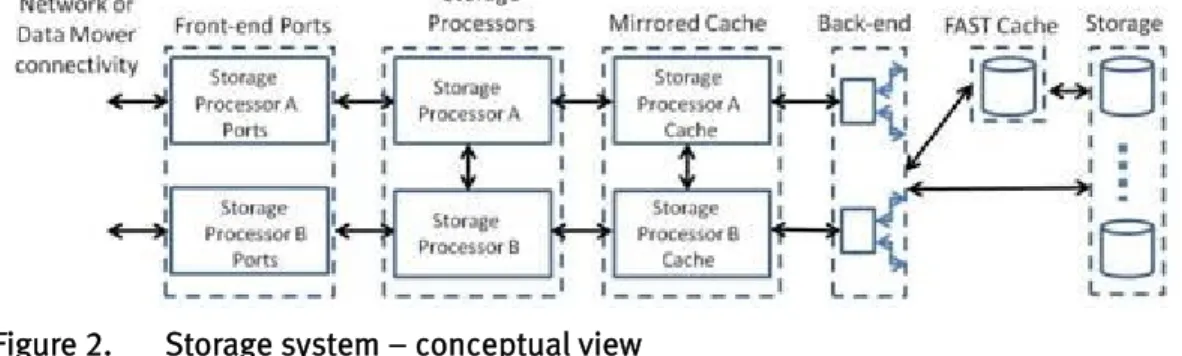
Figure 2 shows the relationship between the storage system’s major components.
Figure 2. Storage system – conceptual view
Balancing is best achieved at both the physical and logical levels. Physically, this requires installing or selecting storage devices in enclosures attached to separate back-end ports. At the logical level, this requires creating LUNs that distribute their I/O evenly across storage processors.
Note To achieve physical distribution you may need to physically relocate drives between disk-array processor enclosures (DPEs) and disk-array enclosures (DAEs). Ideally, this should be done when the storage system is first
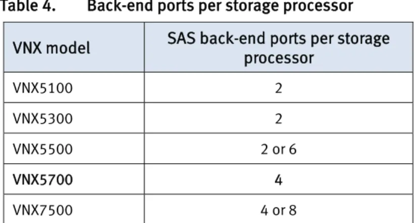
provisioned, or with drives and slots that are not in use. Be aware, drives that have already been provisioned into RAID groups or Virtual Provisioning™ pools cannot be removed or relocated without deleting the storage object. VNX models with more than two back-end SAS ports per storage processor (see Table 4) have a performance advantage when using specific ports, if all ports are not in use. When all ports are in use, there is no performance advantage in using one port over another.
• If you are using only two back-end buses on a VNX5700, you should use ports 0 and 2 or 1 and 3 for the best performance.
• If you are using four or fewer back-end ports on a VNX7500, you should alternate ports on the SAS back-end I/O module for the best performance.
Table 4. Back-end ports per storage processor
VNX model SAS back-end ports per storage processor
VNX5100 2 VNX5300 2
VNX5500 2 or 6
VNX5700 4
VNX7500 4 or 8
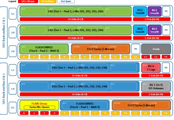
This solution was based on a VNX5700, and used ports 0 and 2, which were configured prior to any storage being configured on the array. Figure 3 shows the layout of the configuration. The VNX5700 storage allocation section contains more details.
Figure 3. Storage design and back-end port balancing for VNX5700 production array
Workload
balancing Best practice is to evenly distribute the workload for storage system resources across machines with common load types. As well as balancing workload across back-end ports, additional balancing can be achieved by:
• LUN ownership • LUN I/O
• Feature utilization
Balancing through LUN ownership
Balancing across storage processors is performed by LUN provisioning in anticipation of the workload’s requirements. It is the total I/O being handled by the assigned LUNs that is used in balancing, not the number of LUNs assigned to each storage processor. For example, fewer heavily utilized LUNs assigned to SP A may be balanced by a greater number of moderately utilized LUNs assigned to SP B. Balancing through LUN I/O
A component of balancing LUN I/O workload across storage processors is through the system’s front-end ports, largely performed by PowerPath in addition to a careful assignment of ports and zoning to hosts (refer to the EMC PowerPath/VE section for more information.) However, front-end ports are owned by storage processors. The number of active ports, and their utilization, directly affects storage processor utilization. In order to achieve a lower average host response time for the storage system, it is recommended to distribute the I/O between the two storage processors.
Balancing performance through EMC VNX feature utilization
For this solution, the following sub-set of VNX features was employed: • Multiple-pools
• FAST VP • FAST Cache Multiple pools
It is a recommended practice to segregate the storage system's pool-based LUNs into two or more pools when availability or performance may benefit from separation. The following considerations, which also apply to traditional LUN performance, should always be taken into account when implementing Virtual Provisioning pool-based storage:
• Drive contention: More than one LUN will be sharing the capacity of the drives making up a pool. When provisioning a pool, there is no manual control over data placement within a pool.
• Host contention: More than one host will likely be engaging each storage processor. Both storage processors have equal and independent access to a pool. Unless separate pools are created, there is no control over host access within the shared pool.
Note Pools are designed for ease-of-use. The pool dialog feature algorithmically implements many best practices.
Additionally, FAST Cache may not be required for all pool LUNs. Adopting a multiple pool strategy simplifies storage design, allowing FAST Cache to be enabled at pool level.
Note There are several strategies available for creating multiple pools. It is up to you to determine how many pools meet your storage goals and business priorities.
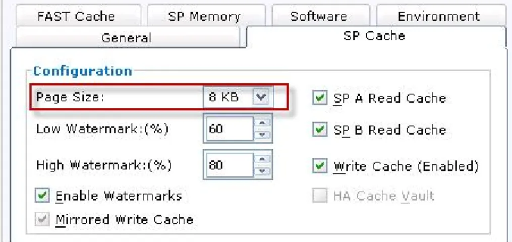
SP cache page size
An 8 KB page size is ideal in this OLTP-focused environment, as shown in Figure 4, where the storage system is supporting targeted search and manipulation of small block data. The data being requested from storage is typically 4 or 8 KB. The 8 KB cache page size provides the best performance for random I/O workloads with أ 8 KB I/Os.
Figure 4. Specify SP cache page size FAST VP
The ability of FAST VP to automatically relocate data between tiers at scheduled intervals provides the ability to adapt to changes in I/O patterns. Typically, OLTP data changes as old data “cools” and the new data being written to the database
potentially becomes the “hot data”.
With the ability of Flash drives to service far higher IOPS than SAS or NL-SAS drives (as shown in Table 5), you can service higher I/O with a smaller physical footprint and lower power usage.
FAST Cache
The potential increase in performance provided by FAST Cache is dependent on the workload and the configured cache capacity. Workloads with high locality of
reference, small block size, random read I/O, and high concurrency benefit the most. Workloads made up of sequential I/Os benefit the least.
OLTP workloads typically have a read/write ratio of approximately 80:20, with a small I/O size of 8 KB, providing an ideal profile for FAST Cache. Their hot data changes frequently. FAST Cache provides the ability to respond to this change in data I/O requirements. It will not promote data located within the Flash tier of a FAST VP pool, but will promote data residing in the lower tiers. This provides a fast reaction to changes in I/O that occur between scheduled FAST VP relocation windows.
FAST Cache is provisioned with Flash drives, which must be allocated in pairs to FAST Cache. Current EMC best practice is to keep the primary and secondary physical drives on the same bus.
This solution employs 12 Flash drives, which consist of six mirrored pairs. To distribute the FAST Cache across the buses, six drives were configured to use Bus 0 and six drives to use Bus 2. This placed three mirrored drive pairs across each bus, as shown in Figure 3.
Storage design
Sizing FAST VPpools and FAST Cache
The target load for both the standalone (SA) and WSFC configurations was 50,000 IOPS. For the SA SQL Server, the application had a host IOPS requirement of 25,000. The example below shows how this was calculated.
Utilization recommendation
As drive utilization increases, response time likewise increases, according to Little’s Law. At approximately 66 percent utilization, response times increase dramatically. It is not recommended to use the full rule-of-thumb IOPS for performance planning. A drive that has 180 IOPS (15k RPM SAS) will be at almost full utilization under that throughput. The response times of individual I/Os can be large. It is prudent to plan for approximately 2/3 of rule-of-thumb IOPS for normal use. This leaves more than enough margin for bursty behavior and degraded mode operation.
Performance estimate procedure
In this solution, these steps were followed to perform a rough order of magnitude (ROM) performance estimate:
1. Determine the workload. 2. Determine the I/O drive load.
3. Determine the number of drives required for performance. Determine workload
This is often one of the most difficult parts of the estimation. You may not know what the existing loads are, or the load for the proposed systems. Yet it is crucial for you to make a forecast as accurately as possible. An estimate must be made.
The estimate should include not only the total IOPS, but also what percentage of the load is reads and what percentage is writes. Additionally, the predominant I/O size must be determined.
Determine I/O drive load
In this solution, separate pools were used to service the data files from each Microsoft SQL instance. The default private RAID group is a RAID 5 pool (4+1) configuration. This gave a good balance of capacity and capability for the Flash tier. A disk configuration of 40 SAS 10k rpm drives with five Flash drives was chosen to create a heterogeneous pool totaling nine private RAID groups. The read/write ratio of the OLTP workload was 9:1, with the page size for Microsoft SQL Server being 8 KB. An application will have a host IOPS requirement, in this case 25,000, which typically
The calculation below requires the use of Table 5. Note the IOPS values in the table are drive IOPS.
Table 5. Small block random I/O performance by drive type
Drive type IOPS
Flash drive 3,500
SAS 15k rpm 180
SAS 10k rpm 150
NL-SAS 7.2k rpm 90
To determine the number of drive IOPS implied by a host I/O load, adjust as follows for parity or mirroring operations:
• Parity RAID 5: Drive IOPS = Host read IOPS + 4 x Host write IOPS • Parity RAID 6: Drive IOPS = Host read IOPS + 6 x Host write IOPS • Mirrored RAID 1/0: Drive IOPS = Host read IOPS + 2 x Host write IOPS Using the Parity RAID 5 calculation:
• Back-end disk IOPS = (0.9 x 25,000 + 4 x (0.1 x 25,000)) = 32,500 Figure 5 shows the back-end drive IOPS capability of this configuration.
Figure 5. Back-end drive IOPS capability
After working out the maximum drive IOPS for each tier, also factor in: • 66 percent for SAS drive, according to Little’s Law.
• For Flash drives, which do not adhere to Little's Law, the application of 66 percent relates more to what is the typical fill of hot data in that extreme tier. The reasoning applied is that FAST VP on VNX works on slices of 1 GB. Within those slices some of the data blocks may consist of luke-warm or colder data, which do not need to be serviced as regularly as in-demand hot data blocks.
Determine number of drives required for performance
Make a performance calculation to determine the number of drives in the storage system.
Divide the total IOPS (or bandwidth) by the per-drive IOPS value provided in Table 5 for small-block random I/O.
The result is the approximate number of drives needed to service the proposed I/O load. If performing random I/O with a predominant I/O size larger than 16 KB (up to 32 KB), but less than 64 KB, increase the drive count by 20 percent. Random I/O with a block size greater than 64 KB must address bandwidth limits as well. This is best done with the assistance of an EMC USPEED professional.
Storage
configuration The production storage configuration for the solution is shown in Table 6.
Table 6. Production array storage configuration
RAID type Pool/RAID group Disk configuration Purpose RAID 5 SAS and Flash
drives pool (Pool 1 ‐ Windows Failover Cluster virtual machines) 40 x 2.5” 600 GB 10k SAS 5 x 3.5” 100 GB Flash drives OLTP database 1 (WSFC) data files
RAID 5 SAS & EFD pool (Pool 2 ‐ Standalone SQL virtual machine) 40 x 2.5” 300 GB 10k SAS 5 x 3.5” 100 GB Flash drives
OLTP database 2 (SA) data files
RAID 5 SAS RAID group (RAID Group 0)
5 x 2.5” 600 GB 10k
SAS Virtual machine operating systems and page files RAID 5 SAS RAID group
(RAID Group 1)
4 x 3.5” 600 GB 15k
SAS OLTP SQL Server System (Master, Model, MSDB) and WSFC Quorum
RAID 1/0 SAS RAID group (RAID Group 4)
4 x 2.5” 600 GB 10k
VNX5700 storage
allocation Table 7 details the storage LUNs provisioned for the solution from the VNX5700 array.
Table 7. Storage LUNs
Name RAID Type Capacity User
(GB) Owner
Storage Pools/RAID
Groups Tiering Policy LUN_101 - OLTP Data Files (WSFC) RAID 5 750
SP A
Pool 1 - Windows Failover Cluster VMs (40 SAS & 5 EFD, RDM volumes)
Auto-Tier LUN_102 - OLTP Data Files (WSFC) RAID 5 750
LUN_103 - OLTP Data Files (WSFC) RAID 5 100 LUN_104 - OLTP Data Files (WSFC) RAID 5 100 LUN_201 - OLTP Data Files (SA) RAID 5 750
SP B Pool 2 - Standalone SQL VM (40 SAS & 5 EFD, VMFS-5 volumes) LUN_202 - OLTP Data Files (SA) RAID 5 750
LUN_203 - OLTP Data Files (SA) RAID 5 100 LUN_204 - OLTP Data Files (SA) RAID 5 100
RG0-OS Volumes RAID 5 1,024 SP B RAID Group 0
RG1-MSDTC RAID 5 5 SP A
RAID Group 1
RG1-WSFC QUORUM RAID 5 1 SP B
LUN_100 - System DB (WSFC) RAID 5 10 SP A
LUN_200 - System DB (SA) RAID 5 10 SP B
LUN_301 - TempDB (WSFC) RAID 1/0 100 SP A
RAID Group 2
LUN_302 - TempDB (SA) RAID 1/0 100 SP B
RG2_SDRS_DS1 (SDRS Test DS) RAID 1/0 250 SP A
LUN_303 - TempDB (WSFC) RAID 1/0 50 SP B
LUN_304 - TempDB (WSFC) RAID 1/0 100 SP A
RAID Group 3
RG3_SDRS_DS2 (SDRS Test DS) RAID 1/0 250 SP B
LUN_305 - TempDB (SA) RAID 1/0 100 SP A
LUN_306 - TempDB (SA) RAID 1/0 50 SP B
LUN_105 - MSSQL_tpce_log
(WSFC) RAID 1/0 200 SP B RAID Group 4
LUN_205 - MSSQL_tpce_log (SA) RAID 1/0 200 SP B
Table 7 shows that balancing across the storage processors was performed during LUN provisioning in anticipation of the workload’s requirements.
Note It is the total I/O being handled by the assigned LUNs that is used in balancing, not the number of LUNs assigned to each storage processor. Take note of the separation of Flash drives across Bus 0 and Bus 2 which separates Flash drives across physical ports on the VNX. Primary and secondary Flash Cache
physical drives are kept on the same bus. These are current EMC best practices for performance on the VNX storage series. Refer to the VNX Best Practice document, which is available on Powerlink.
EMC VSI
provisioning EMC VSI automates the task of provisioning storage. The EMC VSI is a client-side plug-in and is installed along with the VMware Infrastructure (VI) Client. Once VSI has been installed and enabled, a new icon is displayed in vSphere client under
Solutions and Applications. Some post-configuration tasks must then be completed. In the VNX section in vCenter, input the IP address of the SP A/B controllers together with the login credentials.
Provisioning new storage
On the Properties window of a VMware HA cluster, the EMC menu allows you to provision new storage; you can specify either a Disk/LUN or Network File System.
You can select the Disk/LUN option in the wizard, as shown in Figure 7. This allows you to select which VNX to use.
Figure 7. Select Disk/LUN
You can select the storage pool from which to carve the LUN. As shown in Figure 8, the storage pool called Pool 2 - Standalone SQL VM (40 SAS & 5 EFD) was selected, as this is the dedicated pool for the Microsoft SQL Server virtual machine named SQL-SA.
Figure 8. Select storage pool
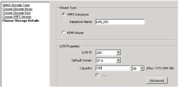
You can complete the whole process by choosing LUN number, size, and whether to format it as VMFS or leave it blank for an RDM, as shown in Figure 9.
Note VSI is also aware of EMC’s FAST VP Auto-Tiering policy features.
Figure 9. Format LUN
Once you click Finish, VSI handles the rest of the process. The VMFS volume name entered in the dialog box is also set as the “friendly” name of the LUN in Unisphere, as shown in Figure 10. The provisioning of storage within VSI can be configured on a per-user access policy.
VSI Storage Viewer
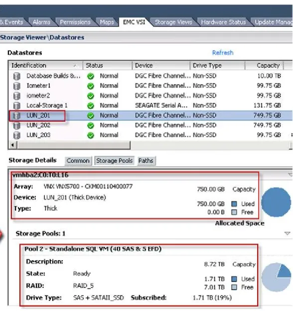
As shown in Figure 11, EMC Storage Viewer adds additional visibility to your storage from vCenter. By selecting the EMC VSI tab and selecting a data-store, you can view all the information for the volume. For example, you can select VMFS datastore LUN_201 to view all details of the VNX storage pool that LUN_201 resides on.
Figure 11. VSI Storage Viewer
SQL standalone and WSFC FAST VP pools
Both Fast VP pools were created with the same attributes. The pools were easy to create and required only these user inputs:
• Pool name
• Disks: number and type
• Protection level: RAID 5, 6, or 1/0
In this solution, RAID 5 protection level was used in both pools, which were initially created as homogeneous pools with 40 SAS drives. With 40 drives for a RAID 5 pool, Virtual Provisioning creates eight five-drive (4+1) RAID groups.
Note Use the general recommendations for RAID group provisioning for traditional LUNs when selecting the provisioning of the storage pool’s RAID types. Expanding a homogeneous pool to a heterogeneous pool for tiering
After completing baseline testing (refer to the Test results section), both pools were expanded with the addition of five 100 GB Flash drives on each. For RAID 5, initial drive allocation and expansion should be in multiples of five. Virtual Provisioning creates one five-drive (4+1) RAID group.
The procedure for expanding storage pool properties in Unisphere is as follows: 1. Select the Disks and click Expand.
2. Select the additional disks required.
As these changes are applied, a warning is displayed stating that adding the additional drive types will create multiple tiers. FAST VP automatically creates Tier 0 as the highest tier, with the Flash drives as the optimal performing drives. The SAS drives, which are already allocated, become Tier 1, which is the lowest tier.
After expanding the pools with different drive types, automatic data movement can now be performed on appropriate drive tiers depending on the I/O activity for the data. The Flash drives immediately become the pool’s highest tier, and the most frequently accessed data in the pool is now moved to this (extreme performance) tier. Once you enable auto-tiering on the LUNs, FAST VP technology continuously monitors and analyzes data workloads to generate the tiering recommendations to move colder (inactive) data to lower capacity optimized storage tiers and hotter (active) data to higher performing tiers.
Tiering is done at the sub-LUN level, through the use of 1 GB segments. This ability greatly reduces provisioning uncertainty, since data is moved according to the activity level and administrators are no longer locked into committing to a provisioning strategy that can quickly and unexpectedly change.
This ability to automatically locate data to the appropriate tier so that it is effectively located in the right place, at the right time, is a major breakthrough in storage technology. Through investment in Flash and FAST VP technology, workloads can be serviced through a smaller physical footprint on the array than traditional
configurations required. This provides the additional benefits of lower investment, lower running costs, and simplified administration, while maintaining or increasing workload performance.
Data relocation in FAST VP is governed by the global relocation setting on the Tiering tab of the Storage Pool Properties window. This presents you with two options, manual or scheduled, as shown in Figure 12.
Figure 12. Manual tiering selected
With the Manual option selected, data relocation on the selected storage pool is initiated, and you can select the rate and the duration for the data relocation to complete, as shown in Figure 13.
Data relocation can occur at three different rates: • High
• Medium
• Low
Figure 13. Data relocation options
You can start, pause, and stop the relocation at any stage of the process.
Table 8 details the available tiering policies.
Table 8. Tiering policies
Policy Description
Auto-Tiering
(recommended) Best for most users, adjusts the busiest data to the fastest tier. Highest Available Tier Sends the most critical data to the highest tier.
Lowest Available Tier Sends the least performance-sensitive data to the lowest tier.
No Data Movement Data is distributed evenly but is not moved after that. The tiering policies are set in the LUN Properties window, as shown in Figure 14.
Figure 14. Tiering policies After relocation
After relocation occurs and the hottest data is moved to the Flash tier, you can see that in both Microsoft SQL instances only LUNs 101 and 102 from Pool 1 and LUNs 201 and 202 from Pool 2 have a percentage of data moved to the Flash tier (Tier – Extreme Performance).
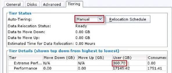
Figure 15 shows 360 GB of space on the Flash tier, with 324 GB consumed. FAST VP fills the available space on tiers to 90 percent when auto-tiering is the chosen tiering policy (10 percent is automatically reserved by the system).
Figure 15. Pool 1 after relocation
After the four-hour relocation window, LUN_102 properties were checked;
21.43 percent of the LUN was moved to the Flash tier in Pool 1, as shown in Figure 16.
Figure 16. Properties for LUN_102
After the four-hour relocation window, LUN_103 properties were checked. None of the LUNs were moved to the Flash drives in Pool 1, as shown in Figure 17.
Figure 17. Properties for LUN_103
Table 9 details the distribution of the LUNs in the FAST VP-enabled pools. The test databases used in both the WSFC and standalone Microsoft SQL instances are identical, and distribution across tiers for the four LUNs in each pool is almost
identical. A slight deviation is normal, as in a FAST VP-enabled pool, data is allocated to 1 GB slices, and the initial distribution of data to these slices during initial data load will vary.
Table 9. LUN distribution across tiers in FAST VP-enabled pools
Pool Pool 1: WSFC Pool 2: Standalone
LUN 101 102 103 104 201 202 203 204
Flash Tier
(percent) 20.39 21.43 0 0 20.21 22.03 0 0
SAS Tier
(percent) 79.61 78.57 100 100 79.79 77.97 100 100
FAST Cache FAST Cache uses a RAID 1 paired drive provisioning to provide both read and write
caching, in addition to mirrored data protection. All of the FAST Cache drives must be the same capacity.
Enabling FAST Cache
It is recommended that FAST Cache is installed during periods of low or no activity. Creating a FAST Cache disables the storage system’s read/write cache until the process is complete. As a result, the storage system’s write cache is flushed in order to zero and then be automatically reconfigured with less memory, (see Figure 18). While the read/write cache is disabled, overall performance can be adversely affected.
Figure 18. Disable SP cache
The time it takes to fully configure the FAST Cache depends on the cache’s size and any workload activity on the storage system. Larger FAST Caches take longer to configure. On a quiet system with low activity and small FAST Caches, the
configuration can take several minutes. Configuring a large FAST Cache on a loaded storage system may take longer than an hour. Figure 19 shows FAST Cache details.
Figure 19. Configuring FAST Cache
FAST Cache provides an effective way of increasing Virtual Provisioning pool performance.
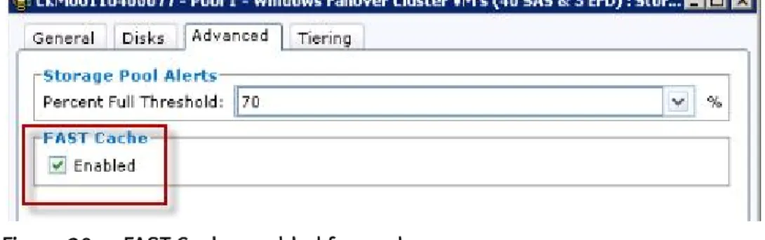
Multiple pools
FAST Cache is enabled at the pool level with Virtual Provisioning. Any number of pools may utilize FAST Cache at the same time. However, the entire pool, not individual LUNs, will have FAST Cache enabled or disabled.
Figure 20. FAST Cache enabled for pools Virtual Provisioning pools with Flash drives
With FAST VP-enabled virtual provisioned pools, data on the pool’s Flash drives is not cached by the FAST Cache feature.
VMware design
Overview When deploying Microsoft SQL Server 2008 R2 in a virtual environment, you need to
make several design decisions, such as specific database requirements in relation to CPU, memory, and storage, in order to maintain or improve database performance. In this white paper, EMC provides guidance to help you virtualize SQL Server using VMware vSphere 5.
Virtual machine
allocations EMC deployed SQL Server virtual machines with the configuration settings as shown in Table 10 and Table 11.
Table 10. Windows Failover Cluster virtual machine configurations
Name and Role vCPUs Memory Disks vSCSI Controller
SQL-WFC01/02: clustered instance of Microsoft SQL Server 2008 R2 24 vCPU (Number of virtual sockets: 3; Number of cores per socket: 8) 64 GB reserved (SQL max server memory 60 GB)
100 GB OS and Page File
(VMDK) 0:0 (LSI Logic SAS)
40 GB Program Files (VMDK) 0:1 (LSI Logic SAS) 1 GB QUORUM (RDM) 1:0 (LSI Logic SAS)
Physical
5 GB DTC (RDM) 1:1 (LSI Logic SAS) Physical
750 GB OLTP Data Files (RDM) 2:0 (LSI Logic SAS) Physical
750 GB OLTP Data Files (RDM) 2:1 (LSI Logic SAS) Physical
100 GB OLTP Data Files (RDM) 2:2 (LSI Logic SAS) Physical
100 GB OLTP Data Files (RDM) 2:3 (LSI Logic SAS) Physical
100 GB TempDB (RDM) 3:0 (LSI Logic SAS) Physical
100 GB TempDB (RDM) 3:1 (LSI Logic SAS) Physical
50 GB TempDB (RDM) 3:2 (LSI Logic SAS) Physical
200 GB SystemDB (RDM) 3:3 (LSI Logic SAS) Physical
10 GB Transaction Logs (RDM) 3:4 (LSI Logic SAS) Physical
Table 11. Standalone virtual machine configurations
Name and Role vCPUs Memory Disks vSCSI Controller
SQL-SA: standalone instance of Microsoft SQL Server 2008 R2 24 vCPU (Number of virtual sockets: 3; Number of cores per socket: 8) 64 GB reserved (SQL max server memory: 60 GB)
100 GB OS and Page File
(VMDK) 0:0 (Paravirtual)
40 GB Program Files (VMDK) 0:1 (Paravirtual) 75 GB SDRS Test DS (VMDK) 0:2 (Paravirtual) 745 GB OLTP Data Files
(VMDK) 1:0 (Paravirtual)
745 GB OLTP Data Files
(VMDK) 1:1 (Paravirtual)
98 GB OLTP Data Files (VMDK) 1:2 (Paravirtual) 98 GB OLTP Data Files (VMDK) 1:3 (Paravirtual) 95 GB TempDB (VMDK) 2:0 (Paravirtual) 95 GB TempDB (VMDK) 2:1 (Paravirtual) 47 GB TempDB (VMDK) 2:2 (Paravirtual) 8 GB SystemDB (VMDK) 2:3 (Paravirtual) 195 GB Transaction Logs (VMDK) 2:4 (Paravirtual) Microsoft SQL configuration for WSFC in VMware
A cluster of virtual machines across physical hosts (also known as a cluster across boxes (CAB)) protects against software failures and hardware failures on the physical machine by placing the cluster nodes on separate ESXi hosts. The virtual machines share a private network connection for the private Heartbeat and a public network connection, as shown in Figure 21. A dvswitch with Heartbeat network was created as a dvportgroup.
As shown in Figure 22, a second vNIC adapter was added in the Virtual Machine Properties to carry the cluster communications traffic (virtual machines configured as cluster nodes must use vmxnet network adapters). The vNIC was connected to the heartbeat port group.
Figure 22. Second adapter added
After the network configuration was completed, virtual disks were added to the virtual machine for the cluster. This is detailed in the VMware Setup for Microsoft Cluster Service guide available on the VMware website.
Storage array LUNs were mapped as RDMs to the primary virtual machine. You need to set up a separate vSCSI controller for clustered disks, as clustered disks cannot reside on the same vSCSI controller as the operating system boot drive. You also should map your database and log LUNs on separate vSCSI adapters, as shown in Table 10, keeping similar workloads on vSCSI adapters.
Note In a vSphere HA cluster, WSFC is not supported for DRS and vMotion. Only a two-node WSFC cluster is allowed.
You have the option of storing the mapping file with the virtual machine or on a datastore that has common access to all nodes in the VMware datacenter. EMC chose to store the mapping file on common storage in a location created by the first virtual machine that maps the storage. In this case, it is the RG0-OS Volumes datastore in the SQL-WFC01 folder, as shown in Figure 23.
Figure 23. Mapping file location
The RDM LUNs have to be in physical compatibility (pass-through) mode in order to allow the virtual machine to directly access the presented LUNs; however, using this mode does not allow the creation of VMware snapshots. There are two changes which you need to make to the vSCSI adapter. Physical mode is enabled, and the SCSI Controller Type is changed to the “SAS adapter”, as Windows Server 2008 no longer supports SCSI-2 reservations, see Figure 24. The LSI Logic SAS adapter supports SCSI-3 reservations.
As shown in Figure 25, vSCSI adapter 0 is not in SCSI Bus Sharing mode. This is because the adapter holds the operating system boot and program files drive, which do not need to be in SCSI Bus Sharing mode, and there is no need to share it with other virtual machines. Being in SCSI Bus Sharing mode could possibly result in data corruption as well as an unsupported Microsoft operating system configuration.
Figure 25. vSCSI adapter 0 not in SCSI Bus Sharing mode
Settings on the second cluster node are edited to map the LUNs already created on SQL-WFC01. Each disk is given the same SCSI address in both virtual machines (WFC01 and WFC02.)
Memory is not overcommitted. The Memory Reservation (minimum memory) option is set to be the same as the virtual machine, as shown in Figure 26.
Figure 26. Memory reservation
For WSFC CAB, virtual machines in a cluster must be configured for DRS anti-affinity rules. Virtual-machine-to-virtual-machine anti-affinity rules are created, as shown in Figure 27. Strict enforcement of this rule is also enabled.
Figure 27. Anti-affinity rules
Figure 28. DRS Advanced Options window
EMC used virtual-machine-to-host affinity rules because vSphere HA does not obey virtual-machine-to-virtual-machine affinity rules. Otherwise, if a host fails, vSphere HA could put clustered virtual machines, which are meant to stay apart, on the same host. This problem is avoided by setting up DRS groups and using virtual-machine-to-host affinity rules, shown in Figure 29, which are obeyed by vSphere HA.
Figure 29. Host affinity rule
When finished with the secondary node storage configuration, Microsoft .NET application server roles are installed, associated role services configured, and the failover cluster feature added to both primary and secondary virtual machines in the cluster.
• On the primary node, Disk Manager is opened, all newly presented disks are brought online and, using DiskPart, the disks are aligned to prevent split I/Os. • On the secondary virtual machine, disk letters are mapped exactly as they are
mapped on the primary virtual machine. Using the Microsoft Cluster validation wizard, the cluster configuration is validated.
• After completion of the validation, EMC uses Microsoft Failover Cluster Management options to create a Windows Server failover cluster to support a clustered SQL Server 2008 instance.
• The Failover Cluster Management tools are then used to configure the Cluster Quorum drive and settings to specify failover conditions for the cluster. • With the cluster fully configured and functional, the Microsoft Distributed
Transaction Coordinator (MSDTC) is configured.
Note SQL Server uses the MSDTC for distributed queries, replication, and two-phase commit transactions.
• The last step is to install SQL Server 2008 on the failover cluster primary and secondary nodes.
Microsoft SQL configuration for standalone HA virtual machine in VMware
VMware vSphere High Availability (HA) is a major factor in providing availability to business-critical applications such as Microsoft SQL Server. HA is an excellent solution in providing availability for any application running within a virtual machine in VMware. HA allows the creation of a cluster of ESXi servers, which enables the protection of virtual machines and therefore the applications that run on them. In the event of a failure of one of the hosts in the cluster, impacted virtual machines are automatically restarted on other ESXi hosts within the same cluster.
In vSphere 5, HA has been redesigned and functionality has been added. Some of the changes include:
• No dependency on DNS: vSphere HA no longer has any dependency on DNS resolution by each host in the cluster. Eliminating this reduces the likelihood that an outage of an external component will have an effect on the operation of vSphere HA.
• Primary/secondary nodes: the concept of primary and secondary nodes has been completely removed. The new model incorporates a master-slave relationship between the nodes in a cluster, where one node is elected to be a master and the rest are slaves. The master node coordinates all availability actions with the other nodes and is responsible for communicating that state to the vCenter server. The agent that plays the master is called Fault Domain Manager (FDM). (Automated Availability Manager (AAM) is the vSphere 4.1 agent.)
• Datastore heartbeating: Another enhancement is the ability to enable communication between the nodes within a cluster through the storage subsystem. vSphere HA utilizes multiple paths of communication through the network and storage. Not only does this allow for a greater level of
redundancy, but it also enables better identification of the health of a node and the virtual machines running on it.
VMware HA enables you to recover from host outages by restarting your SQL Server virtual machine on other surviving nodes in a VMware HA/DRS cluster. Crash consistency of the virtual machines is ensured during a host outage. Using VMware HA in combination with VMware DRS facilitates automatic restart of virtual machines as well as intelligent load balancing of the entire VMware HA/DRS cluster. (HA/DRS is not available to the WSFC cluster virtual machines.)
SQL-SA virtual machine configuration
For the standalone SQL Server virtual machine, a fully-virtualized configuration is used; it consists of VMFS-5 volumes with dedicated single Virtual Machine Disk
The VMDK files were formatted as Thick Provision Eager Zeroed (eagerzeroedthick), specifically for database and log files, as shown in Figure 30. An eager-zeroed thick disk has all space allocated and zeroed out at the time of creation. This increases the time it takes to create the disk, but results in the best performance, even on the first write to each block.
Note By using a VAAI-capable SAN storage array (VNX5700), eager-zeroed thick disk creation is quicker as it offloads zeroing operations to the storage array. (VAAI is vStorage APIs for Array Integration.)
Figure 30. Formatted VMDK files
Multiple VMware Paravirtual SCSI (PVSCSI) adapters and evenly distributed target devices are used, as shown in Table 11.
Multi-NIC vMotion configuration
An enhancement with vSphere 5 is the ability to use multiple NICs in a vMotion configuration to assist with transferring memory between hosts. Enabling multiple NICs for vMotion-enabled VMkernels removes some of the constraints (from a
bandwidth/throughput perspective) that are associated with large memory active SQL virtual machines. The results are documented in the Validation section.
To configure for multi-NIC vMotion, each VMkernel Interface (vmknic) is bound to a physical NIC (using four NICs). These steps were followed:
1. Created a VMkernel interface and named it vMotion01.
2. Edited settings of this port group and configured one physical NIC-port as active and all others as standby, shown in Figure 31.
3. Created a second VMkernel interface and named it vMotion02.
4. Edited the settings of this port group and configured a different NIC port as active and all others as standby.
5. Followed steps 1 to 4 for each VMkernel interface.
Figure 31. Configure NICs
This configuration was applied to both hosts in the HA/DRS cluster, as shown in Figure 32. This is for a four-NIC vMotion configuration.
A vMotion transition is initiated with this multi-NIC four-port configuration. When you use vMotion for just one virtual machine, all four of the links are fully utilized.
Running this with load against the SQL-SA virtual machine, EMC observed that there was a time when the virtual machine being moved was inaccessible on either the source host or the target host. This was for a short period of time, approximately 3 seconds. This was tested with a continuous ping (ping –t) on the SQL-SA virtual machine. The network is determining the location of the MAC address, and during this time packets are not received. Most client-server applications are built to withstand the loss of some packets before the client is notified of a problem.
Virtual Machine
Failure Monitoring This feature allows the host to communicate with the VMtools instance running inside the guest operating system. Similar to how the WSFC cluster heartbeat works, if no response is received from the VMtools instance, an assumption is made that the operating system has crashed, or is otherwise unavailable, and will be restarted, as shown in Figure 33.
Figure 33. Virtual machine monitoring
Virtual NUMA The SQL-SA and WSFC-01 virtual machines were configured with 24 vCPUs each,
following EMC best practices for virtual non-uniform memory access (vNUMA), as shown in Table 10.
Virtual NUMA, a feature in vSphere 5, exposes NUMA topology to the guest operating system, allowing NUMA-aware guest operating systems and applications to make the most efficient use of the underlying hardware’s NUMA architecture. The virtual
machines are sized so that they align with physical NUMA boundaries. For example, if you have a host system with eight cores per NUMA node (which was the case in our environment using Intel Xeon X7560 processors), you should size your virtual machines in multiples of eight vCPUs (that is, 8 vCPUs, 16 vCPUs, 24 vCPUs, and so on).
When creating a virtual machine, you have the option to specify the number of virtual sockets and the number of cores per virtual socket, as shown in Figure 34. If the number of cores per virtual socket on a vNUMA-enabled virtual machine is set to any value other than the default of 1, and that value does not align with the underlying physical host topology, performance might be slightly reduced. Therefore, if a virtual machine is to be configured with a non-default number of cores per virtual socket, for
best performance that number should be an integer multiple or integer divisor of the physical NUMA node size. By default, vNUMA is enabled only for virtual machines with more than eight vCPUs.
Figure 34. Virtual socket properties
You can obtain the maximum performance benefits from vNUMA if your clusters are composed entirely of hosts with matching NUMA architectures (in this solution, the two-node ESXi cluster consists of two servers with matching specifications). This is because the very first time a vNUMA-enabled virtual machine is powered on, its vNUMA topology is set, based in part on the NUMA topology of the underlying physical host on which it is running.
Once a virtual machine’s vNUMA topology is initialized it does not change unless the number of vCPUs in that virtual machine is changed. This means that if a vNUMA virtual machine is moved to a host with a different NUMA topology, the virtual machine’s vNUMA topology may no longer be optimal for the underlying physical NUMA topology, which potentially results in reduced performance.
VMware PVSCSI and LSI Logic SAS adapters
Compared to the LSI Logic SAS virtual SCSI adapter, the PVSCSI adapter shows an improvement in performance for virtual disks as well as improvements in the number of IOPS delivered. PVSCSI greatly improves the CPU efficiency and also improves the throughput when the workload drives very high I/O rates.
vSphere 5 Storage DRS I/O and capacity
Storage DRS can perform automated balancing of storage. Storage DRS allows the aggregation of multiple datastores into a single object called a datastore cluster. Storage DRS makes recommendations to balance virtual machines or disks based on I/O and space utilization. During virtual machine or virtual disk provisioning, it makes recommendations for placement. Storage DRS can be set in fully automated or
For this solution’s test configuration, two datastores are created on RAID Groups 2 and 3, named RG2_SDRS_DS1and RG2_SDRD_DS2. These datastores are provisioned through EMC VSI, as for all volumes in the configuration. Figure 35 shows the creation of the test datastore cluster.
Figure 35. Creating a new datastore cluster
After Storage DRS is activated, space load balancing and I/O load balancing functions are enabled within the datastore cluster named SDRS Test Cluster. The default
automation level is Manual Mode (shown in Figure 36), which means that Storage DRS will generate recommendations for placement and migrations. Manual Mode was used for testing.
Figure 36. Manual mode set for cluster
The default Storage DRS thresholds are used, as shown in Figure 37. The first
threshold defines the maximum acceptable utilized space of the VMFS datastore. The I/O latency threshold defines when Storage DRS recommends load balancing to reduce latency.
Figure 37. Thresholds set
The datastores to use in the cluster are selected, as shown in Figure 38.
The Ready to Complete screen (Figure 39) provides an overview of all the settings configured.
Figure 39. Datastore cluster options
Note Storage DRS has the ability to control VMDK locations on specific datastores. Intra-virtual machine VMDK affinity/anti-affinity rules can be created to
modify the behavior of Storage DRS. These ensure that the VMDKs that belong to a virtual machine are stored together on the same datastore, which is the intra-virtual machine affinity rule. The intra-virtual machine VMDK anti-affinity rule keeps the specified VMDKs, which belong to a virtual machine, on separate datastores.
Validation
Test objectives The testing of this solution validated the ability of the VNX5700 storage array to support multiple Microsoft SQL Server instances running OLTP-like workloads that generated over 50,000 IOPS in total. Tests involved:
• Introducing Flash drives to the storage array and utilizing them with FAST VP and FAST Cache to boost performance.
• Comparing both WSFC and standalone VMware Microsoft SQL Server instances during both planned and unplanned failovers. Test workloads for WSFC and standalone VMware Microsoft SQL Server instances were run in parallel.
• Demonstrating the functionality of vSphere 5 features, such as multi-NIC vMotion, hot add CPU, and Storage DRS.
Notes
Benchmark results are highly dependent on workload, specific application
requirements, and system design and implementation. Relative system performance will vary as a result of these and other factors. Therefore, this workload should not be used as a substitute for a specific customer application benchmark when critical capacity planning and/or product evaluation decisions are contemplated.
All performance data contained in this report was obtained in a rigorously controlled environment. Results obtained in other operating environments may vary.
Testing
methodology The testing methodology required TPC-E-like (OLTP) workloads to be run against two target databases, one instance running on a Windows Server Failover Cluster and one on a VMware standalone instance.
Note The ability of real-world applications to handle loss of connection will vary, based on design. The tool used in testing to generate workload had a specific behavior, which may not be indicative of customer environments.
Test scenarios EMC used a number of scenarios to test the solution. These included: • Baseline testing on an SAS-only pool
• Performance testing on a FAST VP-enabled pool (Flash and SAS) • Performance testing on a FAST VP pool with FAST Cache enabled
Performance test
procedures Testing was conducted by running concurrent TPC-E-like (OLTP) workloads against the target databases on the WSFC and standalone SQL Server instances. 1. Each SQL Server instance had its own RAID 5 storage pools for data files with
transactional logs running on traditional RAID 1/0 RAID groups. 2. A steady state was reached and a baseline performance measurement
observed, after which Flash drives were introduced to the pool and FAST VP enabled.
3. Workload continued to be applied, allowing hourly polling cycles to occur and relocation recommendations to be generated.
4. A FAST VP data relocation window was manually run and performance monitored throughout.
5. FAST Cache was enabled with load running and the performance again monitored with a peak performance level being reached.
Note The workload profiles parameters were not changed during testing. A profile was set to push the utilization of the SAS-only pools and show the impact on performance with the introduction of Flash drive tiers and the enabling of FAST VP.
This approach mimics the potential performance impact of enabling FAST VP and FAST Cache on busy OLTP production environments.
Metrics were taken using a combination of Microsoft SQL performance counters, EMC Unisphere NAR files, and VMware esxtop output.
Test results Testing was broken down into the following areas:
• Throughput • Failover
• VMware vSphere 5 functionality
Throughput testing The following are the key metrics:
• Throughput in IOPS (transfers/sec) • Throughput in transactions per sec (TPS) • Physical disk utilization (percent) • Storage processor utilization (percent)
Throughput in IOPS (transfers/sec)
Throughput was measured using the Microsoft Performance Monitor (perfmon) counter: LogicalDisk – Avg. Disk Transfer/sec.
Figure 40. Avg. Disk Transfer/sec (IOPS) for baseline, FAST VP, and FAST Cache During baseline testing with 40 SAS disks in each pool, the WSFC pool produced 6,500+ IOPS and the standalone instance produced 7,800+ IOPS.
After the introduction of five Flash drives to each of the two pools and a four-hour relocation window run, the WSFC IOPS rose to 12,625 and the standalone to 16,247. After enabling FAST Cache on the two pools, WSFC IOPS rose to 22,062 and the standalone IOPS to 29,409. The test showed more than a three times improvement in the ability to service I/O from a total baseline of 14,435 IOPS to an I/O peak of 51,471 with FAST Suite enabled.
Table 12. Throughput in IOPS (transfers/sec)
Stage WSFC pool (IOPS) instance (IOPS) Standalone Baseline testing with 40 SAS disks 6,500+ 7,800+ After adding five Flash drives and a
four-hour relocation window run 12,625 16,247
Throughput in transactions per sec (TPS)
Throughput was also measured using the Microsoft Performance Monitor (perfmon) counter: Databases – Disk Transactions/sec.
Figure 41. Disk transactions per sec (TPS) for baseline, FAST VP and FAST Cache During baseline testing with 40 SAS disks in each pool, the WSFC pool produced 940+ TPS and the standalone instance produced 1,150+ TPS.
After the introduction of five Flash drives to each of the two pools and a four-hour relocation window run, the WSFC TPS rose to 1,871 and the standalone to 2,434. After enabling FAST Cache on the two pools, WSFC rose to 3,293 TPS and the standalone to 4,484 TPS. This counter also shows more than a three times
improvement in the ability to service TPS from a total baseline of 2,402 TPS to a peak TPS of 7,777 with FAST Suite enabled.
Table 13. Throughput in transactions per sec (TPS)
Stage WSFC pool (TPS) instance (TPS) Standalone Baseline testing with 40 SAS disks 940+ 1,150+ After adding five Flash drives and a
four-hour relocation window run 1,871 2,434
After enabling FAST Cache 3,293 4,484
Results similarly showed a significant improvement in the TPS that the pools were able to service, after introducing Flash drives to the pools and enabling FAST VP; further dramatic improvements were seen after FAST Cache was enabled on both pools.