Deepwater Taranaki Basin
Single Exploration Well
Environmental Impact Assessment
New Zealand Block Petroleum
Exploration Permit 38451
Anadarko NZ Taranaki Company September, 2013
Anadarko NZ Taranaki Company
Deepwater Taranaki Basin
Single Exploration Well
Environmental Impact
Assessment
New Zealand Block Petroleum
Exploration Permit 38451
September, 2013
Prepared by:
Environmental Resources Management
www.erm.com
TABLE OF CONTENTS
1.0 INTRODUCTION 1
1.1 BACKGROUND 1
1.2 OBJECTIVES AND GENERAL APPROACH 3
1.3 LOCATION AND TIMING 7
1.4 CONSULTED SOURCES OF INFORMATION 7
1.5 CONSULTATION 8
1.6 LIMITATIONS 10
2.0 POLICY, LEGAL, AND ADMINISTRATIVE FRAMEWORK 11
2.1 NATIONAL LEGISLATION 11
2.2 INTERNATIONAL CONVENTIONS, TREATIES, AGREEMENTS, AND PROGRAMS 12
3.0 PROJECT DESCRIPTION 14
3.1 EXPLORATION DRILLING METHOD 14
3.2 EXPLORATION DRILLING ELEMENTS 14
3.2.1 Drilling Vessel Options 15
3.2.2 Drilling Vessel Storage Capacities 18
3.2.3 Part 200 Pre- and Post-Drilling Environmental
Monitoring 18
3.2.4 Drilling Vessel Mobilization 18
3.2.5 Typical Drilling Technique 19
3.2.6 Well Installation 19
3.2.7 Formation Evaluation 26
3.2.8 Demobilization 27
3.2.9 Drilling Support Operations 28
3.3 SAFETY PRECAUTIONS 29
3.3.1 Drilling Vessel Safety 29
3.3.2 Drilling Operation Emergency Response and Oil Spill Prevention 30
4.0 THE EXISTING ENVIRONMENT 32
4.1 PHYSICAL ENVIRONMENT 32
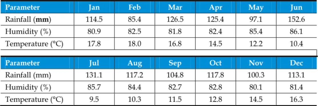
4.1.1 Climate 32
4.2.3 Marine Mammals 47
4.2.4 Marine Reptiles 57
4.2.5 Seabirds 57
4.2.6 Protected Natural Areas in the Vicinity of the Project Area 59 4.2.7 Sensitive Areas and Coastal Information 61
4.3 EXISTING INTERESTS 68
4.3.1 General Demographics 68
4.3.2 Maritime Traffic, Ports and Harbors 70
4.3.3 Fishing 71
4.3.4 Oil and Gas Activity 72
4.3.5 Other Uses 73
4.3.6 Cultural Environment 73
5.0 ENVIRONMENTAL IMPACT ASSESSMENT 76
5.1 METHODOLOGY 76
5.1.1 Assessment Methodology Stage I: Identification of
Potential Impacts and Scoping 76
5.1.2 Assessment Methodology Stage II: Developing
Mitigation Measures 78
5.1.3 Assessment Methodology Stage III: Evaluating
Residual Impacts 78
5.1.4 Assessment Methodology Stage IV: Re-evaluating
Significant Residual Impacts 83
5.1.5 Evaluation Criteria for Accidental or Unplanned Events 83 5.1.6 Assessment Methodology Stage IV: Re-evaluating
Significant Residual Impacts 84
5.1.7 Dealing with Uncertainty in the Assessment of Impacts 84
6.0 SOURCES OF IMPACTS FOR EXPLORATION WELL DRILLING 85
6.1 INTRODUCTION 85
6.2 IMPACT ASSESSMENT SCOPE 85
6.3 ASSESSMENT OF IMPACTS ON THE ENVIRONMENT FROM ROUTINE ACTIVITIES 88 6.3.1 Physical Presence of the Drilling Vessel and Support
Vessel 88 6.3.2 Operational Activities Associated with Exploration
Drilling 92 6.3.3 Solid and Liquid Wastes Generated on the Vessels 95
6.3.4 Decommissioning Activities 105
6.4 ASSESSMENT OF IMPACTS ON EXISTING INTERESTS FROM
ROUTINE ACTIVITIES 107 6.5 ASSESSMENT OF IMPACTS FROM ACCIDENTAL EVENTS 112 6.5.1 Accidental Introduction of Invasive Marine Species 113 6.5.2 Accidental Discharge of Trash and Debris 114
6.5.3 Vessel Collision or Sinking 115
6.5.4 Unplanned Discharges from Vessels 116
6.5.5 Loss of Well Control 117
6.5.6 Impacts of Natural Disasters 123
7.0 SUMMARY OF ENVIRONMENTAL IMPACTS 124
7.1 CUMULATIVE IMPACTS 124
8.0 ENVIRONMENTAL MANAGEMENT PLAN 131
8.1 INTRODUCTION 131
8.2 IMPLEMENTATION 131
8.3 ENVIRONMENTAL MANAGEMENT PLAN (EMP) 132
8.3.1 Actions for Commercial Fishing and Shipping
Lanes 133 8.3.2 Actions for Controlling Marine Pests 133 8.3.3 Actions for Mammals and other Marine Fauna 133
8.3.4 Actions for Marine Water Quality 134
8.3.5 Actions for Atmospheric Emissions 135
8.3.6 Actions for Accidental Events 135
9.0 CONCLUSION 139
10.0 REFERENCES 140
APPENDICES
A Stakeholder Engagement Register
B Discharge Management Plan Submitted to Maritime New Zealand for Approval (minus Annexes)
C Project Specific Exploration/Appraisal Drilling Information (Drilling Vessel/Project Data)
LIST OF TABLES
Table 1.1: The Project Area Details 3
Table 1.2: Compliance with Section 39 of the EEZ Act 4 Table 1.3: Guidelines and Protocols Referenced 5 Table 3.1: Main Characteristics of an Exploration Well and a Production Well 14 Table 3.2: Specifications of the Noble Bob Douglas 17 Table 3.3: Storage Capacity of the Noble Bob Douglas 18 Table 3.4: Romney Drilling Fluid Program and Projected Discharges 24 Table 4.1: Mean Monthly Weather Parameters at New Plymouth, Indicative for the
Project Area 32
Table 4.2: Total Catch (tonnes) of Top Five Species Caught in the Vicinity of the
Project Area 44
Table 4.3: Marine Mammals Potentially Present in the Project Area 47 Table 4.4: Species Listed On the NZ Threat Classification List 55 Table 4.5: Sensitive Sites and Coastal Environments Detailed in Regional MOSCPs
61 Table 5.1: The criteria for assessing the magnitude of impacts on the seabed,
seawater quality, ecological and social receptors 80 Table 5.2: The criteria for assessing the sensitivity of the seabed, seawater quality,
ecological and social resources and/or receptors 81 Table 5.3: Overall Significance Criteria for Impacts in the EIA 82 Table 5.4: Likelihood Categories for Unplanned Events 83 Table 5.5: Severity Criteria for Unplanned Events 83 Table 5.6: Unplanned Event Impact Significance Criteria 84 Table 6.1: Environmental Impacts from Project Drilling Activities Considered to be
of Unlikely Significance 85
Table 6.2: Environmental Impacts from Project Drilling Activities Considered to be
of Likely Significance 86
Table 6.3: Likely Presence of Species Listed on the NZ Threat Classification List within the Project Area at the time of the Exploration Well Drilling 89 Table 6.4: Estimated Amounts of Sanitary, Domestic Wastewater and BOD per day
for Exploration Drilling Activities 99 Table 6.5: Estimated Waste Streams and Typical Generation Quantities 104 Table 6.6: Total Air Emission Estimates for the Project Area Exploration Drilling
(tons per individual exploration well) 106 Table 7.1: Exploration Drilling Activity and Associated Impacts 125 Table 8.1: Environmental Management Plan 137
LIST OF FIGURES
Figure 1.1: Location of the Project Area (PEP 38451) and Surrounding PEP Blocks 2 Figure 1.2: Proposed Drilling Location within the Project Area 9 Figure 3.1: The Noble Bob Douglas, a Sixth Generation Dynamically Positioned
Drillship 17
Figure 3.2: Drilling Technique 22
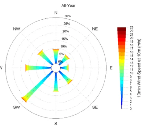
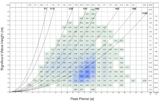
Figure 3.3: Diagram of a Typical Shale Shaker 23 Figure 3.4: Illustration of Subsea Blowout Preventer Stack 26 Figure 4.1: Project Area Annual Wind Rose 33 Figure 4.2: Taranaki Basin Map and Bathymetry 34 Figure 4.3: Percentage Occurrence of Significant Wave Height and Peak Period – All Year 35 Figure 4.4: Percentage Occurrence of Significant Wave Height and Direction – All
Year 35
Figure 4.5: New Zealand Currents 36
Figure 4.6: Joint Frequency Distributions of Current Speed and Direction at 0m –
All Year 37
Figure 4.7: Joint Frequency Distributions of Current Speed and Direction at 75m–
All Year 38
Figure 4.8: Joint Frequency Distributions of Current Speed and Direction at 750m–
All Year 38
Figure 4.9: Joint Frequency Distributions of Current Speed and Direction at 1500m–
All Year 39
Figure 4.10: Total Commercial Trawling Activity along the West Coast of the North Island 44 Figure 4.11: Whale Distribution in NZ Waters 48 Figure 4.12: Distribution of the Maui's Dolphin. 53 Figure 4.13: Locations of Protected Natural Areas in the Vicinity of the Project Area60 Figure 4.14: IMO Approved Precautionary Area 71
Figure 4.15: Taranaki Iwi Boundaries 74
Figure 6.1: Maximum Drill Cuttings Deposition Thickness: Scenario 1 (November) 97 Figure 6.2: Oil Spill Trajectory Modeling (Summer) 118
LIST OF ABBREVIATIONS
Abbreviation Definition
°C degrees Celsius
AIS Automatic Information System
ALARP As low as reasonably practicable Anadarko Anadarko NZ Taranaki Company bbls barrels
BOD Biochemical oxygen demand
BOEMRE Bureau of Ocean Energy Management, Regulation and Enforcement (US)
BOP Blow-Out Preventer
BPA Benthic Protection Area
cm centimeters
COLREGS International Regulations for the Prevention of Collisions at Sea
dB decibels
dB re 1µPa@1m decibels referenced to one micro-Pascal at one meter DoC Department of Conservation (NZ)
DMP Discharge Management Plan
EEZ Exclusive Economic Zone
EEZ Act Exclusive Economic Zone and Continental Shelf (Environment Effects) Act 2012 (NZ)
EHS Environment, Health and Safety
EIA Environmental Impact Assessment
EMP Environmental Management Plan
EPA Environmental Protection Authority ERM Environmental Resources Management ERP Emergency Response Plan
ha hectares Hz Hertz
IMO International Maritime Organization
IUCN International Union for the Conservation of Nature and Natural Resources
IWC International Whaling Commission kg kilograms
kHz kiloHertz km kilometer
km2 square kilometers
l liters
l/day liters per day
l/pers/day liters per person per day m meters
m3 cubic meters
mm millimeters
m/s meters per second
Abbreviation Definition
MARPOL International Convention for the Prevention of Pollution from Ships, 1973 as modified by the Protocol of 1978
MfE Ministry for the Environment (NZ) MOSCP Marine Oil Spill Contingency Plan MPI Ministry for Primary Industries
MSS Marine Seismic Survey
NABF Non-Aqueous Based Drilling Fluid
NABIS National Aquatic Biodiversity Information System (NZ) NIWA National Institute of Water and Atmospheric Research Ltd
(NZ)
Nm nautical miles
NZ New Zealand
NZ$ New Zealand Dollars
P2E Pathway to Excellence Management System
Part 200 Marine Protection Rules Part 200: Offshore Installations – Discharges
PEP Petroleum Exploration Permit
ppm Parts per million
QMS Quota Management System
RMA Resource Management Act 1991 (NZ)
rms Root mean squared
ROV Remotely Operated Vehicle
SOPEP Ship Oil Pollution Emergency Plan
Statistics NZ Statistics New Zealand (national statistical office) UNCLOS United Nations Convention on the Law of the Sea WBF Water Based Drilling Fluids
1.0 INTRODUCTION
1.1 BACKGROUND
This Environmental Impact Assessment (EIA) has been prepared for Anadarko NZ Taranaki Company (Anadarko) by Environmental Resources Management (ERM), a recognized independent international environmental consulting company.
Anadarko plans to undertake an oil and gas exploration/appraisal program located within the area of New Zealand (NZ) Petroleum Exploration Permit (PEP) Block 38451 of the Deepwater Taranaki Basin, also known as the Outer Taranaki Basin, off the west coast of the North Island of NZ (hereafter “the Project Area”). This EIA is to provide specific information for the current drilling campaign which consists of the drilling of a single exploration well. The EIA scope is to: Present the current understanding of the key environmental sensitivities and
existing interests related to the drilling of a single exploration well within the Project Area;
Assess the potential environmental impacts to the surrounding environment and existing interests as a result of drilling activity; and
Present measures that will be implemented to avoid or minimize adverse impacts to the surrounding environment and existing interests.
The drilling of a single exploration well is the first activity planned as part of Anadarko’s exploration/appraisal program, and is scheduled to be undertaken in the summer/autumn 2013-2014 drilling season (between November 2013 and February 2014). It is estimated that the drilling activity will take approximately 65 – 75 days.
Future exploration/appraisal drilling will be scheduled based on the results of the current one-well campaign. Details of future exploration/appraisal well drilling that may be undertaken, along with specific assessments of impact, will be submitted to EPA as separate applications under the Exclusive Economic Zone and Continental Shelf (Environment Effects) Act 2012 (EEZ Act) once details of the exploration/appraisal drilling are known. These activity-specific assessments will be provided to EPA as updates to this impact assessment and annexes. Information submitted will include well locations, spill trajectory maps, drilling vessel information and an updated Environmental Management Plan (EMP), if changes to the EMP are required.
The Project Area is owned by a joint venture comprising Anadarko (54%), Hyundai Hysco Co. Ltd (36%), Global Resource Holdings LLP (5%) and Randall C. Thompson LLC (5%), with Anadarko being the operator.
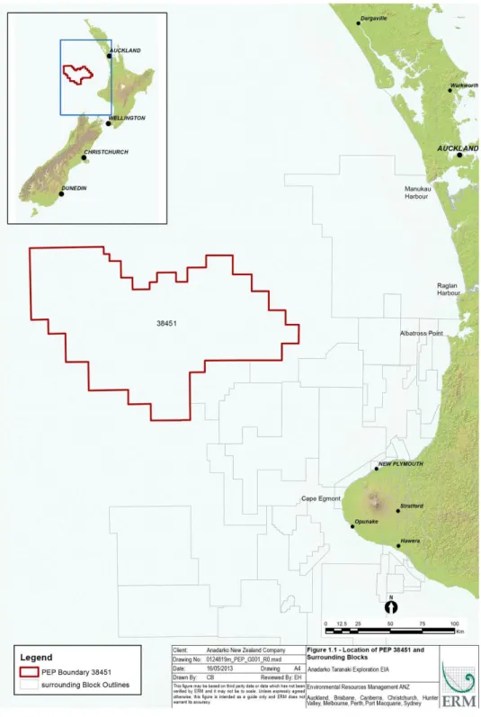
The Project Area extends to the northwest of the Taranaki shelf edge, approximately 100 km off the western coast of NZ’s North Island and across the slope and into the head of the New Caledonia Basin, a major present-day bathymetric trough approximately 4,000 km long (Uruski, 2008) (see Table 1.1 and
Figure 1.1).
Table 1.1: The Project Area Details
PEP Project Area Approximate Project Area Water Depth (m) Distance Offshore (km)
PEP 38451 16,380 km2 1,000-1,500 m
Approx. 115 km north-west of New
Plymouth Latitude and Longitude of the Four Corners of the Project Area
171° 00’ E, 37° 30’ S 173° 22’ E, 38° 03’ S
171° 00’ E, 38° 00’ S 173° 22’ E, 38° 10’ S
1.2 OBJECTIVES AND GENERAL APPROACH
This EIA report covers Anadarko’s exploration drilling campaign which consists of the drilling of a single exploration well within the Project Area (hereafter “the Project”).
This EIA is part of the overall planning effort for Anadarko’s exploration/appraisal program, which is being conducted in accordance with the applicable NZ laws and regulations at the time of issue, international guidelines and procedures, and with Anadarko’s Environment, Health and Safety (EHS) Policy. It should however be noted that at the time of issue of this EIA, regulations under the EEZ Act which will determine how oil and gas exploration drilling activities taking place outside of NZ’s 12 nautical mile (Nm) limit are controlled and consented, have not yet been finalized.
The drilling of the proposed single exploration well currently planned by Anadarko falls outside of this 12 Nm limit and therefore this impact assessment has been submitted to EPA under the transitional arrangements of the EEZ Act
associated with planned petroleum activities (Section 166). During this transitional period, planned petroleum activities that have become discretionary activities under the EEZ Act may commence or continue without the requirement for a formal marine consent after the EEZ Act comes into force subject to the submission of an EIA and various other provisions within Section 166. This EIA has also been prepared in line with the requirements of Section 39 of the EEZ Act, as outlined in Table 1.2.
Table 1.2: Compliance with Section 39 of the EEZ Act
Section 39 Requirement Applicable Section with EIA
1 An impact assessment must –
(a) describe the activity for which consent is
sought; and Section 3.0
(b) describe the current state of the area where it is proposed that the activity will be undertaken and the environment surrounding the area; and
Section 4.0
(c) identify the effects of the activity on the environment and existing interests (including cumulative effects and effects that may occur in NZ or in the sea above or beyond the continental shelf beyond the outer limits of the exclusive economic zone; and
Section 6.0, (drilling impacts)andSection 7.0
(cumulative impacts).
(d) identify persons whose existing interests are likely to be adversely affected by the
activity; and Section 1.5andSection 4.3.
(e) describe any consultation undertaken with persons described in paragraph (d) and specify those who have given written approval to the activity; and
Section 1.5andSection 4.3. (f) include copies of any written approvals to
the activity; and Not legislatively required at this time. (g) specify any possible alternative locations
for, or methods for undertaking, the activity that may avoid, remedy, or mitigate any adverse effects; and
Different methods for undertaking the project activity (such as the choice of drilling vessels etc.) are provided within the Project Description (Section 3.0) and Impact Assessment (Section 6.0). The Project Area and location of the proposed activity is restricted by the boundaries of the PEP owned by Anadarko.
A ‘do nothing’ option is not available as the required exploration work program is detailed within the PEP requirements. If Anadarko were to do nothing, then the PEP would need to be surrendered to the Crown.
(h) specify the measures that the applicant intends to take to avoid, remedy, or
mitigate the adverse effects identified Section 8.0, Table 7.1,and Table 8.1. 2 An impact assessment must contain the
information required by subsection (1) in
This EIA has been prepared in consideration of the scale and significance of the project and it is considered that reasonable efforts have been made to ensure sufficient detail has been provided to enable EPA and persons with existing interests to understand the nature of the activity and its effects on the environment and existing interests.
(a) such detail as corresponds to the scale and significance of the effects that the activity may have on the environment and existing interests; and
(b) sufficient detail to enable the
Environmental Protection Authority and persons whose existing interests are or may be affected to understand the nature of the activity and its effects on the
Section 39 Requirement Applicable Section with EIA (3) The impact assessment complies with
subsection (1)(c) and (d) if the Environmental Protection Authority is satisfied that the applicant has made a reasonable effort to identify the matters described in those paragraphs
Regular consultation with EPA and stakeholders (see Section 1.5andSection 4.3) has been
undertaken through the planning of the project activities and the development of this EIA. (4) The measures that must be specified under
subsection (1)(h) include any measures required by another marine management regime and any measures required by or under the Health and Safety in
Employment Act 1992 that may have the effect of avoiding, remedying, or mitigating the adverse effects of the activity on the environment or existing interests
Reference is made within the EIA to Anadarko’s requirements under relevant NZ and
international regulations, such as Marine Protection Rules Part 200, the Health and Safety in Employment Act 1992 and MARPOL.
The scope of the EIA also follows EHS guidelines produced by the International Association of Geophysical Contractors, International Association of Drilling Contractors and the International Association of Oil and Gas Producers, formerly the Exploration and Production Forum.
This EIA also conforms to the spirit and intent of the NZ Ministry for the Environment (MfE) and EPA’s Impact Assessment Guidance as well as MfE and Maritime New Zealand (Maritime NZ)’s Environmental Best Practice Guidelines for the Offshore Petroleum Industry, although these guidelines are more directly applicable to offshore production facilities rather than all exploration operations.
Table 1.3 highlights the national and international guidelines and protocols used to direct this EIA.
Table 1.3: Guidelines and Protocols Referenced
Guidance Document Comments NZ Legislation
Exclusive Economic Zone and Continental Shelf (Environmental Effects) Act 2012
(EEZ Act)
NZ’s main piece of legislation focused on managing the environmental effects of activities in NZ’s Exclusive Economic Zone (EEZ) and Continental Shelf. The legislation aims to protect NZ’s oceans from the potential environmental risks of activities, like petroleum
exploration, seabed mining, marine energy generation and carbon capture developments.
Secondary legislation for the EEZ Act has not been developed at time of issue of this EIA.
Resource Management Act 1991 (RMA) NZ’s main piece of legislation relating to environmental management on land and within the NZ territorial seas out to 12 Nm.
Health and Safety in Employment (Petroleum Exploration and Extraction) Regulations 2013
Regulations made under the Health and Safety in
Employment Act 1992 concerning health and safety issues in the operation of installations for petroleum exploration and extraction, both onshore and offshore.
Guidance Document Comments
Maritime Transport Act 1994 and the associated Marine Protection Rules and Advisory Circulars under the Maritime Transport Act 1994, plus Maritime Rules
relating to associated supporting maritime activities
Covers a range of shipping and offshore installation-related controls, with most of the marine pollution, marine dumping and incineration provisions only applying outside of the 12 Nm limit. See also
International Conventions.
Note: The administration of provisions within the
Maritime Transport Act 1994, in particular Parts 180 and 200 are under review at time of issue of this EIA.
Biosecurity Act 1993, as amended, including the NZ Import Health Standard for Ballast Water from all Countries and the Import Health Standard for Vessel Biofouling
Provides the legal basis for excluding, eradicating and effectively managing pests and unwanted organisms.
Marine Mammals Protection Act 1978, and the associated Marine Mammals Protection Regulations 1992
Provides protection for all seals, dolphins, whales and porpoises, making it an offence, amongst other things, to harass or disturb marine mammals.
Crown Minerals Act 1991 Provides the framework for allocating rights to prospect, explore or mine minerals that are owned by the Crown. Wildlife Act 1953. An Act to consolidate and amend the law relating to the protection and control of wild animals and birds, the
regulation of game shooting seasons. International Conventions
International Regulations for the Prevention of Collisions at Sea (COLREGS) 1972
International Regulations ratified by NZ and
implemented under Maritime Transport Act1994 regime. The International Convention for the
Prevention of Pollution from Ships, MARPOL, 1973 as modified by the Protocol of 1978
International Convention and implemented under
Maritime Transport Act1994 regime.
United Nations Convention on the Law of the Sea (UNCLOS)
International Convention ratified by NZ and
implemented via various statutes, including the Crown Minerals Act1991, Continental Shelf Act1964, Territorial Sea, Contiguous Zone and Exclusive Economic Zone Act 1977
and the Maritime Transport Act1994. Convention on Biological Diversity International Convention ratified by NZ. General Guidance
Impact Assessment Guidance (MfE and
EPA, no date) NZ Guidelines
Draft Anti-fouling and In-water Cleaning Guidelines (MPI, 2011)
Replaces the Code of Practice for Anti-fouling and In-water Hull Cleaning and Maintenance. Provides guidance on the appropriate use of anti-fouling coatings and the best practice for in-water cleaning and
maintenance of vessels. Environmental Best Practice Guidelines
for the Offshore Petroleum Industry
1.3 LOCATION AND TIMING
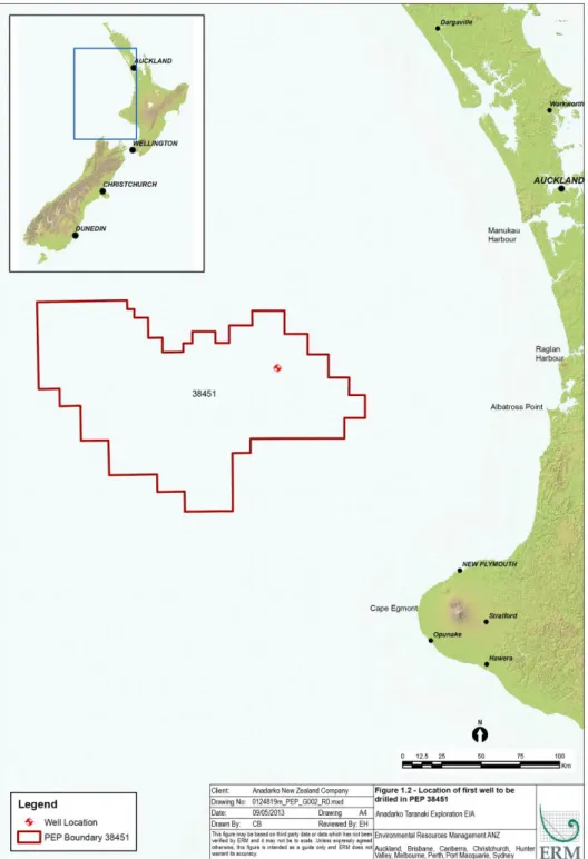
Anadarko’s current Deepwater Taranaki exploration drilling campaign for the Project Area will comprise of drilling one exploration well. The location of the exploration well to be drilled in the Project Area will be at 172°43’52.57” E, 37°53’39.46” S, (see Figure 1.2) and drilling is scheduled to be undertaken in the summer 2013-2014 drilling season (between November/ December 2013 and February 2014). The drilling of this single well is the only exploration/appraisal activity currently planned at this time and is the focus of this EIA.
As noted previously, future activities will be scheduled based on the results of the current one-well campaign. Details of future exploration/appraisal drilling that may be undertaken, along with specific assessments of impact, will be submitted to EPA as separate applications under the EEZ Act once details of the activities are known. These activity-specific assessments will be provided to EPA as updates to this impact assessment and annexes. Information submitted will include well locations, spill trajectory maps, drilling vessel information and an updated EMP, if changes to the EMP are required.
1.4 CONSULTED SOURCES OF INFORMATION
The description of the existing environment presented in Section 4.0 is based on a review of existing data/literature from international and local sources of information. Anadarko accessed the following sources as inputs to the environmental baseline:
Oceanographic and climatological information was obtained from previous reports on the Deepwater Taranaki Basin as well as data acquired by Anadarko from other service providers, e.g. Fugro Global Environmental and Ocean Sciences and MetOcean Solutions;
Biological information was obtained from numerous sources. The general ecological and fisheries baseline was derived from selected species accounts, plenary documents, and other online information compiled by the NZ Ministry for Primary Industries (MPI, formerly the Ministry of Fisheries). Information on threatened species was obtained primarily from the Department of Conservation (DoC)’s Threat Classification Lists (DoC, 2005 and 2011) and the MPI National Aquatic Biodiversity Information System (NABIS, MPI, 2013a) species distribution maps. Information on marine mammals, seabirds, and plankton was obtained from MPI and the Worldwide Fund for Nature (WWF), supplemented with information from the American Cetacean Society’s online fact sheet database and information from the National Institute for Water and Atmospheric Research Ltd. (NIWA). Information on protected natural areas (including marine reserves, benthic protection areas and marine mammal sanctuaries) was obtained from a series of informational reports issued by United Nations Environment Program, DoC and MPI; and
Information on existing interests was obtained from several government and industry sources. Population, ethnicity, and income data were derived from the Statistics New Zealand (Statistics NZ) online database. Information on ports and harbors was obtained from shipping trade sources and NZ Petroleum and Minerals (formerly NZ Crown Minerals). Economic data on fisheries were acquired from Statistics NZ and MPI.
Local specialists were involved in selecting, acquiring, and synthesizing relevant documentation.
1.5 CONSULTATION
Under the current regulatory framework, Anadarko is not legally obliged to undertake consultation with local stakeholders. However, in recognition of the stakeholder interest that could be generated by its proposed exploration activities, Anadarko has initiated and undertaken a program of stakeholder engagement in order to inform relevant groups and individuals of its intended activities. Anadarko also recognizes that formal consultations may be required in the event production activities are undertaken. It is understood that relevant stakeholders will be consulted at the appropriate time through Anadarko or its sub-contractors.
The following key potential stakeholders have been identified. Anadarko has an ongoing program of stakeholder engagement with these groups (see Appendix A
for a register of stakeholder meetings undertaken by Anadarko and Section 4.3.6
for further details regarding Anadarko’s iwi engagement activities):
Iwi: Māori tribal groups that are generally associated with a recognized territory (rohe);
Regional councils adjacent to the Project Area; Adjacent city and district councils;
MfE; EPA;
Maritime NZ; DoC;
The NZ Minister of Energy & Natural Resources; NZ Petroleum and Minerals;
The NZ Ministry of Business, Innovation and Employment, including the former NZ Ministry of Economic Development and NZ Department of Labour; and
Local non-governmental organizations that have an expressed interest in the project.
1.6 LIMITATIONS
The work described herein was conducted following accepted procedures consistent with the current standard of practice in NZ, as well as the objectives and scope of work agreed upon with Anadarko. In accordance with the agreed scope of work, this EIA was prepared on the basis of published information in existence at the time of report issuance (September 2013) that could be readily obtained from relevant online and local sources. The conclusions and recommendations presented herein are based on these data and NZ expert technical review of these and other data and are limited as such. Baseline field studies were not completed as part of this work.
2.0 POLICY, LEGAL, AND ADMINISTRATIVE FRAMEWORK
2.1 NATIONAL LEGISLATION
National legislation applicable to the offshore oil & gas sector and relevant legislation in terms of environmental protection, maritime activities, biosecurity and industrial safety, and cultural and archaeological heritage, includes:
Exclusive Economic Zone and Continental Shelf (Environment Effects) Act 2012 (the EEZ Act);
Resource Management Act 1991 (the RMA) and associated Resource Management (Marine Pollution) Regulations 1998;
Health and Safety in Employment (Petroleum Exploration and Extraction) Regulations 2013;
Maritime Transport Act 1994, and the associated Marine Protection Rules and Advisory Circulars under the Maritime Transport Act 1994, plus Maritime Rules
relating to associated supporting maritime activities (currently under review); Biosecurity Act 1993, as amended, including the NZ Import Health Standard
for Ballast Water from all Countries;
Marine Mammals Protection Act 1978, and the associated Marine Mammals Protection Regulations 1992 ;
Continental Shelf Act 1964;
Territorial Sea, Contiguous Zone, and Exclusive Economic Zone Act 1977; Wildlife Act 1953; and
DoC 2012 Code of Conduct for Minimising Acoustic Disturbance to Marine Mammals from Seismic Survey Activities (DoC Code of Conduct).
The EEZ Act
The EEZ Act was developed and enacted in 2012 in order to address the jurisdictional inconsistencies in the above legislative instruments and to fill an overarching gap in the regulation of activities within NZ’s EEZ and continental shelf. The EEZ Act seeks to manage the environmental effects of activities in NZ’s oceans and to protect them from the potential environmental risks of activities like petroleum exploration, seabed mining, marine energy generation and carbon capture developments.
Whilst the EEZ Act has been formally enacted, secondary legislation (i.e. regulations) enforcing the principles of the EEZ Act for exploration drilling had not been finalized at time of issue of this EIA. As a result, this impact assessment has been submitted to EPA under the transitional arrangements of the EEZ Act
associated with planned petroleum activities (Section 166) and the requirements of Section 39 of the EEZ Act. During this transitional period, planned petroleum activities that have become discretionary activities under the EEZ Act may commence or continue without the requirement for a formal marine consent after the EEZ Act comes into force subject to the submission of an EIA and various provisions within Section 166.
Marine Protection Rules Part 200
Under the Marine Protection Rules Part 200: Offshore Installations – Discharges (Part 200), as amended in 2013 (Maritime NZ, 2013) a detailed description of all identified potential environmental impacts, including any possible social, cultural and economic implications that may result from any operational discharges or spill of oil or other substances (such as that provided within an EIA) is required as part of a drilling installation’s Discharge Management Plan (DMP) that must be submitted to and approved by Maritime NZ. The requirements of Part 200 are provided within a separate DMP document prepared by Anadarko. The DMP excluding annexes that has been submitted to Maritime NZ for approval has been appended to this EIA as Appendix B in order to provide further information on the management and mitigation measures employed during the drilling activity.
Other Regulatory Updates
Other relevant legislative developments underway at the time of issue of this EIA include the proposed amendments to the Maritime Transport Act 1994 contained within the Marine Legislation Bill 2012.
Amongst other things, the Marine Legislation Bill 2012 seeks to transfer responsibility for regulating certain discharges and dumping of waste under Parts 180 and 200 of the Marine Protection Rules from Maritime NZ to the EPA.
2.2 INTERNATIONAL CONVENTIONS, TREATIES, AGREEMENTS, AND
PROGRAMS
The following international agreements and conventions may affect petroleum activities in marine waters off NZ.
International Regulations for the Prevention of Collisions at Sea, 1972
Also known informally as the nautical rules of the road, the International Regulations for the Prevention of Collisions at Sea (COLREGS) specifies the conduct of vessels on the high seas, and provides a standard set of operational expectations and navigation procedures for maritime vessels. NZ ratified the convention in 1972. COLREGS is implemented in NZ under the Maritime Transport Act 1994 regime in NZ.
International Convention for the Prevention of Pollution from Ships, 1973 as modified by the Protocol of 1978
The International Convention for the Prevention of Pollution from Ships (MARPOL) is the main international convention covering prevention of pollution of the marine environment by ships from operational or accidental causes. It is a combination of two treaties adopted in 1973 and 1978 respectively, and updated by amendments through the years. NZ is signatory to Annex 1 – Oil, Annex II – Noxious Liquid Substances Carried in Bulk, Annex III - Harmful Substances Carried in Packaged Form and Annex V – Garbage. These annexes are enacted through the Maritime Transport Act 1994 and supporting instruments.
United Nations Convention on the Law of the Sea (UNCLOS), 1982
UNCLOS was completed in Montego Bay, Jamaica, on the 10th of December 1982. The objective is to set up a comprehensive new legal regime for the sea and oceans; including rules concerning environmental standards as well as enforcement provisions dealing with pollution of the marine environment. NZ ratified the convention in 1996, and it is in force in NZ via a number of statutes including the Crown Minerals Act 1991 (through which petroleum exploration permits are awarded) and the Maritime Transport Act 1994 and related Rules.
Convention on Biological Diversity, 1992
The objective of the Convention on Biological Diversity is the conservation of biological diversity, the sustainable use of its components, and the fair and equitable sharing of the benefits arising out of the utilization of genetic resources. The Convention is the first international agreement to view biological diversity as a resource over which nation states have sovereign rights. Biological diversity in signatory nations has thus attained the same status as mineral and other natural resources. NZ ratified the convention in 1993.
3.0 PROJECT DESCRIPTION
3.1 EXPLORATION DRILLING METHOD
Exploration drilling is typically the next step in the process of confirming findings from a marine seismic survey (MSS). This consists of drilling one or more wells to confirm the presence of a hydrocarbon reservoir and to assess the geology of the area.
Exploration/appraisal drilling is conducted in order to investigate offshore natural gas and petroleum deposits. Data gathered (e.g. subsea geological features and mineral resources) will help to determine whether the development of the Project Area is economically viable as well as whether the installation of production wells is feasible. Information gathered will also help determine the optimal location, planning and installation of production wells.
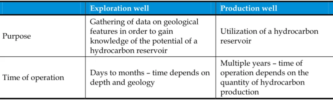
It is important to note that drilling exploration wells is one of the steps conducted prior to the installation and operation of production wells. Table 3.1 cites the main characteristics of each of the wells.
Table 3.1: Main Characteristics of an Exploration Well and a Production Well
Exploration well Production well Purpose
Gathering of data on geological features in order to gain knowledge of the potential of a hydrocarbon reservoir
Utilization ofa hydrocarbon reservoir
Time of operation Days to months – time depends on depth and geology
Multiple years – time of operation depends on the quantity of hydrocarbon production
3.2 EXPLORATION DRILLING ELEMENTS
Exploration drilling will be executed on behalf of Anadarko by specialist drilling contractors. The specific elements (vessels, equipment, timing etc.) that will constitute the drilling activities may vary through the exploration/appraisal program. This information will be appended to this EIA (see Appendix C) along with vessel and activity specific assessments of impact and submitted as separate applications under the EEZ Act once details of the activities are known.
The following section provides information regarding the first drilling vessel which will be used in the Project Area plus information regarding the drilling specifications for the current single exploration well campaign.
3.2.1 Drilling Vessel Options
The first drilling vessel planned to be used for this project is the drillship Noble Bob Douglas. The drilling vessels for any subsequent wells are not currently identified, but these are also expected to be a dynamically positioned drillship. An alternative to a dynamic positioned drillship would be a semi-submersible drilling vessel, which is likely to also have dynamic positioning:
Sixth-generation dynamically positioned drilling vessels allow for drilling of exploration/appraisal wells with minimal subsea disturbance due to its ability to operate without moorings. Given the required drill depths of the Deepwater Taranaki Basin and the program specifications, Anadarko’s exploration program will need to utilize a modern drilling vessel. Sixth-generation models typically comprise of a vessel with an opening in the mid-section (known as a “moonpool”) with a derrick suspended over it.
Semi-submersible drilling vessels have a partially submerged structure below the water line. Water is used as ballast control to maintain flotation and stability. The drilling vessel is usually held in position by using dynamic positioning or mooring (use of anchors).
Drilling vessels will be selected based on drilling plans, technical requirements, and availability.
In general, these vessels have similar capacities and equipment. Both options provide living quarters for all personnel involved in the drilling operation. They also include offices, a radio room, emergency medical equipment, drilling fluid laboratory and facilities, galley, mess, meeting rooms, recreational rooms, and laundry facilities.
Both options generally accommodate over 100 people. The frequency of crew changes has not been determined but typically crew changes for similar projects occur every four weeks. Crew change transfers between the mainland and the drilling vessel will take place by vessel or helicopter.
Principal components for both types of drilling vessels include: Derrick, draw-works and top drive;
Casing and pipe racks;
Normal use and emergency generators;
Drilling fluid circulation and solids removal equipment;
Bulk storage containers for fuel, drilling fluids, cement, fresh water, brine, mineral oil, etc.;
Safety and fire-fighting equipment; Potable water system;
Safety devices, including Blow-Out Preventers (BOPs) and control system (see
Cranes and pipe handling equipment; Sewage treatment system; and
Personnel accommodations and support facilities.
Circulation of drilling fluid and cuttings is powered by electric pumps, which also power air compressors. Control of the well (to avoid a release of hydrocarbons from the subsurface reservoir to be penetrated by the drilling) is achieved using a BOP, a series of valves and diverters that direct and control sudden blow-backs of pressurized gases or fluids from the well. The drilling activity is continually monitored using a system of instruments, gauges and sensors.
All drilling vessels will comply with the Import Health Standard for Ships‘ Ballast Water from All Countries (Biosecurity Act 1993), Maritime Transport Act 1994, MARPOL and the relevant NZ Marine Protection Rules in having current International Oil Pollution Prevention Certificates and International Sewage Pollution Prevention Certificates, applicable certifications and current inspections for the vessel class, pollution control equipment and systems, discharges at sea, crewing standards and requisite liability insurances.
The following sections provide information on the drilling vessel selected for the first single well exploration drilling campaign planned for November/December 2013 (the drillship Noble Bob Douglas).
3.2.1.1 Noble Bob Douglas
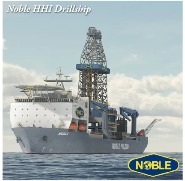
The Noble Bob Douglas (see Figure 3.1), a sixth-generation dynamically positioned drilling vessel, has been selected for this drilling activity and as such, the vessel allows for drilling of the exploration well with minimal subsea disturbance. Given the required drill depths and program specifications, the Project will need to utilize a modern drilling vessel. Sixth-generation models typically comprise of a vessel with an opening in the mid-section (known as a “moonpool”) with a derrick suspended over it.
Specifications for the Noble Bob Douglas are provided in Table 3.2 and can also be used as a reference for other vessel(s) that may be used within the exploration/ appraisal program as future vessel(s) are anticipated to have similar characteristics. As a dynamically positioned vessel, no moorings or anchoring (including storm moorings) of the Noble Bob Douglas will be required at the proposed drilling location.
Figure 3.1: The Noble Bob Douglas, a Sixth Generation Dynamically Positioned Drillship
Source: Noble (no date)
Table 3.2: Specifications of the Noble Bob Douglas
Type Sixth Generation Drillship: Noble Bob Douglas
Length (overall) 229 m
Breadth 36 m
Depth 19 m
Operating Draft 11 m
Ocean Transit Draft 0 m
Water Depth Maximum 3,048 m
Drilling Depth 12,200 m
Accommodation 210 berths
3.2.2 Drilling Vessel Storage Capacities
To provide adequate supplies of material for continuous operations and emergency conditions, drilling vessels usually maintain on-board bulk storage capacity for several weeks of activity. Table 3.3 presents storage and utility capacities of the Noble Bob Douglas.
Table 3.3: Storage Capacity of the Noble Bob Douglas
Material Capacity
Liquid drilling fluid 3,210 m3
Drill water 3,200 m3
Potable water 1,600 m3
Fuel oil 6,820 m3
Bulk drilling fluid 450 m3
Bulk cement 450 m3
Sack material 10,000 sacks
Source: Noble (no date)
3.2.3 Part 200 Pre- and Post-Drilling Environmental Monitoring
As per the requirements of Part 200 (see Section 2.1) Anadarko is required to undertake environmental monitoring in order to detect marine environmental impacts resulting from discharges from drilling vessels (Part 200.25). Anadarko has an environmental monitoring plan approved by Maritime NZ that includes pre-drill and post-drill environmental monitoring for its proposed single well exploration drilling activity. The environmental monitoring program includes: Characterization of the water column by profiling the physicochemical
attributes and collecting samples to document metals and hydrocarbon levels; and
Collection of sediment samples to characterize macroinfauna and document physicochemical attributes.
Details of the environmental monitoring plan are provided within the DMP required under Part 200 which Anadarko has submitted to Maritime NZ for approval (see DMP Annex G).
3.2.4 Drilling Vessel Mobilization
It is expected that the drilling vessel (drillship or semi-submersible) will mobilize to drilling locations fully equipped to initiate drilling activities. As previously mentioned, the first well will be drilled with the Noble Bob Douglas, a dynamically positioned drillship. Once near the drilling location, dynamically positioned ships communicate with transponders placed on the sea floor that communicate
Mobilization routes for the drilling vessels within NZ waters have not been finalized; however it is recognized that entry of exploration vessels within the 12 Nm limit may require additional biosecurity provisions. Transit through the Cook Strait may also require consideration of mechanisms through which risks of damage to sub-sea infrastructure and interactions with other shipping can be avoided. The Project will comply with all relevant maritime navigation rules, such as Maritime Rules Part 22: Collision Prevention (Maritime NZ, 2009) in terms of obligatory appropriate radio, navigational aids and good navigational practices, seamanship and shipping lanes. The requirements of the Marine Mammals Protection Act 1978 and associated regulations will also be adhered to during all mobilization activities of the drilling vessel and support vessels.
The drill ship will be equipped with a moonpool, or an area on the deck that is open to the sea through which the drilling occurs. Once in position, the casing and drilling assembly will be prepared and put into position for drilling. Movement of equipment and fluids onto and around the ship is done using various capacity cranes, hoists, winches, hoses, pipes and pumps.
Prior to the start of drilling a Remotely Operated Vehicle (ROV) will be used to survey the pre-drilling conditions of the seafloor (i.e. stability and to confirm absence of sensitive habitats).
3.2.5 Typical Drilling Technique
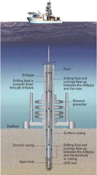
The drilling technique that will be employed will consist of a standard rotary system with a top drive (see Figure 3.2). This comprises a crane like structure (the derrick) mounted on the drill floor. A draw works or hoisting drum is also mounted on the drill floor at the base of the derrick. A drilling line (made up of wire rope) passes from the hoisting drum to the top of the derrick through an arrangement of pulleys known as the ‘crown block’, and is finally fastened via another series of pulleys (the ‘traveling block’) to a hook. The system operates like a crane and can be lifted and lowered within the derrick.
The top drive is suspended from the hook, which is fastened to the drill string. The drill string consists of uniform lengths of hollow steel pipe, screwed together. When the drilling starts, a rotary drill bit is fastened to the lower end of the drill pipe and lowered by the hoisting drum through a rotary table attached to the floor. The top drive supplies the rotary motion for the drill bit.
3.2.6 Well Installation
Deepwater offshore drilling is performed through careful advancement of drilling equipment to a desired depth beneath the sea floor. Drilling fluids are used to help control and manage drilling activities. The design of the first well (including drilling fluid program) and associated planned activities are described in the following section.
3.2.6.1 Well Construction
The initial step of drilling the well in deep water involves jetting in 36 inch structural pipe to support the load of the well control equipment and subsequent casing strings. The process is called “jetting” because the drilling fluid is pumped through the holes (jets) in the drill bit causing most of the disintegration of the sediment and rock that is being penetrated. As drilling advances, a well is cased with progressively smaller diameter steel pipe to prevent the hole from collapsing. Following the casing of one section, drilling of the next section continues with a smaller-diameter bit than the previous one. After jetting, a 26 inch hole will be drilled which will be cased with 20 inch casing run with high pressure wellhead housing.
A steel tube, known as the marine riser, conveys drilling fluids and cuttings from the well, isolating it from the sea, up to the drilling vessel. Subsea well control equipment (BOPs as described in Section 3.2.6.3 below), is also run on the riser and latched to the high pressure housing. Drilling while under reaming will proceed with a 17 X 20- inch hole drilled into the top of the Eocene geological section before the intermediate 16 inch pipe is set. After cementing the 16 inch casing, a 14-3/4 X 17- inch hole will be drilled into the Upper Cretaceous and a 13-3/8- inch liner will be set and cemented at ~3400 m. A 12-1/4- inch hole will then be drilled to penetrate the potential hydrocarbon bearing zones in the Cretaceous section. Both logging while drilling and wireline logging operations at the end of the 12-1/4- inch hole section will determine the presence of producible hydrocarbons. Based upon these logging results the well will be either cased (possibly tested, see Section 3.2.7.3), or temporarily abandoned or alternatively the well will be decommissioned (see Section 3.2.8.1).
Internationally recognized best practices for deepwater exploration drilling will be used to plug and temporarily or permanently abandon the well. The wellhead will be left in place in order to leave the well in a safe and environmentally sound manner and have it available for future use. Refer to Figure 3.2 for a diagram of well drilling mechanics.
The first well in the Project Area, Romney, will be drilled to a depth of approximately 3,055 m below the seabed or 4,575 m below sea level (in a water depth of approximately 1,520 m), as follows:
36- inch casing will be jetted down to approximately 72 m below the seabed (1,592 m below sea level) using seawater. The hole will be swept clean of cuttings at intervals with high viscosity guar gum and gel sweeps;
The 26- inch interval will be drilled to 790 m below the seabed (~2,310 m below sea level) with seawater. The hole will be swept clean of cuttings with high viscosity guar gum and gel sweeps. A 20 inch conductor pipe will be run and cemented to isolate this section;
The BOP stack will be run and tested after cementing the 20- inch casing in place;
The 17 X 20- inch segment will be drilled to 1,490 m below the seabed (~3,010 m below sea level) with Non-Aqueous Based Drilling Fluid (NABF);
16- inch casing will be run and cemented in place;
The 14-3/4 X 20- inch segment will be drilled to 1,855m below the seabed (~3,375m sea level) with NABF;
13-3/8- inch casing will be run and cemented in place;
A segment of 12-1/4- inch will be drilled up to 3,055 m below the seabed (~4,575 m below sea level) with a NABF;
The well will undergo wireline testing; and
Based on the results of the wireline testing, the well will be permanently decommissioned or temporarily abandoned.
Consistent with international industry practice, Anadarko plans to establish a minimum 500 m radius buffer zone around the drilling vessel, which will be advised through a Notice to Mariners issued through Maritime NZ. The buffer zone will be kept clear of all unauthorized vessels, primarily through direct communication with vessels approaching the rig’s location which will be monitored by radar and visual observation. The 500 m radius has been adopted by the United Kingdom Offshore Operators Association for all vessels approaching an offshore oil and gas facility for the safety and security of the vessels.
Figure 3.2: Drilling Technique
Source: Schlumberger (no date), http://www.glossary.oilfield.slb.com
3.2.6.2 Drilling Fluids
During the drilling process, drilling fluid is pumped down the inside of the drill pipe and exits at the drill bit. The purpose of the drilling fluid is to:
Generate hydrostatic pressure (produced by the drilling fluid’s weight), to control the down hole pressure and prevent formation fluids from entering the well bore;
Reduce friction between the drill string and the wellbore;
Remove the rock cuttings from the bottom of the hole and transport them to the surface and suspend the drill cuttings in the hole when circulation is interrupted;
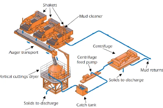
Drill cuttings and fluids returning to the drilling vessel will pass through solids control equipment (shale shakers) prior to discharge to reduce the retention of drilling fluids on the cuttings. Shale shakers remove drilled solids by passing material through a wire-cloth screen that vibrates. The drilling fluid and solids smaller than the wire mesh pass through the screen, while larger solids are retained on the screen. Additionally, centrifuges and a cuttings dryer will also be used to further remove the drilling fluid from the drill solids. Centrifuges use centrifugal force to separate the drilling fluid from smaller solids, allowing the drilling fluid to be returned to the circulating system and the solids to be discharged overboard. Cuttings discharged overboard are tested periodically to ensure the efficiency of the solids control equipment and to ensure appropriate standards (i.e. MARPOL and provisions outlined in the DMP required under Part 200 which Anadarko has submitted to Maritime NZ for approval (see Appendix B, Section 7.1: Operational Discharges) are met. Figure 3.3 depicts a typical schematic of shale shaker components.
Figure 3.3: Diagram of a Typical Shale Shaker
Source: International Association of Oil and Gas Producers (2003), http://www.ogp.org.uk/pubs/342.pdf Drilling fluids fall in one of two classes, depending on their principal liquid phase component: Water-Based Drilling Fluids (WBFs), and NABFs. The drilling fluid program proposed by Anadarko includes the use of WBFs and synthetic NABFs, which may include low-toxicity linear or branched paraffin, internal olefins, linear alpha olefins, esters, and/or poly-alpha olefins.
A variety of chemicals may be added to the drilling fluid to provide the following functions:
Fluid loss control: The layer of drilling fluid on the wall of the well bore
prevents the passage of liquids into the surrounding rock formation. In water based drilling fluids, bentonite is the main material for fluid loss control although other additives such as starch and cellulose, all naturally occurring substances, are also used.
Lost circulation: When drilling through some formations drilling fluid can be lost through fissures in the surrounding rock, decreasing the amount of drilling fluid returning to the drilling vessel to be cleaned and reused. Naturally occurring filamentous, flake, granular or fibrous materials are used to prevent lost circulation when the drill bit enters a fractured or porous formation. Typical materials include mica and ground nut shells.
pH control: Lime and caustic soda are used to manage the alkalinity of the drilling fluid to a pH of 9 to 10. This ensures the optimal performance of the polymers in the drilling fluid and manages the bacterial activity.
Pressure control: Barite (barium sulfate) is commonly used as a weighting agent to manage down-hole pressure.
Table 3.4 shows the drilling fluid program and expected discharges for the first well (Romney) in the Project Area based on current information. The final drilling fluid program may change based on input from the drilling contractor, information about the drilling location and conditions. The fluid program includes both WBF and NABF.
Table 3.4: Romney Drilling Fluid Program and Projected Discharges
Bit
(inches) Depth Below Sea Level Fluid Type
Estimated Discharges Cuttings (bbls*) WBF Discharged (bbls) Residual on Cuttings Discharged(bbls) Discharge Location
36 From top of sea bed to 72m seawater 297.4 590.4 - Seafloor
26 72-790m seawater 2288.4 7614.7 - Seafloor
20 790-1,490m NABF 1026.4 - 70.8 Overboard Drilling
Vessel
17 1,490-1,855m NABF 386.7 - 26.7
Overboard Drilling
Vessel
12.25 1,855-3,055m NABF 631.4 - 43.6 Overboard Drilling
Vessel
Total 4630.3 8205.1 141.1
Notes:
It is estimated that 8,205.1 barrels (bbls) (1304.5 m3) of WBF and 2585.8 bbl (411.1 m3) of WBF cuttings will be discharged for a well drilled to a depth of 2330m. During the well intervals when NABF is used, it is estimated that 2044.5 bbl (325.0 m3) of cuttings will be discharged. As outlined above, the NABF itself will not be discharged, other than small amounts that adhere to discharged materials, due to the use of a shale shaker. Recovered NABF will be collected and transported to shore for storage/reuse in a drilling fluid plant. Management of drill cuttings is further described in Section 8.3.4.
Additionally, in deep water drilling locations, mitigation against gas hydrate formation can be required if gasses are encountered. Gas hydrates can be formed in and around a well head and BOP. Presence of gas hydrate in the reservoir can be a safety and environmental hazard and may potentially lead to a well blowout. In that case, the BOP operation can be impaired by the hydrate formation. NABF can be used in place of WBF to prevent problems with drill string sticking and hole collapse in water-solvent strata. In addition, prevention of hydrate formation can be most effectively achieved by the use of a NABF system.
3.2.6.3 Well Control and Blowout Prevention
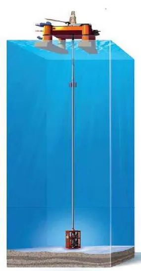
In addition to vigilant monitoring and management of the fluids and installation of casing in each section of a well, a BOP will be installed. The role of the BOP is to prevent the escape of down-hole pressure and fluids. The BOP is comprised of a series of individual spill control devices used to seal and control any extreme pressures or uncontrolled flow from the reservoir. BOPs are installed on the wellhead at the seabed after the top hole sections have been drilled (see Figure 3.4).
The BOP stack is certified to international standards, including API 16A, 16C, 6A, NACE MR 0175/ISO 15156-1 and DNV-OS-E101.
Although the Romney well is not expected to encounter any zones of abnormal pressure, the BOP used will be rated for well pressures in excess of those expected to be encountered in the wells. In an emergency, the BOP can be controlled from the drilling vessel. Testing of the BOP will be conducted during drilling operations
The BOP fluid is a water-based liquid with a small amount of additives to improve lubricity and for corrosion control. This fluid is considered by Anadarko to be environmentally safe.
Figure 3.4: Illustration of Subsea Blowout Preventer Stack
Source: Oil States International, Inc. (no date),
http://www.oilstates.com/fw/main/Drilling-Systems-615.html
3.2.7 Formation Evaluation
3.2.7.1 Well Logging
Well logging is performed to obtain a detailed record (well log) of the subsurface formations (e.g. rock, gas, petroleum etc.) penetrated by the borehole and to monitor the progress of the drilling. There are many logging techniques that can be carried out either during or after the drilling process. The various types of tests may include standard, electric, acoustic, radioactivity, and density induction. These tests may consist of visual inspections of samples brought to the surface or physical measurements made by instruments lowered into the hole. Well logging is typically performed by technicians of a specialist logging company.
In the event that the applied logging technique involves radioactive sources (e.g. wire logging), stringent policies and procedures are in place for these operations. These policies and procedures cover the handling, storage, transportation, and use of radioactive sources during the operation. Without exception, the requirements imposed will meet or exceed all NZ governmental regulatory standards for safety and the environment.
3.2.7.2 Coring
Coring is carried out in order to collect samples (core samples) of rock formations to assess hydrocarbon potential and other characteristics relevant for drilling operations. Cores from the wells will be inspected and analyzed by different techniques and equipment depending on the type of data desired.
3.2.7.3 Reservoir Testing
When the target zone of the well has been reached and if the logging results are positive, testing of the reservoir interval may be carried out. The purpose of the testing is to evaluate the potential production capacity of the well. Testing may be conducted in more than one zone as drilling progresses and hydrocarbon intervals are encountered.
The detailed design of any well-test and the number of tests to be carried out will be dependent upon the results of well logging. In general, reservoir tests are performed by isolating a portion of the borehole and piping fluids to the drilling vessel via specialized completion equipment under carefully controlled conditions. On the drilling vessel several steps are taken to evaluate the hydrocarbons: the hydrocarbons can be separated into oil and gas fractions; the rate at which they are produced is measured; and samples are taken. The testing period will typically last for 48 hours during which the well is flowed at different rates prior to being shut in. The measurements taken help determine the capacity of the reservoir encountered. For the proposed exploration well to be drilled in the summer 2013-2014 campaign, no cased hole drill stem test will be conducted, therefore no discharges associated with these activities will occur (i.e. flaring). Samples of liquids and gases recovered during testing may be further evaluated through laboratory analyses or other tests, both on board and later by specialized contractors. Liquids and gases recovered for testing will be collected and shipped to an approved onshore waste disposal firm for disposal.
3.2.8 Demobilization
Following the drilling, the well will be either temporarily or permanently abandoned depending on the data which were collected during drilling and testing. Wellheads will be left in place, as the water depth precludes damage in the future and allows for future utility of the wellbore.
Following the drilling of the first well in the Deepwater Taranaki Basin, the Noble Bob Douglas will be mobilized to the Canterbury Basin and subsequently demobilized out of country.