Abstract— By penetrating the SCADA system, an intruder may remotely operate a power system using supervisory control privileges. Hence, cybersecurity has been recognized as a major threat due to the potential intrusion to the online system. This paper proposes a methodology to evaluate the cybersecurity vulnerability using attack trees. The attack tree formulation based on power system control networks is used to evaluate the system, scenario, and leaf vulnerabilities. The measure of vulnerabilities in the power system control framework is determined based on existing cybersecurity conditions before the vulnerability indices are evaluated. After the indices are evaluated, an upper bound is imposed on each scenario vulnerability in order to determine the pivotal attack leaves that require countermeasure improvements. The proposed framework can be extended to security investment analysis.
Index Terms-- Attack Tree, Cybersecurity, Defense Systems, Power System Control, Security Vulnerability.
I. INTRODUCTION
INCE the September 11, 2001 terrorist attack, the level of vigilance has been raised to prevent attacks on power grids. Conventional design of power systems does not provide a power system with the protection against cyber attacks. The threats include sending control commands via the supervisory control system. Effects of a cyber attack include loss of production, degradation of the online control performance, and inability to take preventive and corrective actions in time. Damages caused by cyber attacks can be catastrophic.
The widespread interconnectivity of the power system control network poses significant risks to the nation’s critical operations. Without proper control of these computer systems, individuals or organizations may disrupt the operations from remote locations for malicious purposes [1]. Recent findings include plans of terrorism to disrupt the U.S. power grid [2]. Recent NERC directives make it mandatory to undertake cybersecurity vulnerability assessment at the operator locations and to take corrective measures [3]. The NERC security document and ISO/IEC17799 Standard specify guidelines for cybersecurity in power systems [3-5]. In addition, computer crime and security survey conducted by the Computer Security Institute (CSI) indicated inadequate investment to security awareness training in utilities [6]. The lack of security awareness is increasingly problematic as the cyber attacks become more sophisticated. There have been novel contributions to identify vulnerability of cybersecurity for a power grid. A testbed has been set up in [7] with
C.-W. Ten, C.-C. Liu, M. Govindarasu are with the Electrical and Computer Engineering Department, Iowa State University of Science and Technology, Ames, IA, 50010 USA (e-mails: [email protected], [email protected], [email protected]).
possible intrusion scenarios to recognize and mitigate the effect of attacks. In [8], a new threat is assumed in generation control that hackers could access to tamper with the generator control loop parameters. This may lead to destabilization and tripping of critical units on the power grid.
The contribution of this paper is an analytical method to measure the vulnerabilities of a control center and its related computer systems. An attack tree model is used as a framework to derive the quantitative vulnerability measures. Potential intrusion scenarios can be determined with different combinations of security breaches in order to penetrate the system. The penetration may allow an intruder to use SCADA control capabilities to take undesirable actions, causing serious damages. This paper provides a systematic procedure to evaluate vulnerability indices.
The remaining of this paper is organized as follows. Section II provides an overview of attack tree modeling and control center networks. The attack tree modeling and methodology is described in Section III. Section IV analyzes intrusion scenarios in case studies and provides examples of a quantitative vulnerability analysis. Pivotal attack leaves are determined by imposing an upper bound on the scenario vulnerability. Section VII is the conclusion and future research.
II. ATTACK TREE MODELING
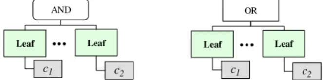
An attack tree is a graph that connects more than one attack leaf from each node [9-10]. An attack tree may consist of a multi-level hierarchy in a predecessor-successor structure that captures the possible ways to achieve sub-goals. The top node of an attack tree is the ultimate goal with combinations of sub-goals. Each attack leaf may include one or more defense nodes that are direct successors of the attack leaf. Defense nodes provide countermeasures. In Fig. 1(a), the box labeled
c1 is a countermeasure for attack leaf on the left side. An attack leaf can be an element of different intrusion scenarios, depending on the node connectivity associated with it. The predecessors of each attack leaf are nodes that are attributed with logic operators “AND” or “OR.” Each predecessor node is specific for the given leaf node. Fig. 1 shows attack trees with “AND” and “OR” configurations. All leaves lead to an AND box will have to be penetrated in order to move up the attack tree, i.e., a subsystem has been penetrated. On the other hand, in Figure 1(b), if one of the attack leaves is penetrated, it is sufficient to move up the attack tree.
OR Leaf c1
...
Leaf c2 Leaf c1...
Leaf c2 AND(b) An attack leaf with logic operator "OR" (a) An attack leaf with logic operator "AND"
Fig. 1. Attack Leaves with “AND” or “OR”
Chee-Wooi Ten, Student Member, IEEE, Chen-Ching Liu, Fellow, IEEE, Manimaran Govindarasu, Member, IEEE
Vulnerability Assessment of Cybersecurity for
SCADA Systems Using Attack Trees
S
A. Control center communication networks
Fig. 2 shows the communication paths within power system control networks. Entities in the control center, substation automation system, distribution management system, Independent System Operator (ISO), and power plant process control system are interlinked. The interdependency of the communication and power system infrastructures plays an essential role to wide area monitoring and control. The communication link is an optical fiber network or a microwave system. Backup control centers provide coverage for disaster scenarios that may disable the primary control center, e.g., loss of data communication, critical monitoring and control facilities. In addition, Web-Based SCADA is the Internet-Based SCADA and application services to utility industry that provides convenient and low cost maintenance by out-sourcing the maintenance services. This is implemented using a client-server architecture though Internet. Power Plant Process Control System (Generators) Substation Automation System (Buses) Distribution Management System (loads) Primary Control Center Backup Control Center Primary ISO Control Center Backup ISO Control Center Web-Based SCADA
Primary Path of Communication Secondary Path of Communication
Fig. 2. Real-Time Communication within Power System Control Networks The overall communication and computer infrastructure is complex. Deficiencies of security guidelines and policy enforcements may result in penetration to the networks. Vulnerability assessment for each entity is to identify the access points to the network as well as cyber assets. This includes comprehensive password policy enforcement and constant auditing of unused default ports available.
B. Introduction to the methodology
A cybersecurity vulnerability index is a measure of the likelihood that an attack tree or attack leaf will be compromised by hackers [11]. Each attack leaf may have weaknesses that are prone to attack. The vulnerability index ranges from 0 to 1, from the most invulnerable (0 value) to the most vulnerable (1 value). There are separate vulnerability indices for each attack leaf and each intrusion scenario. There is also an overall system vulnerability index. All indices range from 0 to 1.
A vulnerability index is determined based on: (1) evidence of attempted intrusions; (2) existing countermeasures and
improved countermeasures [12]; and (3) password policy
enforcement [13]. The vulnerability index is evaluated with
the hypothesis listed in Table I [14]. Three conditions are defined in Table I. Condition 1 states that there is no evidence to suggest that there are intrusion attempts for the system. Condition 1 is not met when there are credible evidences of malicious attempts based on electronic data. Condition 2 is
met when there are one or more countermeasures implemented for an attack leaf. Any technology that is applied to defend the attack leaf would satisfy condition 2. An example is a web server installed with a firewall that monitors the access to prevent malicious intrusions through online traffic. Password implementation for each attack leaf is considered for assessment. Poor password practices result in unauthorized access. A system can face the risks of unauthorized access, even though it may be password protected. Condition 2 and condition 3 may influence condition 1. For instance, implementation of the new technological countermeasures can reduce the likelihood of intrusions. Applying boundary protection in a firewall with a set of rules can also reduce access from anonymous users. This would reduce attempted intrusions and enhance system security. The other example is that condition 3, with stronger password policies, would also protect the system from being compromised. However, this does not change the number of attempts.
TABLEI
RULES FOR CONDITIONS 1,2, AND 3
Conditions Rules Condition 1
The system is free of intrusion attempt that is concluded from the electronic evidences in the system.
Condition 2 At least one or more countermeasures are implemented to protect an attack leaf. Condition 3
At least one or more password policies are enforced corresponding to each attack leaf.
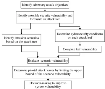
III. VULNERABILITY ASSESSMENT OF CYBERSECURITY The procedure to evaluate vulnerability indices is depicted in Fig. 3. As shown in the figure, the procedure starts with an analysis of the attack objectives. Then the attack tree and countermeasures are established. The system vulnerability index is obtained by evaluating the scenario vulnerability and
the leaf vulnerability for selected scenarios and the
corresponding attack leaves.
Determine cybersecurity conditions on each attack leaf Compute leaf vulnerability Evaluate scenario vulnerability
Identify possible security vulnerability and formulate an attack tree
Determine pivotal attack leaves by limiting the upper bound of the scenario vulnerability
Decision-making to improve system vulnerability Identify intrusion scenarios
based on the attack tree
Identify adversary attack objectives
This section describes the procedure to evaluate the vulnerability indices: (a) cybersecurity conditions, and (b) evaluation of vulnerability indices.
A. Cybersecurity conditions
This section evaluates the cybersecurity conditions,
ω
, that is a preliminary evaluation before the specific vulnerability indices related to leaves and scenarios are calculated. The cybersecurity condition assessment is based on technological countermeasures and enforcement of the password policy.The cybersecurity condition is measured by a number
ω
, that assumes the values of 0. 0.5, or 1. The value 0 indicates that the system condition is invulnerable while value 1 indicates the system is vulnerable.1)
ω
=0.00:If [(Condition 1) AND (Condition 2) AND (Condition 3)],
then
ω
=0.00All conditions in Table I are satisfied. Advanced countermeasures are deployed and comprehensive password policies are enforced. There is no evidence that the system is subject to malicious attempts.
2)
ω
=0.50:If <[(Condition 1) AND (Condition 2)] OR [(Condition 1) AND (Condition 3)] OR [(Condition 2) AND (Condition 3)]> , then
ω
=0.50Any two of the conditions in Table I are satisfied. 3)
ω
=1.00:If( [(Condition 1) OR (Condition 2) OR (Condition 3)] OR
(None of the condition)], then
ω
=1.00Only one of the conditions is met or, None of the conditions are satisfied.
B. Evaluation of vulnerability indices
This section is concerned with the cybersecurity vulnerability of an attack tree. There are four steps to assess the security vulnerability: (1) Identifying the intrusion scenarios, (2) Evaluating vulnerability indices for the system, intrusion scenarios, and attack leaves, (3) Evaluating security improvements, and (4) Identifying the pivotal leaves.
1) Identifying the intrusion scenarios from the attack tree:
First, the intrusion scenarios from the attack tree are identified. Then, the possible intrusion scenarios are enumerated. Each of the intrusion scenarios is the combination of attack leaves that are formed with “AND” or “OR” attributes configured in the attack tree. The leaf vulnerability index
v
( )
G
k of each attack leaf is evaluatedonce all the intrusion scenarios are determined. The scenario vulnerability is the product of the corresponding attack leaf vulnerabilities.
2) Evaluating vulnerability indices:
There are three security vulnerability indices: (i) system vulnerability, (ii) scenario vulnerability, and (iii) leaf
vulnerability. The system vulnerability,
V
s , is thevulnerability of an attack tree determined from the scenario vulnerability, as shown in (1). K is the total number of intrusion scenarios. A vector of scenario vulnerabilities is given in (2) where
I
=
{
i i
1, ,
2L
,
i
K}
is a set of intrusion scenarios. TheV
sis determined from the maximum value of the scenario vulnerability set. Each intrusion scenario is a possibility that leads to successful penetration of the system. The vulnerability of a scenario is the product of leaf vulnerabilities where each scenario vulnerability is formed with a different subset of S. Scenario vulnerability indices are given in (3) wheres s
1,
2,
L
,
s
K∈
S
andS
=
{
1 2
, ,
L
,
n
}
. The symbols
represents an index subset of S that is the universal index set of attack leaves and n is the total number of attack leaves. ( ) ( ) ( ){
1 2}
(
( ))
S K V =maxV i ,V i ,L,V i =max V I (1)( )
( ) ( )
1 2( )
T K I =⎡⎣V i V i V i ⎤⎦ V L (2)( )
( )
( )
( )
( )
( )
( )
1 2 1 2 K j j s j j s K j j s V i v G V i v G I V i v G ∈ ∈ ∈ ⎡ = ⎤ ⎢ ⎥ ⎢ ⎥ = ⎢ ⎥ =⎢ ⎥ ⎢ ⎥ ⎢ ⎥ ⎢ = ⎥ ⎢ ⎥ ⎣ ⎦∏
∏
∏
V M (3)A leaf vulnerability is evaluated by (4). The cybersecurity condition number
ω
must be identified first. The basis for evaluation is to pre-determine the leaf vulnerability condition with respect to the evidence of attempted intrusions, technological countermeasures, and password policy enforcement, which was discussed in Section III(A). To evaluate the strength of technological countermeasures, the total number of countermeasure types is determined, which is denoted by a constant 5 in (4). Then, the ratio between the countermeasures implemented at the specific attack leaf to the total number of countermeasure types is determined, whereT
C
n
is the number of countermeasures types implemented at an attack leaf [12]. The strength of the ratio is deducted from 1 to convert it to the vulnerability ratio.( )
{
(
(
)
)
{
( )
}
}
(
)
(
)
{
( )
}
{
}
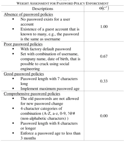
1 5 0 0 1 5 3 T T P C k P C n C v G n C ω ω ω ω ⎧ ⋅ − ⋅ Θ > ⎪ =⎨ = ⎪ − Θ ⎩ max , max , , max , max (4)Second, the weighting factor of the password policy enforcement is evaluated. Each password policy should be assigned with a value
( )
PC
Θ based on Table II. The weight assignment of the password policy enforcement indicates the level of difficulty to crack the password. In Table II, an increment of (approximately) 0.33 point starting from the strong password policies of 0 value for
( )
PC
Θ is used. The strongest password policies deter or prolong the cracking process. Neither brute-force trials nor social engineering techniques can break through in a short period of time.
The highest weight assignment of the password policy enforcement is taken as the measure that would be the most vulnerable of the set. The notation
C
Prepresents the set of four levels of password policies as shown in Table II. If the password policy enforcement has a password length of more than 8 characters long, thenΘ
( )
c
P=
0 00
.
. If the factory default password is not removed, thenΘ
( )
c
P=
0 67
.
. The overall value of( )
PC
Θ is the maximum among the password policy levels that are applicable for the specific attack leaf, i.e.,
max
{
Θ
( )
C
P}
=
0 67
.
.In (4), for
ϖ
>
0
, the final evaluation of leaf vulnerability is based on the more vulnerable of the two measures, which is the higher value among the two sets,C
P,
C
T∈
C
whereP T
C
⊄
C
, andC
T⊄
C
P. On the other hand, forϖ
=
0
, the more vulnerable of two countermeasures is divided to reflect the fact that 3 measures are used for cybersecurity conditions, i.e., evidence of malicious attempts, technology countermeasures, and password policy enforcement.3) Evaluating security improvements
Security improvement can be achieved by a replacement or additional countermeasures. The improvements for an attack leaf and intrusion scenario can be measured with the implementation of the defense nodes denoted as v G′
( )
and( )
V i′ respectively, for the leaf and scenario vulnerability after
an improvement is implemented. The degree of improvement for a leaf vulnerability is given by
( ) ( ) ( )
100v G′ v G v G
⎡ − ⎤ ×
⎣ ⎦ % and similarly for scenario
improvement.
4) Determine the pivotal leaves
The system vulnerability is evaluated based on (2). Improvements of the leaf vulnerability can lead to higher system vulnerability. To identify the pivotal leaves for system vulnerability enhancement, an optimization problem is proposed:
min
V
S (5) s.t.V
( )
I
≤
V
( )
I
(6)v
( ) ( )
G
≤
v
G
(7) where0
≤
v
( ) ( )
G
, V
I
≤
1
The combination of scenario vulnerability is subject to the configuration of an attack tree because system vulnerability is expressed as a function of scenario vulnerability. The objective of this formulation is to minimize system vulnerability by lowering the upper bound of the scenario vulnerability,V
( )
I
. By doing so, the pivotal leaf combination for system improvement is determined. Theimprovement is observed through changes in
V
( )
I
. A uniform upper bound for all leaf nodes can be enforced, such as 0.5 for all leaves. The vector of upper boundsv
( )
G
is then a vector with all elements equal to 0.5. This is to ensure the least secured leaf nodes are properly enforced. The pivotal leaves are the leaf nodes inv
( )
G
with a reduced value compared to the corresponding values before the upper bounds are reduced.TABLE II
WEIGHT ASSIGNMENT FOR PASSWORD POLICY ENFORCEMENT
Descriptions
( )
PC
Θ
Absence of password policies
No password exists for a user account
Existence of a guest account that is known to many, e.g., the password is the same as username
1.00
Poor password policies
With factory default password Set with combination of username, company name, date of birth, that is possible to crack using social engineering
0.67
Good password policies
Password length with 7 characters long
Implement maximum password age
0.33
Comprehensive password policies
The old passwords are not allowed for new password change
4-character categories of combination (A-Z, a-z, 0-9, !@# (non-alphabetic characters) ) Password length with 8 characters or longer
Enforce a password age to less than 3 months
0.00
IV. CASE STUDIES
The methodology proposed in the previous section is applied to study cases here. The purpose is to identify the access points of power system control networks and evaluate the network vulnerability. The objective of the proposed attack tree is focused on penetration of the control center intranet from others, e.g., substation intranet with Virtual Private Network (VPN) connection. An attack tree based on Fig. 2 is constructed; the case studies are subject to specific business practices. The model incorporates the existence of factory default password and insufficient security improvement [16]. The attack leaves include countermeasures to improve the system vulnerability.
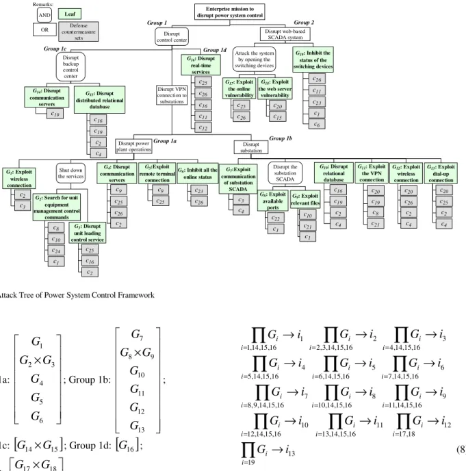
An attack tree illustrated in Fig. 4 consists of disruptions through a power plant, substation, or web-based SCADA. The disruptions include sabotage on computer systems and power systems. These combinations may result in an intrusion into the control center. To derive the scenario combination, groups of attack leaves are arranged as follows:
Group 1a:
⎥
⎥
⎥
⎥
⎥
⎥
⎦
⎤
⎢
⎢
⎢
⎢
⎢
⎢
⎣
⎡
×
6 5 4 3 2 1G
G
G
G
G
G
; Group 1b:⎥
⎥
⎥
⎥
⎥
⎥
⎥
⎥
⎦
⎤
⎢
⎢
⎢
⎢
⎢
⎢
⎢
⎢
⎣
⎡
×
13 12 11 10 9 8 7G
G
G
G
G
G
G
; Group 1c:[
G
14×
G
15]
; Group 1d:[ ]
G
16 ; Group 2:⎥
⎦
⎤
⎢
⎣
⎡
×
19 18 17G
G
G
Each group represents the security flaw of a sub-network from power plant, substation networks, and web-based SCADA system. Groups 1a and 1b represent a disruption of power plant operations and substation automation. Security breaches in these groups may also result in penetration to the control center. Groups 1c and 1d represent a disruption of the backup control center and real-time services in the primary control center. The importance of a backup control center is to take over functions of the primary control center under extreme circumstances. Communication, relational database, and real-time application services in control centers are critical elements. Group 2 represents the disruption of Web Based SCADA system where security breaches in a web server may be exploited by intruders.
Each intrusion scenario is derived from attack leaves, where
G
1,
G
2,
L
,
G
19 are attack leaves. Intrusion scenarios are expressed as follows:1 16 , 15 , 14 , 1
i
G
i i→
∏
= 2 16 , 15 , 14 , 3 , 2i
G
i i→
∏
= 4,14,15,16 3i
G
i i→
∏
= 4 16 , 15 , 14 , 5i
G
i i→
∏
= 5 16 , 15 , 14 , 6i
G
i i→
∏
= =∏
→
16 , 15 , 14 , 7 6 i ii
G
7 16 , 15 , 14 , 9 , 8i
G
i i→
∏
= 8 16 , 15 , 14 , 10i
G
i i→
∏
= 9 16 , 15 , 14 , 11i
G
i i→
∏
=∏
=→
16 , 15 , 14 , 12 10 i ii
G
∏
=→
16 , 15 , 14 , 13 11 i ii
G
∏
=→
18 , 17 12 i ii
G
∏
=→
19 13 i ii
G
(8) wherei i
1, ,
2L
,
i
13∈
I
These attack leaves include countermeasures that can be technological countermeasures or password policy enforcements. The description of each countermeasure is listed in the Appendix. The setsC
P=
{
c
1,
c
2,
L
,
c
7}
and{
c
8,
c
9c
26}
C
T=
L
are countermeasure sets for password and technological countermeasure, while{
1 2 26}
C
=
c c
,
,
L
,
c
is the universal countermeasure set.( )
G
v
andv
′
( )
G
are computed in accordance with the configuration of the attack tree; the results are given in the Appendix. The leaf vulnerability and its improvement are depicted in Figs. 5(a) and (b). The vulnerability improvement for each attack leaf is depicted in Fig. 5(b). By eliminating the factory default password and enhancing security countermeasures, the leaf vulnerability has been improved. According to (4), the number of countermeasures types implemented at an attack leaf is essential because it influences the vulnerability of a leaf. Attack leaves 5 and 17 do notdisrupt power system control
Disrupt power plant operations Disrupt substation Disrupt control center Disrupt web-based SCADA system G5:Exploit remote terminal connection G4: Disrupt communication servers Shut down the services
G2: Search for unit
equipment management control commands G3: Disrupt unit loading control service
G6: Inhibit all the
online status G7:Exploit communication of substation SCADA Disrupt the substation SCADA G11: Exploit the VPN connection Disrupt backup control center G14: Disrupt communication servers G15: Disrupt distributed relational database Disrupt VPN connection to substations G16: Disrupt real-time services
Attack the system by opening the switching devices G19: Inhibit the status of the switching devices G17: Exploit the online vulnerability G18: Exploit
the web server vulnerability G8: Exploit available ports G9: Exploit relevant files OR Leaf Defense countermeasure sets AND G10: Disrupt relational database G12: Exploit wireless connection G1: Exploit wireless connection G13: Exploit dial-up connection Group 1a Group 1b Group 1c Group 1 Group 2 Group 1d c8 c10 c24 c3 c2 c1 c25 c16 c2 c9 c25 c26 c2 c9 c25 c23 c26 c3 c4 c22 c1 c10 c21 c1 c16 c19 c2 c4 c20 c19 c8 c21 c20 c26 c2 c4 c20 c25 c2 c4 c19 c19 c16 c2 c4 c25 c26 c16 c11 c12 c25 c26 c20 c15 c26 c11 c23 c1 c6
improve if the same technological countermeasure is implemented on that attack leaf. (The improvement is based on the same countermeasure technology, i.e., access control.) Attack leaf 3 has the greatest improvement. This is due to the combination of technological countermeasure types and elimination of the guest account. Eliminating the factory default password and guest account improved the leaf vulnerability.
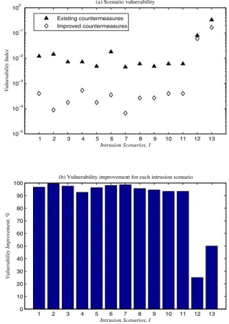
In the next step,
V
( )
I
andV
′
( )
I
are evaluated using (3). Each intrusion scenario is the product of attack leaves in (8). The scenario vulnerability is plotted in Fig. 6. Note that the logarithmic scale is used in Fig. 6(a) to highlight the difference betweenV
( )
I
andV
′
( )
I
. As shown in Fig. 6(a), the first 11 intrusion scenarios have a greater improvement. However, intrusion scenarios 12 and 13 do not show much improvement. Fig. 6(b) shows vulnerability improvement for each intrusion scenario. Finally, the system vulnerability indices before and after the improved countermeasures are implemented,V
sandV
s′
, respectively, are determined fromV
( )
I
andV
′
( )
I
. The system vulnerability indices,V
sandV
s′
, are 0.33 and 0.13, respectively. 1 2 3 4 5 6 7 8 9 10 11 12 13 14 15 16 17 18 19 0 0.2 0.4 0.6 0.8 1 Attack Leaf, G Vulnerability Index(a) Leaf vulnerability
Existing countermeasures Improved countermeasures 1 2 3 4 5 6 7 8 9 10 11 12 13 14 15 16 17 18 19 0 10 20 30 40 50 60 70 80
(b) Vulnerability improvement for each attack leaf
Attack Leaf, G
Vulnerabilty Improvement, %
Fig. 5. Leaf Vulnerability with Existing and Improved Countermeasures It is desirable to identify critical attack leaves that are influential for the improvement of system vulnerability. Table III shows the numerical results based on (5)-(7). The upper bound of the
v
( )
G
is set to 0.5 which represents an intermediate level of vulnerability. Table III shows the required changes for each attack leaf with a different upper bound of scenario vulnerability shown in each column. The highlights are changes from the output of optimization. Bylimiting
V
( )
I
from 1 to 0.000001, it is seen that attack leaves 7, 15, 16, 17, 18, 19 are the pivotal leaves to improve the security measure in order to satisfyV
( )
I
.V. CONCLUSION AND FUTURE WORK
The proposed methodology can be used to systematically evaluate the vulnerability and improvements based on cybersecurity conditions, technological countermeasures, and password policy enforcement. Security improvement of an attack tree depends on the total number of countermeasure types and password policy enforcement on each attack leaf. Case studies of the power system control networks have been performed to determine the vulnerability indices. To avoid manual, exhaustive search on each attack leaf, an optimization problem is formulated that can be solved to determine pivotal leaves for security improvements.
The formulation of attack trees does not capture the sequence in which attack leaves are penetrated in a scenario, however, an attack tree can be used as the foundation to emulate penetration testing, confirm the hypothesis, and study security flaws. Besides, attack trees can include budgetary constraints to evaluate system vulnerability that determines the optimal security investment based on this framework.
1 2 3 4 5 6 7 8 9 10 11 12 13 10−5 10−4 10−3 10−2 10−1 100 Intrusion Scenarios, I Vulnerability Index
(a) Scenario vulnerability
Existing countermeasures Improved countermeasures 1 2 3 4 5 6 7 8 9 10 11 12 13 0 10 20 30 40 50 60 70 80 90 100
(b) Vulnerability improvement for each intrusion scenario
Intrusion Scenarios, I
Vulnerability Improvement, %
Fig. 6. Scenario Vulnerability with Existing and Improved Countermeasures TABLEIII
FOUR UPPER BOUNDS ON SCENARIO VULNERABILITY FOR EACH LEAF ( )
VI 1 0.01 0.0001 0.000001
0.3611 0.3611 0.4355 0.4407
v(G1)
0.0000 0.2890 0.2744 0.2733 v(G2) v’(G2) 0.2200 0.2200 0.2200 0.2196 0.2600 0.2600 0.2573 0.2561 v(G3) v’(G3) 0.2000 0.2000 0.2000 0.1996 0.2600 0.2600 0.2529 0.2508 v(G4) v’(G4) 0.1300 0.1300 0.1300 0.1280 0.2600 0.2600 0.2529 0.2508 v(G5) v’(G5) 0.2600 0.2412 0.2486 0.2580 0.2700 0.2700 0.2629 0.2608 v(G6) v’(G6) 0.1300 0.1300 0.1300 0.1280 0.3300 0.2700 0.0961 0.0940 v(G7) v’(G7) 0.3877 0.0000 0.0000 0.0000 0.3300 0.3300 0.3276 0.3270 v(G8) v’(G8) 0.2200 0.2200 0.2200 0.2196 0.3300 0.3300 0.3276 0.3270 v(G9) v’(G9) 0.2200 0.2200 0.2200 0.2196 0.3300 0.3300 0.3229 0.3208 v(G10) v’(G10) 0.2000 0.2000 0.1995 0.1980 0.2700 0.2700 0.2629 0.2608 v(G11) v’(G11) 0.2000 0.2000 0.1995 0.1980 0.2200 0.2200 0.2129 0.2108 v(G12) v’(G12) 0.2000 0.2000 0.1995 0.1980 0.2200 0.2200 0.2129 0.2108 v(G13) v’(G13) 0.2000 0.2000 0.1995 0.1980 0.0000 0.0000 0.0000 0.0000 v(G14) v’(G14) 0.0923 0.0923 0.0996 0.1007 0.0000 0.0000 0.0000 0.0000 v(G15) v’(G15) 0.0000 0.0000 0.0048 0.0000 0.0000 0.0000 0.0000 0.0000 v(G16) v’(G16) 0.0000 0.0000 0.0048 0.0000 0.0000 0.0000 0.0000 0.0000 v(G17) v’(G17) 0.0000 0.0000 0.0000 0.0000 0.1062 0.1363 0.1238 0.1238 v(G18) v’(G18) 0.0000 0.0000 0.0000 0.0000 0.0000 0.0000 0.0000 0.0000 v(G19) v’(G19) 0.0000 0.0000 0.0000 0.0000 VI. Appendix C Descriptions 1
c Eliminate guest account 2
c Eliminate factory default password 3
c Implement password age 4
c 4-character categories of combination password policy is enforced
5
c Enforce a password age less than 3 months 6
c Implement password length at least 8 characters 7
c Increase password change frequency 8
c Install computer forensic tools 9
c Implement biometric for authentications 10
c Install integrity checkers to monitor alternations to system files 11
c Implement patch management system to update security patches
available 12
c Install antivirus software 13
c Install content management to monitor web and messaging
applications 14
c Set the rule of the IP address that is allowed
15
c Implement digital certificates 16
c Monitor the security event logs to determine malicious
operations 17
c Configure different port of the services 18
c Document and audit the use of each static IP addresses 19
c Install intrusion detection system to monitor the traffic within
the network 20
c Enhance with the policy of firewall in substation LAN 21
c Eliminate administrative right to limited users like vendors who
can change the configuration 22
c Install network analyzer to monitor malicious traffic 23
c Install a redundant system in case of urgent need to switch 24
c Install a scanner to identify malicious traffic of the network 25
c Install smart tokens to establish strong authentication 26
c Audit the user rights that contain privileges accessing critical
commands
Improved Countermeasures Set Used for Each Attack Leaf and Descriptions Attack Leaf Evidence of Attempted Intrusion Technological Countermeasures Password Policy Enforcement Firewall 1 Malicious attempt detected Antivirus
Factory default password remains 2
Absence of malicious
attempt
Authentication Guest account 3
Malicious attempt detected
Firewall Factory default password remains User rights and
privileges are set Personal firewall 4 Absence of malicious attempt Antivirus
Factory default password remains Implemented password age 5 Malicious attempt detected
User rights and
privileges are set Password length with at least 8 characters Firewall Implemented password
age 6
Absence of malicious
attempt User rights and privileges are set
Password length with at least 8 characters 7
Malicious attempt detected
User rights and
privileges are set No password 8
Absence of malicious
attempt
Firewall Guest account
9
Absence of malicious
attempt
Firewall Guest account
User rights and privileges are set
Factory default password remains 10
Absence of malicious
attempt Firewall Password length with at least 8 characters 11
Absence of malicious
attempt
Firewall Implemented password age
Firewall Factory default password remains 12 Malicious attempt detected in the logs of substation LAN
Anti-virus Password length with at least 8 characters User rights and
privileges are set
Factory default password remains 13
Malicious attempt
detected Intrusion detection system
Password length with at least 8 characters User rights and
privileges are set
Password length with at least 8 characters 14
Malicious attempt
combination User rights and
privileges are set
Factory default password remains 15
Malicious attempt
detected File integrity checkers
Password length with at least 8 characters User rights and
privileges are set
Factory default password remains Antivirus 4-character categories of
combination 16 Absence of malicious attempt Firewall
Old passwords are not allowed to replace as
new Firewall 4-character categories of
combination 17
Absence of malicious
attempt Antivirus Password length with at least 8 characters User rights and
privileges are set
4-character categories of combination 18 Attempted logon with more than 3 time Firewall
Password length with at least 8 characters Authentication Password length with at
least 8 characters User rights and
privileges are set Guest account 19
Malicious attempt detected
Digital certificates 4-character categories of combination Implemented Countermeasures for Each Attack Leaf
VII. ACKNOWLEDGMENT
The authors gratefully acknowledge the contributions of Srdjan Pudar, Mohammad Fraiwan, and the support of Electric Power Research Center (EPRC) at Iowa State University.
VIII. REFERENCES
[1] J. Eisenhauer, P. Donnelly, M. Ellis, and M. O’Brien, “Roadmap to secure control systems in the energy sector,” Energetics of Columbia, MD, January 2006.
[2] Government Accountability Office (GAO) Report to Congressional Requesters, “Critical Infrastructure Protection: Department of Homeland Security Faces Challenges in Fulfilling Cybersecurity Responsibility,” GAO-05-434, May 2005.
[3] “NERC cybersecurity standards (final version),” http://www.nerc.com/~filez/standards/Cyber-Security-Permanent.html. [4] G. N. Ericsson and A. Torkilseng, “Management of information
security for an electric power utility – on security domains and use of ISO/IEC 17799 standard,” IEEE Transactions on Power Delivery, Vol. 20, No. 2, April 2005, pp. 683 – 690.
[5] E. Goetz, “Cyber security of the electric power industry,” Institute for Security Technology Studies at Dartmouth College, December 2002. [6] L. A. Gordon, M. P. Loeb, W. Lucyshyn, and R. Richardson, “CSI/FBI
computer crime and security survey,” Computer Security Institute, 2005.
[7] J. Tang, R. Hovsapian, M. Sloderbeck, J. Langston, R. Meeker, P.G.McLaren, D. Becker, B. Richardson, M. Baca, J. Trent, Z. Hartley, R. Parks, and S. Smith, “The CAPS-SNL power system security testbed,” Proc. CRIS, Third International Conference on Critical Infrastructures, Alexandria, VA, September 2006.
[8] C. L. DeMarco and Y. Braden, “Threats to electric power grid security through hacking of networked generation control,” Proc.CRIS, Third International Conference on Critical Infrastructures, Alexandria, VA, September 2006.
[9] B A. P. Moore, R. J. Ellison, and R. C. Linger, “Attack modeling for information security and survivability,” CMU/SEI-2001-TN-001, March 2001.
[10] B. Schneier, “Attack trees: modeling security threats,” Dr. Dobb’s Journal, December 1999.
[11] “Vulnerability assessment methodology for electric power infrastructure,” US Department of Energy, Office of Energy Assurance, September 30, 2002.
[12] Government Accountability Office (GAO) Report to Congressional Requesters, “Information security: technologies to secure federal systems,” GAO-04-467, March 2004.
[13] C. E. Landwehr, “Computer security,” Springer-Verlag, July 2001. [14] M. Amin, “North America’s electricity infrastructure: are we ready for
more perfect storms?” IEEE Computer Society: Security & Privacy, 2003, pp. 19–25.
[15] J. Jung, C.–C. Liu, M. Hong, M. Gallanti, and G. Tornielli, “Multiple hypotheses and their credibility in on-line fault diagnosis,” IEEE Transactions on Power Delivery, Vol. 16, No. 2, April 2001, pp. 225– 230.
[16] “Cybersecurity standards workshop,” user manual for the workshop, North American Electric Reliability Council, September 28-29, Minneapolis, MN.
IX. BIOGRAPHIES
Chee-Wooi Ten (S’00) received his BSEE and MSEE at Iowa State University, Ames, in 1999 and 2001 respectively. He is currently a Ph.D. student at Iowa State University. In 2000, he was a summer intern with Mid-American Energy Control Center in Des Moines. Mr. Ten was an application engineer with Siemens Energy Management and Information System (SEMIS) in Singapore from January 2002 to July 2005. His area of interest includes Cybersecurity Modeling for Energy Infrastructure, Applications for Power System Control, and Economic Optimization.
Chen-Ching Liu (F’94) received his Ph.D. degree from the University of California, Berkeley. He is currently Palmer Chair Professor of Electrical and Computer Engineering at Iowa State University. During 1983-2005, he was a Professor of Electrical Engineering at the University of Washington, where he also served as an Associate Dean of Engineering from 2000-2005. Dr. Liu received an IEEE Third Millennium Medal in 2000 and the IEEE Power Engineering Society Outstanding Power Engineering Educator Award in 2004. He is serving as Chair of the Technical Committee on Power System Analysis, Computing and Economics (PSACE), IEEE Power Engineering Society. Professor Liu is a Fellow of the IEEE.
Manimaran Govindarasu (M’99) is currently an Associate Professor in the Department of Electrical and Computer Engineering at Iowa State University (ISU). He received his Ph.D. in Computer Science and Engineering from Indian Institute of Technology (IIT) Madras, India in 1998. He received Young Engineering Research Faculty Award at ISU in 2003. His research expertise is in the areas of resource management in real-time systems and networks, overlay networks, network security, and their applications to critical infrastructures such as electric grid. Dr. Govindarasu has published over 100 peer-reviewed research publications. He is co-author of the text “Resource Management in Real-Time Systems and Networks,” MIT Press, 2001. He has given tutorials on Internet infrastructure security in conferences, such as IEEE Infocom 2004 and IEEE ComSoc TutorialsNow (2004), and served as workshops co-chair, symposium co-chair, and session chair on many occasions.