CS261 Project - Sensor Network Programming for
“Dummies”
Mark Hempstead
Division of Engineering and Applied Sciences Harvard University
Abstract
Although, the ultimate goal of WSNs is to place powerful data col-lection and analysis capability in the hands of scientists, current programming environments are cumbersome often requiring some-one with a PhD in computer science in order to construct a basic program. Our research group is currently developing a next gen-eration system-on-chip (SoC) for wireless sensor network applica-tions. Therefore, this work proposes a graphical and modular pro-graming environment for sensor network applications on the Har-vard Ultra Low Power Event Driven Architecture.
The proposed system provides a set of parameterizable macros that the user can connect together to define an application. The back-end of our system uses the connection information to piece define correct interrupt-service routines (ISR) routines. This macro method allows us to use the Hardware features of our system such as hardware acceleration and application level power management. Our SoC is currently in the circuit design phase and we plan to complete the implementation of our programing system by the time parts return from IBM.
1
Introduction
Wireless sensor networks (WSNs) are poised to transform the way society interacts with the physical world, driven by an explosion of systems research in sensor networks. Sensor networks have been proposed and deployed for a wide variety of applications such as habitat monitoring, and emergency medical response. Many industry and academic groups are currently developing hardware for the next gener-ation of sensor network nodes which will be extremely low power with additional functionality. Although, the ultimate goal of WSNs is to place powerful data collection and anal-ysis capability in the hands of scientists, current program-ming environments are cumbersome. Steven Glaser, a struc-tural engineer who has deployed sensor networks to study the strength of structures, sums up the problems of sensor net-work programing quite well: “It is our opinion that a scientist or engineer who wants to use wireless sensor node technol-ogy should not have to earn a Computer Science Ph.D. in or-der to do so.[1]” Prof. Glaser expresses the frustration shared by many in the scientific community that wireless sensor net-works should be used as a tool by scientists without requiring the support of several computer science graduate students.
This work proposes a graphical and modular programing en-vironment for basic sensor network monitoring applications with the goal of placing the power of WSNs in the hands of the scientists.
There is an ulterior motive to the development of the graphical programing interface; my group is currently de-veloping a system-on-chip (SoC) for sensor network appli-cations and we would like to make it easy for researchers to use our platform[3]. Our hardware architecture supports the notion of event processing in hardware, includes mem-ory mapped hardware accelerators, and supports fine-grained power management at the application level. We would like to be able to hide the details of the hardware accelerator pro-graming from the user and provide a clear parameterizable interface for programing the system. The goal of this project is to provide a way for a technical person (but not a CS PhD) to quickly create a sensor network application for our plat-form in an intuitive manner. In the future we hope to port our programming environment to other sensor network applica-tions.
The proposed system provides a set of parameterizable macros that the user can connect together to define an ap-plication. The back-end of our system uses the connection information to piece define correct interrupt-service routines (ISRs). This macro method allows us to use the Hardware features of our system such as hardware acceleration and ap-plication level power management. Our SoC is currently in the circuit design phase and we plan to complete the imple-mentation of our programing system by the time parts return from IBM.
The organization of the paper is as follows: Section 2 pro-vides an overview of our hardware architecture that this sys-tem is being developed for and an overview of related pro-graming systems. Section 3 details the requirements of the system and describes why porting TinyOS is not optimal for our system. Section 4 describes the design of both the user interface of our system and the backend specific to our hard-ware architecture.
2
Related Work
This section describes some of the related and background work for this project. First we discuss the details of our event-driven platform and then discuss other related projects.
2.1
Harvard ULP Architecture
2.1.1
Architectural Motivation and Goals
Our system employs an event driven architecture designed for the regular nature of sensor network applications. The general-purpose microcontroller spends most of the time in a low power state only awaking to handle irregular events such as system reprogramming. The event processor, a small state machine, handles all system interrupts and transfers data be-tween modularized slave components. Keeping the above discussion in mind, we summarize our architectural design goals.
1. Event-Driven Computation: We seek to eliminate un-necessary event-processing overhead by building a true event-driven hardware platform.
2. Hardware Acceleration to Improve Performance and
Power: Our aim is to build a system composed of
sev-eral components that are optimized for specific tasks. The intuition that drives this goal is that it is better to split the functionality of the system into several small components, each of which can be micro-managed for lower power consumption, as opposed to a monolithic computing engine that does not provide knobs for fine-grained power management.
3. Exploiting Regularity of Operations within an
Appli-cation: We expect that specific hardware components
will be able to handle regular events in an applica-tion input stream, thus avoiding the use of the general-purpose components, and minimizing energy con-sumption. Since irregular events occur infrequently, the penalty for using the general-purpose components of the system is justifiable.
4. Optimization for a Particular Class of Applications: Our architectural innovations aim to optimize the common-case behavior of monitoring applications for low-power, while still providing general-purpose pro-cessing capability for a broader class of applications. 5. Modularity: The system that we propose to build must
be modular to allow different sets of hardware compo-nents to be combined into a larger system that is best suited to a particular type of application. A modular system architecture is easily extensible.
6. Fine-grained Power Management Based on
Computa-tional Requirements: One of the main themes driving
our design is the possibility of configuring resource usage (for lower power consumption) of the sensor
Power lines for Memory Segments Memory uController General Processing (Irregular Events) POW E R CONTROL DATA ADDRESS INTERRUPT Event Processor Interrupt Processing Power Management (Regular Events) Unhandled Interrupts
Power Enable Lines
Off Chip Components (for this Version)
Off Chip Bus Signals Tester Ctrl Signals VDD for Tester Bus Signals Bus Signals Interrupt to Process
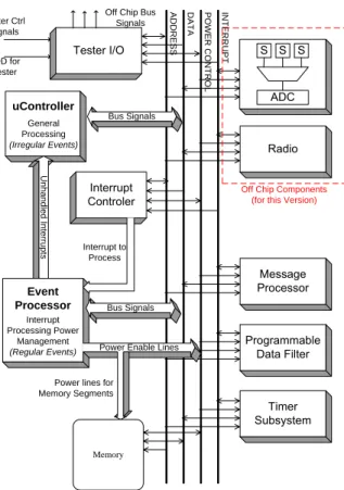
Figure 1:Block Diagram of System Architecture
network devices on-the-fly according to computational demands. Fine-grained power management support at the architecture allows the designer to use advanced circuit tricks (such as VDD gating) to future decrease leakage current.
2.1.2
Architecture Description
The system architecture is illustrated in Figure 1. There are two distinct divisions within the system in terms of the ability of the component to control the system bus. We refer to the components that have full control of the system address lines as master components and the remaining blocks that do not facilitate transfers on the databus as slave components. The system bus has three components – an interrupt bus, a data bus, and power control lines. The slaves respond to read or write requests from the master side of the data bus, thus allowing the masters to read information content and control execution of the slaves. The two master devices consist of a general-purpose microcontroller and a small state machine, the event processor.
A key benefit of the modular design of our architecture is the ability to employ fine-grained power management of in-dividual components (both masters and slaves). Selectively turning-off components, using VDD-gating, allows us
min-imize leakage power. For example, the general-purpose mi-crocontroller core could be relatively complex and power-hungry when active, but can be VDD-gated most of the time when idling. The event processor handles all interrupts, dis-tributes tasks to slave devices, and wakes up the microcon-troller only when necessary (rarely). A more detailed archi-tecture description is available[3].
2.1.3
Implications for the Graphical Programing
Sys-tem
The event driven architecture describe provides significant hardware support for various tasks therefore it is important that the programing system provide abstractions to aid the user at the same time retaining the power of the architecture. It is important that the user be able to utilize the hardware accelerators without knowledge of the specific memory ad-dresses or required configuration bits. At the same time the user should be able to make power management decisions at the block level to maintain the energy efficiency of our hard-ware system.
2.2
Other Related Systems
Several researchers have looked in to ways of program-ing sensor network systems and graphical programprogram-ing tech-niques. This section details some of those approaches. Our proposed programming system will be unique because not only does it provide graphical programming for wireless sen-sor networks but it also will support the new Harvard ULP architecture.
2.2.1
Graphical Programing Systems
Many scientists use LabVIEW from National Instruments as a graphical development platform[7]. LabVIEW provides the flexibility of the programming language and includes specific tools for typical measurement and testing applica-tions. The web documentation for LabVIEW indicates that it can be used to develop software for various platforms (even sensor networks). However, we have not heard of a success-ful deployment using LabVIEW, clearly more research is re-quired.
Over the years many researchers have investigated graph-ical programing languages and systems. Marian Petre pro-vides a good overview of these systems and points out that graphical systems are not better just because they are graphic. Instead it is the secondary clues that represent rela-tionships between components in the system that provide the true power of graphical programming[8].
2.2.2
Programing Wireless Sensor Networks
Researchers at Harvard University are working on high level languages for sensor network programing and have coined the term “Macroprogramming”[6]. This group looks to se-lect certain regions of the sensor network for programming and hides low level details from the user. This work is not yet available for consumption by the scientific community.
It also isn’t clear if these abstractions will allow for the fine-grained power management and control available on the Har-vard ULP architecture.
Members of the TinyOS[4] Community have developed graphical simulation and debugging tools. PowerTOSSIM is a simulator for TinyOS based applications with the ability to estimate the power consumption of notes[9]. TinyDB is an application which allows the user to query the network and task sensors to collect data[5]. TinyDB requires significant overhead to operate but it does provide an easy to use SQL style interface for programming. However, TinyDB requires significant hardware resources so it cannot be ported to the Harvard ULP architecture. SNACK is a kit for creating sen-sor network applications by importing applications written for TinyOS[2]. The next section provides a detailed discus-sion on why TinyOS is not a suitable building block for our programming system.
3
System Requirements
3.1
System Goals
Our wireless sensor network programming system has two main goals. First, the frontend of the system must be easy to use. We want to place the power of WSNs in the hands of non-computer scientist researchers. Second, without the user’s knowledge the system produces correct and efficient code that is optimized for our hardware platform. It is im-portant that the system does not create abstractions which hide the power of the architecture. Therefore the system can be split into two distinct parts - the frontend that provides the user interface, and the backend which transforms the user in-put from the frontend into architecture optimized code.
User Interface / Frontend Requirements:
• Simple to Use - Must be accessible to the average
tech-nical user who has limited programing experience. • Supports monitoring application class - To restrict the
complexity of the system we focus on the class of WSN applications for which hardware was designed. Characteristically monitoring applications have low throughput requirements, long deployment lifetimes (years to decades), and minimal real-time require-ments.
• Hides hardware complexity - Our hardware
architec-ture uses a memory mapped interface for the majority of operations. The user should no have to know the memory addresses of the components, the hex repre-sentation of control words or even the instruction set architecture (ISA) of the Event Processor.
• Allow use of advanced architecture features - supports
application level power management, hardware accel-eration, and thread differentiation.
• Extensible and scalable - can add new features as the
hardware changes or algorithms change.
The most important requirement of the frontend is to be able to pass information to the backend. The backend is responsible for converting the user input into a binary exe-cutable optimized for the target hardware platform.
Backend Requirements:
• Generates good code that uses the advanced features of the architecture - The frontend does not hide the
ar-chitecture features from the user therefore the backend must correctly implement these features efficiently. • Maps to correct memory addresses - the backend needs
to handle all address mapping that was hidden from the users.
• Catch stupid errors - the backend must warn the user
if he/she has exceeded the capability of the hardware such as using more hardware timers then available. • Extensible and scalable - can add new components and
memory maps as the underlying hardware changes. Once the goals of the system were defined we looked to see whether already established systems can fulfill our de-sign requirements.
3.2
Why Not TinyOS?
TinyOS, a software component library for sensor network applications, is used extensively by the systems research community[4]. TinyOS has a large user base with over a hun-dred different organizations using the platform for research. TinyOS has been ported to several different hardware plat-forms. The description language NesC is used to connect together different software and hardware components cre-ating the full application in C which is then compiled us-ing GCC for the underlyus-ing hardware. We have found that while TinyOS a mature development platform it would not be portable to our hardware architecture and does not meet several of our design goals.
Our hardware platform is fundamentally very different from the traditional general purpose microcontrollers that are the building blocks for current WSN hardware designs. In-stead of one processor our architecture incorporates two dis-tinct master components, the microcontroller and the event processor, as well as many slave hardware accelerators. The operating system must transfer the necessary data to this het-erogeneous collection of hardware components. The oper-ating system must also select the Event Processor or micro-controller depending on the task. TinyOS and the tools that support it, such GCC and NesC, would need to be ported to support heterogeneous processors and non-unified memory access.
Language modifications would also be required to sup-port the advanced features of our architecture. TinyOS still does not provide adequate power management facilities and would not be able to support the fine-grained application level power management features that give our architecture its power efficiency.
Even if TinyOS, GCC, and NesC were completely rewrit-ten to support our SoC, TinyOS would still not fulfill our primary goal of ease of use. When Steven Glaser, said “It is our opinion that a scientist or engineer who wants to use wireless sensor node technology should not have to earn a Computer Science Ph.D. in order to do so”, he had just fin-ished deploying a network using TinyOS. While many im-provements have been made to TinyOS which improve its usability it still primarily a platform for systems researchers - its primary goal is not to be user friendly.
4
Design
In a typical sensor network system the flow of data is the primary concern. Different logical units generate data such as sensors, while other units such as filters manipulate data. We model the application as a series of data flows between logical blocks. A data manipulation in our system is mod-eled as a module with a defined set of inputs, outputs and parameters. When data needs to be passed between modules an interrupt service routine (ISR) is required. These ISRs are modeled by the connections between modules.
The conflicting goals of usability and hardware optimize code limits our approach and the flexibility of the system.
The system needs to easily generate efficient code. To
achieve this goal we provide the user is provided with a set of parameterizable macros in the frontend interface. The backend is supplied code stubs which it connects together for form complete interrupt service routines. This section presents the design of the frontend and backend modules and shows how the system is designed to be extensible and scal-able.
4.1
Macros Explained
The macro is the basic building block in our system. A macro can represent a specific hardware slave component in our system or it can represent routine written for the general pur-pose microcontroller. A library of macros will be provided to the user. The system is designed so that macros can be easily added. In our system we model two different types of macros, the flow generator macro and the data manipulation macro.
A flow generator macro is either a periodic element such as a timer or an external event such as an incoming radio message. Flow generators do not have any input connections but can have multiple outputs.
Data manipulation macros have one input and can have multiple outputs. Examples include: data filters, message processors, radios, and sensors. A data manipulation macro can also be custom code written for the general purpose mi-crocontroller.
Properties - Collect Sample Properties - Collect Sample
Temperature
(Number of Samples to Queue) Notify When Ready Manage Power
More Info
Save Cancel
Properties – Prepare Mesage Properties – Prepare Mesage
Manage Power
More Info
Save Cancel
(Destination) (Mesg Type)
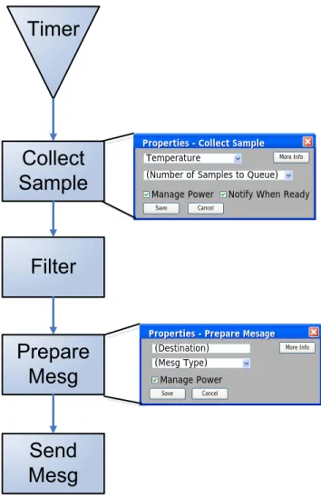
Figure 2: Front End GUI Design Simple Sense Application. A
timer is fired, a sample is taken and a message sent. Shows how dialog boxes will open to parameterize blocks.
Each macro is parameterizable. The parameters depend on the description of the operation and the underlying hard-ware support. For example a macro called “collect sample” is used to gather data from the sensors. Depending on the application a user might want to select the sensor type (tem-perature, acceleration etc..) and how many samples should be taken at once. A flow generator macro that models the timer might allow the user to specify the timer period. By requiring that macros have specific inputs and parameters it is possible to create efficient building blocks.
4.2
Frontend Design
The frontend of the system will be implemented as a graph-ical user interface (GUI) with macros available as a library of icons. The user can click on a macro to bring up a dia-log box containing the macro parameters. Figure 2 presents a conceptual view of the frontend GUI. The application
ex-ample is simple but representative of many monitoring appli-cations. The triangle represents a flow generator component in this case a timer. Once the timer fires a sensor sample is collected an example dialog box is included for the “col-lect sample” macro. Besides the obvious parameters there is one checkbox to enable power management - by providing this checkbox the user has access to an advanced architec-ture feaarchitec-ture. Data is then passed to the filter, a message is prepared and then sent on its way.
In this application example only one of the component outputs were used, but it is possible to create branches in the data flow depending on the result of a data manipulation component. The user is able to create a more complex appli-cation by outlining multiple dataflows. We are currently de-signing architecture support for thread differentiation which would avoid contention between separate flows.
4.3
Backend Design
The backend of the system takes connection information pro-vided from the frontend GUI and pieces together the appro-priate ISRs. For each macro the backend is provided with a set of instruction stubs for tasks such as power management, component configuration, and data transfer. This section ex-plains how routines are created by the backend and how a binary is created.
4.3.1
ISR Routine construction
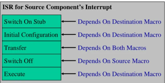
Each connection between macros corresponds to an ISR rou-tine, each ISR routine is made up of a set of Event Processor assembly code stubs. Figure 3 shows how an assembly stubs are tied together to make an ISR routine for either a data ma-nipulation macro or a flow generator macro. The backend is provided with each of the different stub types for every macro it supports.
The ISR routine is called when the interrupt of the source macro is fired. For a data manipulation macro, the first step is to turn on the destination hardware block using the Event Processor’s SWITCHON instruction. The next stub is used to write initial configuration to the hardware block - this of-ten includes any parameters that were specified by the user. The next stub is used to transfer state from the source macro to the destination macro. An example would be a sensor reading, or message packet. Now that state has been trans-fered the source hardware block can be powered off - de-pending on if the user has enabled power management as a parameter. Finally there is an assembly stub that writes the appropriate control words causing the block to begin execut-ing the operation.
Flow generator macros are initialized at system boot and only require a smaller number subset of assembly stubs. Figure 3-(b) presents the routine framework with the actual Event Processor assembly code required to initiate the timer component included as an example. First the timer is pow-ered on with the SWITCHON instruction. Then the configu-ration control words are written to the timer such as specify-ing the timer period. Finally a control word is written to the
ISR for Source Component’s Interrupt Switch On Stub Initial Configuration Transfer Switch Off Execute
Depends On Destination Macro Depends On Destination Macro Depends On Both Macros Depends On Source Macro Depends On Destination Macro
Startup Code
Switch On Stub Initial Configuration Execute/Startup
SWITCHON <TIMER>
WRITEI <Timer Period> <TIMER> WRITEI <ctrl word> <TIMER>
(a) Data Manipulation Macro (b) Flow Generator Macro - Timer
Figure 3: Creating an ISR Routine from Using Assembly Stubs Using the connection map and the a set of assemble stubs for a given
macro the appropriate ISR routine for a given connection is pieced together.
timer causing it to begin counting.
The backend is also responsible for checking the program construction provided by the user for basic errors. These er-rors could include incomplete connections or using too many flow generator units.
4.3.2
Creating the Final Binary
Figure 4 presents a summary of the complete application de-velopment flow. The user lays out the application with the front end interface. The backend is responsible for merging together the macro components to create ISR routines. The assembly code is passed to a hardware specific assembler that resolves labels and generates a complete binary from as-sembly code.
4.4
System Scalability and Extensibility
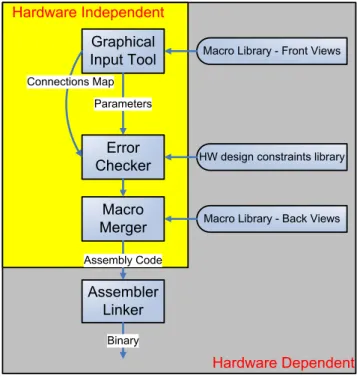
Our design approach with its macro building blocks does not have the flexibility of a high level language such as C. There-fore the programming system architecture allows for macro libraries to be easily added to the system. Figure 5 presents the architecture of the system which is similar to the archi-tecture employed by the CAD tools used in the VLSI com-munity. The frontend and backend are designed to be hard-ware independent and accept library files which are written in a standard format. These libraries could be designed by the hardware vendor or by a third party vendor within the community.
The frontend accepts a frontview of a macro which is a library file that describes the inputs, outputs, and parameters of a block. Documentation could also be attached to a front view. Our application frontend uses this library to display macro icons and dialog boxes to the user. The frontend then provides a standard component map file which describes the connections between the macro blocks. A separate parame-ters file is also passed to the backend.
The error checker unit of the backend accepts a hardware specific constraints file. This file describes any particular limitations of the target hardware platform.
Each macro library frontview has a corresponding
back-view library. This library contains the assembly stubs
de-scribed in section 4.3.1. Using the component map and pa-rameters files the backend will piece together the appropriate ISR routines. The resulting assembly code will be passed to a hardware specific assembler.
5
Conclusion and Future Work
This work presented a design a programming system for sensor network applications which provides ease of use and hardware specific code for the Harvard Event Driven archi-tecture. To achieve our design goals we provide the user with a set of parameterizable macros for typical sensor net-work tasks. The macros are provided to the program through a standard library interface to ensure extensibility and scala-bility.
We are currently in the circuit design phase of our SoC design. The design team is currently time limited due to the tapeout deadline. The final programing system will be com-pleted by the time parts return from IBM.
References
[1] S. D. Glaser. Some real-world applications of wireless sen-sor nodes. In Proc. SPIE Symposium on Smart Structures and
Materials, March 2004.
[2] B. Greenstein, E. Kohler, and D. Estrin. A sensor network ap-plication construction kit (snack). In SenSys, November 2004. [3] M. Hempstead, N. Tripathi, P. Mauro, G.-Y. Wei, and D. Brooks. An ultra low power system architecture for sen-sor network applications. In In The 32nd Annual International
Symposium on Computer Architecture (ISCA), June 2005.
[4] J. Hill, R. Szewczyk, A. Woo, S. Hollar, D. E. Culler, and K. S. J. Pister. System architecture directions for networked sensors. In Architectural Support for Programming Languages
and Operating Systems, pages 93–104, 2000.
[5] S. Madden, M. J. Franklin, J. M. Hellerstein, and W. Hong. TAG: A Tiny AGgregation Service for Ad-Hoc Sensor Net-works. In Proc. the 5th OSDI, December 2002.
[6] Matt Welsh. Macroprogramming Myriads of Sensors.http:
//www.eecs.harvard.edu/˜mdw/proj/mp/.
[7] National Instruments. LabVIEW. http://www.ni.com/ labview/.
[8] M. Petre. Why looking isn’t always seeing: Readership skills and graphical programming. In Communications of the ACM, June 1995.
Figure 4: Application Development Process An application is
first described by connecting components. Then the design is
checked and ISR routines are created by piecing together the macro blocks. Finally the assembly code is layed out, linked and assem-bled in memory.
Figure 5:Programing System Architecture The system is made
up of hardware independent tools which take hardware dependent libraries as inputs. The output is then created by a hardware spe-cific assembler.
[9] V. Shnayder, M. Hempstead, B.-R. Chen, G. W. Allen, and M. Welsh. Simulating the Power Consumption of LargeScale Sensor Network Applications. In Proceedings of the
Sec-ond ACM Conference on Embedded Networked Sensor Systems (SenSys’04), Baltimore, MD, Nov 2004.