Master's Thesis Nr. 47
Design and Implementation of a Fault
Simulation Layer for the Combination
Technique on HPC Systems
Johannes Walter Studiengang: Prüfer: begonnen am: beendet am: CR-Klassifikation: Betreuer: InformatikJun.-Prof. Dr. rer. nat. Dirk Pflüger M.Sc. Mario Heene
13.07.2015 12.01.2016
D.4.1, D.4.4, D.4.5, D.4.7, D.4.8 Institut für Parallele und Verteilte Systeme
Universität Stuttgart Universitätsstraße 38
D - 70569 Stuttgart
Zusammenfassung
In heutigen Supercomputern wird hohe Rechenleistung durch eine große Anzahl an parallel betriebenen Prozessoren erzielt. Mit wachsender Anzahl gleichzeitig be-nutzter Prozessoren erh¨oht sich jedoch die Wahrscheinlichkeit f¨ur das Auftreten von Hardwarefehlern und daraus resultierten Prozessabst¨urzen. Ein weitverbrei-teter Standard zum Austausch von Nachrichten in Netzwerken ist MPI. Aktuelle MPI-Versionen sind nicht fehlertolerant und terminieren im Falle von Fehlern das ganze MPI-Netzwerk. ULFM, eine fehlertolerante Erweiterung f¨ur MPI, ist nicht stabil implementiert und ist auf Supercomputern nicht verf¨ugbar.
In dieser Masterarbeit wird ein Konzept f¨ur einen Fehlersimulator als Zwischen-schicht zwischen MPI und der Anwendung vorgestellt und implementiert, mit des-sen Hilfe Prozessabst¨urze und das Verhalten von ULFM simuliert werden k¨onnen, ohne dass das darunterliegende MPI Netzwerk terminiert wird.
Abstract
In today’s supercomputers, computing power is achieved by using a large amount of parallel executed processors. With growing amount of simultaneously used pro-cessors, the probability of hardware faults with resulting process failures grows as well. A popular standard for exchanging messages in networks is MPI. Current MPI versions are not fault-tolerant and terminate the whole MPI network in case of faults. ULFM, which is a proposed fault-tolerant extension of MPI, is not stable implemented and not available on supercomputers.
In this master’s thesis, a concept of a fault simulator as intermediate layer between MPI and application is introduced and implemented. By means of this fault sim-ulator, process crashes and the behavior of ULFM shall be able to be simulated, without resulting in termination of the underlying MPI network.
Contents
Contents 5
1 Introduction and basics 7
1.1 Introduction . . . 7
1.2 Definitions and terminology . . . 8
1.3 MPI . . . 9
2 Fault tolerance 11 2.1 Fault types . . . 11
2.2 Why fault tolerance? . . . 12
2.3 ULFM . . . 12
2.3.1 New semantics . . . 13
2.3.2 New functions . . . 13
3 Sparse grid combination technique 15 3.1 Handling process failures . . . 17
4 Combi technique framework 19 4.1 Master/worker concept . . . 19
5 Fault simulator 21 5.1 Consistency and first ideas . . . 21
5.2 Concept . . . 23
5.2.1 Blocking send/recv . . . 23
5.2.2 Blocking collective functions . . . 25
5.2.3 Non-blocking collective functions . . . 25
5.2.4 Non-blocking send/recv . . . 26
5.3 Implementation: functions and description . . . 27
5.3.1 Blocking send/recv . . . 28
5.3.3 Non-blocking send/recv . . . 30
5.3.4 Non-blocking collective functions . . . 31
5.3.5 Background broadcast . . . 33
5.3.6 Kill me . . . 36
5.3.7 MPI FINALIZE . . . 37
5.3.8 ULFM functions . . . 39
5.3.9 MPI PROBE . . . 41
5.3.10 MPI COMM FREE and free outstanding non-blocking oper-ations . . . 41
5.4 Silent faults . . . 49
5.5 Other approaches . . . 51
5.5.1 One master coordinates all failures . . . 51
5.5.2 Use topology of Combigrid-Framework . . . 51
5.5.3 Replace all blocking operations with their non-blocking versions 53 5.5.4 Using remote procedure call . . . 53
5.5.5 Spawning processes or threads . . . 54
5.6 Using the fault simulator . . . 55
6 Integration into Combigrid and tests 57 6.1 Fault tolerant master/worker . . . 57
6.2 Tests . . . 61
6.2.1 Performance tests . . . 61
6.2.2 Stability tests . . . 62
6.2.3 Functional tests . . . 62
6.2.4 Test results . . . 63
6.3 Conclusion and outlook . . . 67
A Test results (full) . . . 69
A.1 Performance Tests . . . 69
List of Figures 89 List of Figures . . . 91
1 Introduction and basics
1.1 Introduction
MPI (section 1.3) is used in supercomputers to transfer messages and access dis-tributed stored data. With growing network size the probability of process failures due to hardware malfunction is rising steadily. The current MPI standard does not support handling process faults. After a failure is detected, the MPI network is terminated. A proposed standard ULFM (section 2.3), an addition to the current MPI standard, offers fault tolerance. A prototype implementation of ULFM exists (implemented in Open MPI), but supercomputers mostly use custom implementa-tions of MPI and thus ULFM is not available. There are numerical methods like
Figure 1.1: Fault simulator as layer between MPI and the application.
the combination technique (chapter 3) , that can handle process faults. To be able to run and test these methods, a fault simulator is needed, providing the ability to simulate process failures.
In this thesis we discuss and create a fault simulator (chapter 5) as a layer between the regular MPI implementation and the application. The simulator shall support all important MPI functions used by the combi technique framework (chapter 4), like for example blocking and non-blocking point-to-point operations, or specific blocking collective operations. Also for the sake of realism the fault simulator should use as least resources as possible. In chapter 6.2 we define and execute some tests and discuss the test results. For the implementation the programming language C++ 11 is used. The C++ code located on the CD-R on the last page is part of this thesis. While the implementation is theoretically portable and could
be used on multiple operating systems, it is only tested on current Linux distri-butions, because Linux is widely used for high performance computing. The MPI environments used for testing the fault simulator were MPICH, Open MPI and the implementation on Hazel Hen.
In this thesis the information about MPI and its functions is directly taken from the MPI standard specification [MPI15], whereas the information regarding ULFM is taken from the proposed ULFM standard [ULF].
1.2 Definitions and terminology
In this section we define a few notions we use frequently. At first let’s take a look at the definition of a deadlock according to [Tan08].
Definition 1.2.1 (Deadlock)
A deadlock is a state in a distributed system, where a set of processes wait for an event to occur, that can only be triggered by a process in the same set.
For example if we have two processes, p1 and p2. We have a deadlock if p1 waits
for a message from p2, whilep2 waits for a message from p1. In our fault layer we
have to be really careful with deadlocks.
In our fault layer we use various distributed algorithms and protocols. We can think of them as a ’distributed function’, where we input some values and expect a specific output. The following definitions of strong and weak consistency are based on [KRS+13].
Definition 1.2.2 (Strong consistency)
A distributed algorithm is strong consistent, if it behaves as if it was executed locally and any intermediate (inconsistent) steps are not visible to the application.
While strong consistency is very desirable, it is not possible to achieve it in every situation. Additionally it comes with a possible high overhead, because processes have to be synchronized in order to guarantee only consistent states.
Definition 1.2.3 (Weak consistency)
A distributed algorithm is weak consistent if it is possible to read inconsistent values within its execution, but eventually a consistent state is achieved.
An inconsistent state is for example if one process has access to the finished results of the algorithm, while another can access unfinished values.
The definitions of fault, failure and fault tolerance according to [IEE90].
Definition 1.2.4 ((Hardware) fault)
A defect in a hardware device or component; for example, a short circuit or broken wire.
1.3 MPI Definition 1.2.5 (Failure)
The inability of a system or component to perform its required functions within specified performance requirements.
A fault might (but doesn’t have to) lead to a failure. The cause of a failure might be as well hardware faults as also software faults (like software bugs).
Definition 1.2.6 (Fault tolerance)
The ability of a system or component to continue normal operation despite the presence of hardware or software faults.
1.3 MPI
MPI (Message Passing Interface, [MPI15]) is a standard for a portable message-passing interface in a network. Multiple implementations of MPI are available, like Open MPI or MPICH and its many derivatives (from vendors like IBM, Intel or Microsoft).
The current version of MPI is 3.1 (released 2015). It gives support for blocking and non-blocking point-to-point operations (such as MPI SEND and the non-blocking version MPI ISEND) and collective operations (for example MPI BCAST and the non-blocking version MPI IBCAST). Additionally MPI gives a standardized inter-face to access files, handle process topologies, dynamically spawn processes and more. Explicitly NOT included is support for interrupts or remote procedure calls. While non-blocking point-to-point operations are included in the standard since MPI 1.0 (released 1994), non-blocking collective operations are included only since MPI 3.0 (released 2012) and thus possibly not included in all today used MPI im-plementations, especially regarding custom implementations in high performance computers. We therefore try to avoid using non-blocking collectives in our fault layer and use custom versions of MPI IBCAST and MPI IREDUCE (also see sec-tion 5.3.5.1).
2 Fault tolerance
(Also see chapter 8.3 in [MPI15])
The current MPI standard does not support handling process faults (especially process failures). If an error is detected by the MPI network, the MPI network will be aborted similar to executing MPI ABORT and the execution state from this point will be undefined. It is possible to change the MPI error handler from MPI ERRORS ARE FATAL to another handler like MPI ERRORS RETURN, which leads to the network not being terminated immediately after an error, but the state is still undefined and calling MPI functions after an error occurred might be not possible (depending on the implementation).
2.1 Fault types
Before we begin discussing an approach to simulate faults we first need to define, what is considered faulty behavior and which types of faults we intend to simulate. Using the classifications and definitions from [KKL05], we have four types of fault models as depicted in Figure 2.1. Fail-Stop is a very common used model, where a process either works as specified or stops its execution completely. This might be detected by other processes. Fail-Stutter includes (detectable) hardware corrup-tion like memory bit flips or performance loss, while the process might still continue its operation. Silent Fail-Stutter adds undetectable malfunction, like undetectable memory bit flips or performance loss due to hardware malfunction. Byzantine means the behavior is totally unspecified and anything could happen, including (detectable and undetectable) corrupted data, freezes, undetectable random mes-sage initiation in the network (concerning MPI), etc.
Byzantine is the most undesirable kind of faulty behavior, because although a faulty process acts totally undefined and unpredictable, from the outside it might not be detectable and might look like the process performs just like the other processes. For our fault simulator, we use the Fail-Stop model, meaning a process either works as expected without any faults, or the process crashes completely. In our fault simulator if a process is dead, it stays dead until the application is terminated by calling MPI FINALIZE or MPI ABORT. Additionally we briefly discuss Silent faults in section 5.4 and implement the possibility to simulate random bit flips.
Figure 2.1: Different types of faults / fault models according to [KKL05].
2.2 Why fault tolerance?
We begin with a simple fictional example. Assume we have a supercomputer with 5000 nodes and the lifetime of a node (that means the time until it fails) is exponen-tial distributed with an expected lifetime of λ1 = 1000 days. By further assuming, the lifetimes are stochastically independent, we can calculate the expected value of the event ’any node dies’:
E({any node dies}) =
1 Σ5000 k=1 1 1000 = 1000 5000 = 1 5 (in days).
As you can see, while with one node a failure is expected after years, with 5000 nodes a failure is to be expected only after a few hours. Without any fault tolerance this would mean, the whole network fails, the failed component has to be repaired and the network has to be restarted every few hours.
One possibility to counteract this problem is to install redundant and fault tolerant components to reduce the risk of hardware failures or at least to reduce the impact. Another possibility is to make the software itself fault tolerant, this means for example instead of restarting the network after a failure is detected, the failed node is just excluded and the current operation is continued using only the other nodes.
2.3 ULFM
ULFM (User Level Fault Mitigation) [ULF] is a proposal of a fault tolerant MPI specification based on the (back then) upcoming MPI version 3.1. The proposal
2.3 ULFM
is created by the MPI Forum’s Fault Tolerance working group 1. The idea is that instead of terminating the whole MPI network after an error is detected, the user has the possibility to catch errors and react to them without having to restart the MPI network.
2.3.1 New semantics
If no process failures occur, ULFM behaves just like the regular MPI. In case of a process failure, there are new MPI error codes that can be returned by point-to-point or collective operations to inform the application of a present failed process. MPI ERR PROC PENDING is returned for a non-blocking receive operation if its source is MPI ANY SOURCE and a possible matching sending process for the receive operation has failed.
MPI ERR PROC FAILED is returned in the general case if an operation cannot be successfully completed because of a present process failure.
If a process failure is detected, the application can create new communicators excluding the failed processes and continue the execution. Process faults are only propagated to processes calling MPI operations involving the failed process. If for example a process wants to send a message to a failed process using MPI SEND, only this process is notified of the failure.
In case the other processes in the communicator have to be informed about the dead process, the communicator can be revoked. As a result eventually all point-to-point and collective MPI operations in the revoked communicator return the error MPI ERR REVOKED.
2.3.2 New functions
We take a brief look at the ULFM functions implemented in our fault layer. For a complete and more detailed overview please take a look at the proposed ULFM standard [ULF].
intMPI Comm revoke(MPI Comm comm)
Revokes a communicator and notifies all processes in the communicator. Eventually all operations (except MPI COMM SHRINK and MPI COMM AGREE) using the revoked communicator will be completed and return MPI ERR REVOKED.
intMPI Comm shrink(MPI Comm comm, MPI Comm* newcomm)
If process failures are detected, the dead processes can be excluded using this function. The newly created communicator ’newcomm’ will contain all processes from ’comm’ excluding the detected dead processes until this point.
intMPI Comm failure ack(MPI Comm comm)
This function can be used to acknowledge process failures. After this it is possible to receive a point-to-point message with source MPI ANY SOURCE (the appli-cation is responsible to make sure the sending process is not dead). Additionally the function MPI COMM FAILURE GET ACKED can be called to get a group containing all acknowledged dead processes in the communicator.
intMPI Comm failure get acked(MPI Comm comm, MPI Group* failedgrp)
Returns a group containing all acknowledged dead processes. Before calling this function, MPI COMM FAILURE ACK has to be called first or otherwise the group will be empty.
intMPI Comm agree(MPI Comm comm,int* flag)
If any process failure occurs in ’comm’, this collective function will return the error MPI ERR PROC FAILED at all alive processes in the communicator. If no process is dead, the function will return MPI SUCCESS at all processes in the communicator.
Additionally this function performs a bitwise ’AND’ operation with the values of flag from all participating alive processes. That means flag will be set to 0 at all processes if it is 0 at any alive process participating and it will stay 1 if flag is 1 at all alive processes.
3 Sparse grid combination technique
This chapter is based on [HKH+15] and [HHJP].
In section 2.2 we have discussed, why fault tolerance is important. With ULFM we have a standard that makes MPI fault tolerant. While ULFM offers the ability to detect and treat process faults without having to terminate the MPI network, the application has to be specifically programmed to react appropriately to dead processes.
In this chapter we have a brief look at the sparse grid combination technique, a numerical method that has the ability to efficiently handle detected process faults and thus gain significant advantage by using ULFM compared to restarting the whole computation or using checkpoint-restart.
The basic idea is for the discretization of ad-dimensional space Ω = [0,1]d, instead of using a uniform full grid Ωn with mesh width hn= 2−nrequiring O(2nd) points,
an approximation using a significantly lower amount of points is used, by increasing the approximation error only insignificantly. The approximation grid is created by linear combining smaller anisotropic grids Ωl with mesh-width hlk := 2
−lk for the
multi-index so called level-vectorl = [l1, l2, ..., ld].
Figure 3.1: Full grid Ω[4,4] (blue) gets approximated by combining the green grids
Letfn(x) be the d-dimensional solution of a problem on the grid Ωn. The idea is
to approximate the solution by a weighted sum of solutions from smaller grids
fn(x)≈fn(c)(x) =
X
l∈L
clfl(x)
where L is a set of level vectors of grids Ωl used for the combination and ci are
appropriate weights. The special case
fn(c)(x) = d−1 X q=0 (−1)q d−1 q ! X l∈Ln,q fl(x)
is then the classic sparse grid combination technique with
Ln,q ={l ∈Nd:|l|1 =|lmin|1 +τ −q:lmin ≤l ≤n},
wherelmin =n−τ1, τ ∈N0, so that lmin ≥1.
3.1 Handling process failures
3.1 Handling process failures
If a process fails during calculation, instead of completely restarting the compu-tation of the corresponding grid on another process, a failed calculation can be replaced by changing the weights of the combination technique and calculating smaller (and faster to calculate) problems, while increasing the approximation er-ror only insignificantly. The choice of the weights is important, because bad grid replacements might increase the approximation error noticeable or cause unneces-sary computation cost. For more information see for example [HKH+15].
Figure 3.3: A possible combination of the last example with failed calculation of grid Ω[2,3]. Only the solution of grid Ω[1,2] has to be calculated instead
4 Combi technique framework
The main purpose of this thesis is to be able to use the fault simulator in the combi technique framework. In this chapter we have a brief look at the construction of the framework.
4.1 Master/worker concept
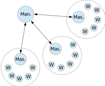
In the framework we have numerous working groups consisting of a specific amount of worker processes and one master process. Additionally we have one single man-ager process, communicating with the master processes and sending them new jobs to compute (see Figure 4.1). The master processes receive the jobs and forward them to their worker processes. After the job computation is completed, the master process contacts the manager process and asks about the next job. The workers do not communicate with other processes outside their working group. If information needs to be exchanged with other groups, this is done merely by communication between the master processes and the manager process.
Figure 4.1: The Manager process distributes jobs to the master processes of each group. The master processes forward the jobs to their workers.
5 Fault simulator
5.1 Consistency and first ideas
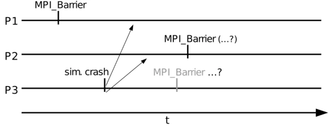
While creating and developing the fault simulator, some initial approaches lead to problems concerning consistency and deadlocks. To have a better understanding about the thought process of creating the fault simulator, we take a look at an approach with possible deadlock (see Figure 5.1 as an initial example). The first
Figure 5.1: Process 3 dies, while process 1 already initiated MPI Barrier. Possible dead lock if not treated right.
idea for blocking collectives was for every process to immediately execute blocking collectives after called by the application. The root process of every communicator would then have to inform possible dead processes about recently started blocking collectives, ”command” them to participate in the blocking collective and unblock all processes. This approach was quite promising regarding performance, because while no process was dead, no further communication was necessary and the per-formance would have been equal to the regular MPI.
However, the root process had to know about all dead processes and send a command-message before its own blocking collective was executed, forcing all pro-cesses to send a message to root prior to any blocking collective operation. Fur-thermore some special cases like the example in Figure 5.2 lead to a deadlock. To be able to avoid this deadlock, a more complex treatment of process failures was required. This ultimately lead to the implemented version, where all process faults are synchronized before any ”real” blocking MPI collective is executed.
(a) Two communicators with dead processes d1 and d2 being member of both commu-nicators.
(b) Processes of both communicators start a MPI BCAST operation (indicated by the border). Note that the root processes technically start the barrier only after they sent their last point-to-point message (af-ter (d) ).
(c) Both root processes begin to com-mand the dead processes to execute an MPI BARRIER.
(d) d1 begins a barrier in comm1, d2 begins a barrier in comm2. Further command mes-sages are not received. Deadlock.
5.2 Concept
5.2 Concept
In this chapter we present simple ideas for a layer between the application and MPI to be able to support simulated process faults. In case of no present simu-lated process faults, we want MPI to behave as if there was no layer between the application and MPI. To distinct between MPI functions and the corresponding functions in the simulated fault layer, we name the layer functions with the prefix SIM . In this section we first take a look at the basic ideas and in the next section we describe the actual implementation (more detailed).
5.2.1 Blocking send/recv
Blocking functions are most straightforward. In case we have no simulated process fault, the design of MPI requires that an MPI SEND has a matching MPI RECV on another node in the communicator (as well as any MPI RECV has a matching MPI SEND) - assuming the application itself is written correctly.
For a first simple approach we don’t take into account that MPI SEND and MPI RECV might interact with other MPI functions like MPI PROBE.
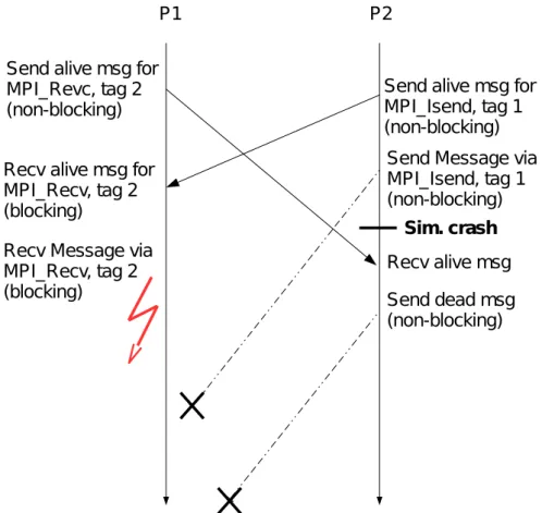
Send alive msg
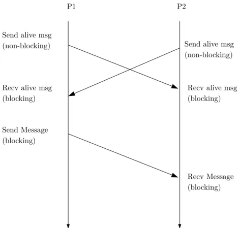
(non-blocking) Send alive msg (non-blocking) Recv alive msg (blocking) Recv alive msg (blocking) Send Message (blocking) Recv Message (blocking) P1 P2
Case 1: A process initiates a SIM MPI SEND to an alive process in the communicator
(See Figure 5.3) After initiating SIM MPI SEND, process 1 sends an alive-message to process 2 and waits for an alive-message from process 2. Process 2 does the same the other way around after initiating the matching SIM MPI RECV. After both processes received the alive-message, the actual MPI SEND and MPI RECV are executed.
Case 2: A process initiates a SIM MPI SEND to a dead process in the communicator
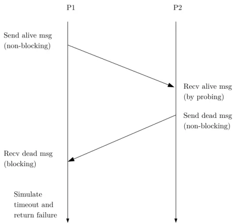
(See Figure 5.4) Process 1 sends an alive-message to process 2 and waits for its response. Process 2 responds with a dead-message and process 1 returns the MPI call with the error MPI ERR PROC FAILED.
Send alive msg (non-blocking) Send dead msg (non-blocking) Recv dead msg (blocking) Recv alive msg (by probing) Simulate timeout and return failure P1 P2
Figure 5.4: Blocking send to a dead process (Case 2).
Case 3: A process initiates a SIM MPI RECV to receive a message from a dead process
5.2 Concept Case 4: A process initiates a SIM MPI RECV to receive a message from any process (MPI ANY SOURCE) in a communicator with no dead processes
In this case we can’t just ”synchronize” with another process to know about its alive status. Instead we probe for messages. If an incoming message is detected by probe, receive it by calling MPI RECV and its return code is returned by SIM MPI RECV.
Case 5: A process initiates a SIM MPI RECV to receive a message from any process (MPI ANY SOURCE) in a communicator with one or more dead processes
The procedure is the same as in Case 4, but instead of receiving the message, we get notified of a present dead process in the communicator, stop probing for incoming messages and return the error MPI ERR PROC FAILED.
5.2.2 Blocking collective functions
As with the blocking send/recv we are guaranteed, that a blocking collective oper-ation is called at every (alive) node in a communicator.
We use this fact and exchange the information through the whole communicator, which processes are currently dead, right before an actual collective MPI operation should be executed. If there are one or more dead processes, the collective operation is not executed and the call is returned with the error MPI ERR PROC FAILED. If all processes are alive, the intended collective MPI operation is executed and the return code of this operation is returned to the application.
For our synchronization of how many processes are dead right before the blocking operation should begin, we require the synchronization protocol to be strong con-sistent. The reason for this is, because we intend to execute the actual blocking MPI operation and a collective operation cannot be canceled in MPI (especially a blocking one), we require either none or all processes in the communicator to participate.
5.2.3 Non-blocking collective functions
Non-blocking collectives are sparsely more complicated. While the first idea might be to immediately begin a communication and cancel it if a participating process is dead, this is unfortunately not possible, because non-blocking collectives cannot be canceled with MPI CANCEL.
A non-blocking MPI operation call has to return immediately, so we cannot syn-chronize our knowledge about present dead processes prior to the non-blocking call. We therefore immediately execute any non-blocking collective function after called by the application and check for dead processes later within a completion function.
If a process fault is detected in a completion call and the detected dead process never called the corresponding non-blocking collective function, it is assumed that the collective operation is never going to be completed (that is true especially for functions like MPI IBARRIER - where every single rank in the communicator has to participate before the call can be completed). The MPI request is then completed by MPI REQUEST FREE and the completion function returns the error MPI ERR PROC FAILED.
Because the ”checking” for dead processes is done in a completion operation and the collective operation is called even if one or more processes are dead in the communication, we only need our synchronization protocol to be weak consistent. That means eventually all processes know about every present dead process in the communicator.
5.2.4 Non-blocking send/recv
We have the same situation as with non-blocking collectives. Unlike the blocking version we cannot ”check”, if a process is alive or dead before a send or receive operation is started. A non-blocking send/recv has to return immediately.
Because of that, our layer also forwards a message by MPI ISEND or initiates a receive by MPI IRECV immediately after function call. We use the fact that a non-blocking operation has to be completed by either MPI TEST, MPI WAIT or MPI REQUEST FREE. The ”alive-checking” is done when the application calls such a MPI completion function.
Essentially the non-blocking send and receive operations use the same approach as the one from non-blocking collectives.
5.3 Implementation: functions and description
5.3 Implementation: functions and description
For the implementation we want the simulated-faults-layer to have the least impact on the application as possible. On the one hand a programmer should only have to include the header files ’MPI-FT.h’ and ’MPI-FT redefine.h’ instead of ’MPI.h’ to enable the fault simulator. On the other hand (as already mentioned) if no process is killed by calling Sim FT kill me and no ULFM functions are used, the application shall behave as if no fault simulator was active.
Redefine MPI functions
In the layer we have customized versions of MPI functions using MPI communi-cators or MPI requests. It is unreasonable for a programmer having to replace all MPI functions in an application with the layer versions. For that reason by includ-ing ’MPI-FT redefine.h’, all important MPI function names are replaced by usinclud-ing the preprocessor directive ’#define’ (e.g. ’#define MPI Send Sim FT MPI Send’). The programmer doesn’t have to worry about anything and continues using the MPI functions as if there was no layer.
Use custom versions of MPI Comm and MPI Request
In our fault layer, for a MPI Comm object we need to have access to much more in-formation than ”only” the MPI Comm object. In our header ’MPI-FT.h’, we define a C++ struct Sim FT Comm struct containing variables like the real MPI Comm object used by the application, some copies of the MPI Comm object (created with MPI COMM DUP) used by our fault layer, some variables needed for a custom tree structure (also see section 5.3.5.1), a list of all currently detected dead processes in the communicator and much more.
We want our custom MPI communicator to behave like the real MPI Comm, that means for example it should not contain information directly. Instead it should behave like a pointer (similar to the real MPI Comm) and all information is stored at the pointed location. Our custom MPI Comm object (Sim FT MPI Comm) is therefore simply a pointer to a Sim FT Comm struct, which replaces the native MPI Comm using a simple preprocessor define.
typedefSim FT Comm struct* Sim FT Comm;
#defineMPI Comm Sim FT Comm
If now the user declares a new MPI communicator object in the application, in-stead a pointer to our custom communicator struct is declared. On creation of a new communicator, the struct object is dynamically created using C++ new and the custom MPI communicator points to this newly created object. If a communi-cator is deleted by MPI COMM FREE, the dynamically created struct is deleted using C++ delete and the pointer is set to nullptr (which is in our layer equal to MPI COMM NULL: if the user compares a nullptr custom comm object with MPI COMM NULL using ==, it will return true).
Store currently active communicators
informa-tion, in which communicators a specific process is currently active. For that we have a global available std::set object containing pointers to all custom commu-nicator objects the local process is active. Every time a new commucommu-nicator is created, for example by calling MPI COMM SPLIT, the newly created communi-cator ’newcomm’ is added to this set. If a communicommuni-cator is destroyed by calling MPI COMM FREE, the reference to the communicator object is deleted from the active list. This is required for example if a process calls Sim FT kill me and has to iterate through all active communicators.
5.3.1 Blocking send/recv
While it is true that MPI guarantees FIFO (first in first out) delivery of mes-sages between two processes, this only applies if the communicator and the tag are the same (1). Additionally it is possible to receive a message sent by the non-blocking MPI ISEND with the non-blocking MPI RECV (and the other way around with MPI IRECV and MPI SEND) (2). For the implementation we have to take into account that one process might have multiple outstanding incoming messages simultaneously, especially with different tags (3).
We don’t want alive-messages to interfere with normal MPI communication from the application. Combining the facts (1) to (3), for sending and receiving the alive-message, we cannot use the same tag for all alive-messages because with multiple outstanding messages to receive we wouldn’t know which alive-message belongs to which MPI message, possibly leading to a deadlock (see Figure 5.5 for a simple example). A solution for this problem is to duplicate the communicator c comm to c comm copy p2p and use the copy merely to send alive-messages. This way point-to-point alive-messages are delivered in the same order as their corresponding ”real” MPI messages (note this problem only occurs because MPI RECV can receive from MPI ISEND; if blocked and non-blocked messages were separated, this would not be necessary).
5.3.2 Blocking collective functions
For the implementation we use an operation similar to MPI IALLREDUCE to synchronize dead processes across the communicator prior to any ”real” MPI col-lective. The call ’Sim FT Check dead processes’ consists of a reduce, combined with a broadcast. We have two possible cases (note however there is an additional case if the communicator is revoked, this will be discussed in section 5.3.8.3).
Case 1: No process in the communicator is dead
The simulated fault layer for blocking collectives consists of two steps.
Step 1: All ranks in the communicator initiate a reduce operation with the message ’0’ to the root rank of the communicator.
5.3 Implementation: functions and description
Figure 5.5: Blocking and non-blocking point-to-point can be mixed in MPI. Pos-sible deadlock if alive-messages are transfered without tag. Example where P1 receives an alive-message belonging to an MPI ISEND on another tag and starts receiving a non-existent message.
Step 2: Root rank broadcasts the information ’no processes are dead’ to all other ranks in the communicator.
Step 3: The collective MPI function is executed at all ranks in the communicator.
Case 2: One or more processes in the communicator are dead
Step 0: After a process calls Sim FT kill me, it immediately sends a notification of its dead status to the root process of every communicator the dead process is currently active.
Step 1: All ranks in the communicator reduce the count of current dead processes in the communicator to the root rank of the communicator.
Step 2: Root waits for incoming dead messages until the messages from all dead processes are received.
Step 3: Root rank broadcasts the count of dead processes and a list including the ranks of all dead processes to all members of the communicator.
Step 4: Every alive process returns the MPI call with error MPI ERR PROC FAILED and adds the dead processes to a local list of dead processes.
Step 1: Reduce Step 2: Broadcast
Figure 5.6: Collective operation without dead processes (Case 1).
Step 1: Reduce Step 2: Broadcast
Figure 5.7: Collective operation with 3 dead processes (Case 2).
5.3.3 Non-blocking send/recv
As mentioned above, any layer functions with the intention to check for present dead processes regarding non-blocking MPI operations can only be weak consis-tent to preserve the non-blocking behavior of these MPI operations. We have two possible cases. For readability we assume for Case 1 and Case 2 the local called operation is MPI ISEND. For MPI IRECV the procedure is similar with switched roles of MPI ISEND and MPI IRECV. The special Case 3 is specifically for MPI IRECV.
5.3 Implementation: functions and description Case 1: The point-to-point partner node is alive
Step 1: After calling SIM FT MPI ISEND, an alive-message is sent non-blocking to dest using the tag of the message and using communicator c comm copy p2p. Immediately after sending, the actual non-blocking message operation MPI ISEND is called using the parameters of SIM FT MPI ISEND and communicator c comm. Step 2: dest calls SIM FT MPI IRECV, sends an alive-message and calls MPI IRECV (similar to Step 1).
Step 3: After calling a completion function, the alive-message of dest is received and the call is completed.
Case 2: The point-to-point partner node is dead
Step 0: After the dead process calls Sim FT kill me, a dead-message is sent to the root of every communicator. Root initiates a broadcast containing a list of all recently detected dead processes, including dest.
Step 1: (same as Step 1 of Case 1).
Step 2: The dead process (dest) receives the alive-message and ignores the message. The alive process receives the broadcast from root and adds the partner node to a local list of dead processes. Any upcoming completion operation (MPI TEST, MPI WAIT,...) concerning a message to or from the partner node is returned with the error MPI ERR PROC FAILED.
Step 3: The alive process sends an ”command message” to the dead one, ordering the dead process to receive the outstanding MPI ISEND by calling a matching MPI IRECV. The purpose of this message is to complete the actual sent message and free resources.
Case 3: MPI IRECV with source MPI ANY SOURCE and a present dead process in the communicator
In this case, after calling a completion operation, the function is returned with the error MPI ERR PROC FAILED PENDING.
5.3.4 Non-blocking collective functions
Collective operations are guaranteed to be executed in the same order at all ranks in the communicator [MPI15, Example 5.30]. That is for example in a communicator with two processes (rank 0 and rank 1) if rank 0 first calls an MPI IBARRIER, then an MPI BARRIER and finally an MPI IBCAST, rank 1 has to execute these functions in the exact same order.
By design of our fault simulator, we are guaranteed that a blocking collective operation is only executed if no processes are dead. It is therefore not possible to have a blocking collective active only on a subset of a communicator.
In our customized communicator object, we store for each process locally its re-cently executed non-blocking collective operations since the last blocking collective
was executed.
We use a list containing objects with the information, which non-blocking collective was executed and what its parameters were, for example the operations’ root rank, how big the collective message was (e.g. in case of MPI IBCAST) or which opera-tion was used (for MPI IALLREDUCE or MPI IREDUCE). This object might be extended to support tracking more non-blocking collective operations.
The purpose of this list is to be able to complete outstanding non-blocking collec-tives on the one hand and to free blocked processes waiting for the completion of a non-blocking collective that is never going to be completed because a dead process never executed the corresponding non-blocking collective operation on the other hand. The actual messages of these operations are not stored, because in order to free an operation it is sufficient to send a dummy message with arbitrary values -only the size of the message is important.
Let’s take a look at how non-blocking collective functions are executed in the fault simulator, beginning with the call of the function and ending with the completion of the collective operation. For readability we call the non-blocking collective function MPI ICOLLECTIVE.
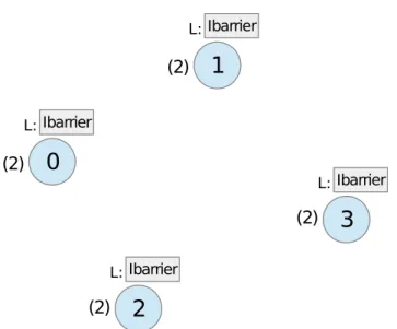
We have three possible cases regarding the execution of non-blocking collective functions, all beginning with the same Step 0:
Step 0: After calling SIM FT MPI ICOLLECTIVE, the corresponding collective MPI ICOLLECTIVE is executed immediately and its parameters are added to the local list of recent non-blocking collectives (as mentioned at the beginning of this section). The return value of MPI ICOLLECTIVE is then returned by SIM FT MPI ICOLLECTIVE. Note that no checking for failed processes is done here in order to be consistent with the proposed ULFM standard.
In the following let’s assume the collective operation is to be completed with MPI TEST. For simplicity we say ’NBC’ short for ’non-blocking collective’.
Case 1: No process in the communicator is dead at the time of comple-tion
Step 1: After the completion function SIM FT MPI TEST is called, the fault simu-lator calls MPI TEST and returns its return values. If the operation was completed, the custom request object is deleted using C++ delete and the request pointer is set to nullptr.
5.3 Implementation: functions and description Case 2: One or more processes in the communicator are dead at the time of completion and the NBC count of at least one dead process is lower than the local NBC count
Step 1: Immediately after a process goes ”dead” by calling Sim FT kill me, it sends a message to the root rank of each communicator containing the current size of its list of recent non-blocking collective operations.
Step 2: Root broadcasts this count to all ranks in the communicator if no count has been broadcasted yet or the count is lower than the count from the last broadcast. Step 3: The current process receives the broadcast and compares the NBC count from the broadcast with the local NBC count. Because the local count is higher than the one from the dead process, it assumes the dead process never participated in the non-blocking collective and thus the operation will not be completed. The completion function is returned with the error MPI ERR PROC FAILED.
Step 4: After calling MPI COMM FREE on the current communicator, all out-standing non-blocking collectives are completed at all processes in the communi-cator, including the dead ones (also see section 5.3.10 for more details about how the collective operations are completed).
Case 3: The communicator is revoked
Step 1: If the communicator is revoked, we have to assume that the non-blocking collective is never executed on one or more other processes in the communicator. As specified in the ULFM standard, the SIM FT MPI ICOLLECTIVE function call is then returned with the error MPI ERR COMM REVOKED and the collective operation is not executed.
5.3.5 Background broadcast
For our layer it is important to be able to send messages in the background through the whole communicator. One way to do this would be directly sending a non-blocking point-to-point message to all other ranks in the communicator. Whereas for a small communicator this approach would be totally fine, bigger communica-tors would lead to performance issues because this basic approach doesn’t scale. As mentioned in chapter 1.3, we use two different scaling approaches to send mes-sages in the background. One using non-blocking collective functions and the other using a custom implementation of blocking collectives only consisting of non-blocking point-to-point operations.
5.3.5.1 Approach without non-blocking collectives
To be able to run our fault simulation layer with MPI implementations not (fully) supporting non-blocking collectives, we use a custom version of non-blocking MPI IREDUCE and MPI IBCAST only consisting of non-blocking point-to-point mes-sages.
When a communicator is first initialized, for example after calling MPI COMM SPLIT, we have to initialize our custom communicator in the layer by calling Sim FT Initialize new comm. On initialization we create a very simple tree topol-ogy (described below) and saving locally for every process in the communicator object, which ranks its successors are and which rank its predecessor is. The tree uses the root as specified in the communicator object (default rank 0 in the com-municator).
Having a tree topology, we can use this topology to create our custom non-blocking collectives. Note that dead processes use slightly different versions of these collec-tive operations than alive processes, because dead processes initiate the operations in advance and alive processes only initiate operations when a collective MPI op-eration is to be executed.
Tree topology
This very basic approach of creating a tree topology does not take into account the topology of the underlying network. Assume root of the tree has id 0 and every node in the tree shall have two (or less) children. Then the successors of root would be rank 1 and 2. Rank 1 would have the successors 3 and 4, while rank 2 would have the successors rank 5 and 6, etc.
Figure 5.8: Simple tree topology with 8 nodes and max. 2 child nodes.
The calculation of the predecessor and the successors is very simple. The calcula-tion of the successors is described in Algorithm 1.
Algorithm 1 Calculate successors
1: procedure Bcast Get Successors(root, id, tree size, Successor Count)
2: for i←0,Successor Count−1do
3: k ←NormalizeId(id,root) . Shift process ids s.th. root has rank 0.
4: k ←ConvertId(k, tree size) .Make sure 0 ≤k < tree size
5: j ←k∗Successor Count + i + 1
6: j ←DeNormalizeId(j) . Revert the shift from the beginning 7: j ←ConvertId(j, tree size) . Make sure 0≤j < tree size
8: Add j to the vector of successors from id
9: end for
10: end procedure
In the algorithm, tree size denotes the number of ranks in the communicator. The assignment is unique, so the inversion (calculation of the predecessor) is just as
5.3 Implementation: functions and description
simple: assuming the id is already normalized, the predecessor is calculated by the following formula
PredecessorID = id−1−(id−1) mod Successor Count Successor Count
which has to be denormalized afterwards.
These functions are called every time a new communicator is created. The succes-sors and predecessucces-sors for every process in the communicator are then permanently stored in the custom communicator object.
Custom IBCAST
The custom non-blocking broadcast can send messages via specific tags using a special copy of the regular communicator to not interfere with MPI communication from the application. Every process in the communicator has to frequently call the function ’Sim FT Perform background operations’ to forward incoming broadcast messages. The custom broadcast waits for a non-blocking point-to-point-message from the current process’ predecessor. After receiving the message, it forwards the message to all successors (”child nodes”) in the tree by sending a non-blocking point-to-point-message using the same tag.
Custom IREDUCE
The custom ireduce is a little bit more complicated because we cannot receive a message and forward it in the same step. We need to save the information, how many successors have already sent a message and perform a reduce operation for every received message. After all successor messages are received, the reduced message is then sent to the predecessor via a non-blocking point-to-point-message. There are two slightly different versions of the custom non-blocking reduce. One version is used by alive processes, it behaves like a blocking reduce with one im-portant difference, that while waiting for incoming messages, our layer function Sim FT perform background operations is called continuously.
The other version is used by dead processes. This version has to be non-blocking, because a dead process iterates through many different communicators and has to maintain multiple custom non-blocking reduce operations simultaneously. For this reason, the current reduce message and the information, which successor message is already received, is stored inside the custom communicator object. If a new successor message is received, the stored message gets ”merged” together with the received message by a reduce operation.
5.3.5.2 Approach using non-blocking collectives
Note that due to compatibility issues, this approach is not implemented. Never-theless we take a look at the basic idea because of the possible performance boost.
While the custom implementation of a non-blocking broadcast is function-wise to-tally fine, the tree created does not take the topology of the network into account. A successor of the custom topology could therefore be far away in the network, leading to high delay and low transfer speed, while there could be multiple nodes locally on the same machine with almost zero delay and instant data transfer. Additionally a message in the custom broadcast is only forwarded if the succes-sor received the message and calls the custom broadcast function, where a MPI-internal non-blocking broadcast could be optimized to forward a message through the communicator even if a broadcast function is not called on all nodes in the communicator.
Now returning to the MPI non-blocking collective functions. The idea is very simple: in our custom communicator object, we have defined a root rank and a MPI REQUEST object for every background broadcast we intend to use. On the initialization of a communicator object, each rank in the communicator except root begins a MPI IBCAST. For example if the background message is to be ’comm is revoked’ and the used communicator object is ’comm’, the call looks like
MPI Ibcast(0, 0, MPI INT, comm->Root Rank,
comm->c comm copy collective, comm->Revoke Request);
If now the communicator is to be revoked, root also calls this function and after calling a completion function, the non-blocking broadcast will be executed at all ranks. If a process wants to know if the communicator is revoked, it only has to check with MPI TEST, if the broadcast is completed (meaning, the buffer can be used again, which implicates the broadcast message is received and forwarded). In this case the broadcast will only be executed at most once for every commu-nicator, because a revoked communicator stays revoked until a shrink operation is called - creating a new communicator. If however the background broadcast should be able to occur again, each rank in the communicator except root calls MPI IBCAST again immediately after the last broadcast operation is completed.
5.3.6 Kill me
If a process is to be simulated dead, it calls the function Sim FT Kill me and from this point the process does not participate in the normal flow of the application anymore. Instead the layer waits for incoming alive-messages and responds them with ’I AM DEAD’, or waits for new collective operations and participates in the reduce operation with a dead count ’1’ and forwards dead broadcasts. Additionally the dead process also forwards other background messages like revoke messages. Once a process is dead, it will stay dead until the MPI network is terminated by MPI FINALIZE.
See Figure 5.9 for a brief overview of the execution flow of Sim FT kill me.
The function Sim FT Kill me can either be called manually in the application or by defining specific conditions in the function Sim FT decide kill, which is called prior to every implemented MPI function. A process can be killed completely random using a pseudo random number generator or after a specific amount of MPI calls.
5.3 Implementation: functions and description
It is also possible to kill a process randomly with growing probability, depending on when the function Sim FT decide kill was called last (see for example equation 5.1 on page 52 and the related example). If the last check was some seconds ago, the probability of a recent failure is much lower than if the last check was an hour ago. Another possibility would be on initialization of the communicator to calculate the life span of a specific process using an appropriate probability distribution, and kill it if the execution time is higher than the calculated life span.
5.3.7 MPI FINALIZE
The procedure is the same as with the ULFM function MPI COMM SHRINK, please see section 5.3.8.1 on page 39.
5.3 Implementation: functions and description
5.3.8 ULFM functions
All functions discussed and implemented up to this point are merely used for sup-porting simulated process faults as well as propagating (and ”detecting”) failed processes. This section is about the implementation of a ULFM interface to give the application the ability to treat detected simulated failed processes.
5.3.8.1 MPI COMM SHRINK
MPI COMM SHRINK is a blocking collective function and thus has to be called by all alive processes in a communicator. We already have a method to distribute the current dead processes across the communicator (see blocking collectives sec-tion 5.3.2). For MPI COMM SHRINK we expand the funcsec-tionality of our funcsec-tion Check dead processes to not only distribute the dead processes but also the infor-mation, if the following operation shall be a regular blocking MPI function (the distributed value in this case is ’Default’), a MPI COMM SHRINK (by distribut-ing the value ’Shrink’) or a MPI FINALIZE (by the value ’Finalize’). We need this information available at all ranks because these special collective functions require the participation of all processes - including the dead ones.
While this function only makes sense if at least one process in the communicator is dead (Case 2), it is totally fine to call it if all processes are alive (Case 1). The procedure in our implementation is also the same, but for a better illustration we distinguish these two cases.
Case 1: No process in the communicator is dead
Step 1: After calling MPI COMM SHRINK, all processes in the communicator ini-tialize a custom reduce operation with the information ’Shrink’.
Step 2: Root broadcasts the information ’Shrink’ to all processes in the communi-cator.
Step 3: All processes call MPI COMM SPLIT with the color ’0’ and their cur-rent rank as key, creating a new communicator containing all processes of the old communicator.
Case 2: One or more processes in the communicator are dead
Step 1: After calling MPI COMM SHRINK, alive processes initialize a custom re-duce operation, attaching the information ’Shrink’. Dead processes forward this information to their predecessor in the tree. This step is especially important if root itself is dead. Then the only way for root to know about an upcoming Shrink is by receiving this reduce.
Step 2: Root broadcasts the information ’Shrink’ to all processes in the communi-cator. The broadcast guarantees that dead processes at the leafs of the tree also receive the information ’Shrink’.
MPI COMM SPLIT. Alive processes use the color ’0’ and their current rank as key, dead processes use the color ’MPI UNDEFINED’ and their current rank as key. The newly created communicator contains only alive processes, dead processes are excluded.
Step 1: Reduce Step 2: Broadcast Step 3: Split. newcomm con-tains only alive processes.
Figure 5.10: (Case 2) Shrink with 4 dead processes (including root) and 2 alive ones.
5.3.8.2 MPI COMM AGREE
We use the same mechanic as in MPI COMM SHRINK (section 5.3.8.1). We have two special values ’AFalse’ and ’ATrue’. In the reduce phase of our Check dead processes, these values are combined by a bit wise ’AND’ operation. In the broad-cast phase, the same ”agreed” value is broadbroad-casted to the communicator and re-turned by all alive functions.
5.3.8.3 MPI COMM REVOKE
After calling MPI COMM REVOKE on a communicator, a non-blocking revoke-message is directly sent to the root node of the communicator, if the communicator is not revoked yet. Root receives the revoke message (this receive is part of the func-tion perform background operafunc-tions) and initiates a custom background revoke-broadcast to the communicator. Once a process receives the revoke-broadcast, it sets the variable ’Revoked’ in the custom communicator to true and afterwards returns all point-to-point and collective operations with the error MPI ERR REVOKED. As an addition to the discussed cases in section 5.3.2, after a comm is revoked, Check dead processes uses different tags for its custom reduce and custom broad-cast. This is done so that it is not possible for some processes to initiate a dead sync operation, while others have already received their revoke messages and never participate in those operations, leading to a deadlock.
5.3 Implementation: functions and description
with a broadcast, informing the sender about the revoked communicator. This is especially important for reduce messages initiated by dead processes. By accept-ing the messages and respondaccept-ing with ’the communicator is revoked’, the dead processes can switch the used tags to the new ones.
Note that this implementation does not scale and could flood the root node in huge communicators, if multiple processes revoke the communicator at the same time. Also currently the call might lead to a dead lock, if not treated right. If in our fault simulator one process calls a blocking collective MPI function, all other alive processes are required to call the blocking collective function as well in order to ”unblock” the processes that already called the collective function. If a revoke message is received, the programmer has to know, which blocking collective is called next in the application and call it at all ranks.
5.3.9 MPI PROBE
Additionally MPI PROBE was implemented, but only to receive messages from blocking MPI SEND. Because messages are not sent directly in our layer, the layer first sends a probe request to the sending process via the same channel as alive-messages. The sending process receives the request and responds over a special probe communicator with a message containing the size of the message to be sent. Then, the probing process receives the count and returns the call. MPI GET COUNT returns then the count received from this message.
5.3.10 MPI COMM FREE and free outstanding non-blocking
operations
MPI COMM FREE is in our fault simulator required to be called as if it was a blocking collective operation, that means it has to be called by all alive processes simultaneously. We use MPI COMM FREE not only to free (delete) the commu-nicator, but also to complete all outstanding non-blocking collective operations. Some operations might have been started at multiple processes, while a possible dead process never participated. According to the MPI standard, all non-blocking collective operations have to be completed.
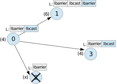
A simple test (create a new comm with MPI COMM SPLIT, initiate the non-blocking MPI IBARRIER at one process in the comm and try to free the comm at all ranks) using MPICH MPI revealed, that by calling MPI COMM FREE, outstanding operations are indeed NOT completed. Additionally the communicator object does not get freed. By executing the test in a loop, the application terminates after some time with an error stating that the maximum amount of communicators is reached (in our case 2048 communicators) and no more can be created.
Behavior in our fault layer
Step 1: A simple synchronization operation (check dead processes) is executed with next op Default. We do this because after this operation the process with the highest count of recent NBC 1 operations is known to root.
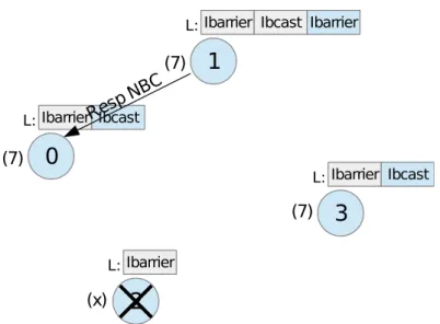
Step 2: Root sends a request message to the process with the highest count of recent NBC operations.
Step 3: The process responds the request with a serialized version of its local NBC vector.
Step 4: Another synchronization operation is startet, but this time with next op ’Commfree’. Root attaches the received serialized NBC vector to the synchroniza-tion broadcast and after this operasynchroniza-tion, all processes (including the dead ones) have the same NBC vector available. This ”remote” vector has an equal or greater size than the local recent non-blocking collectives vector. In MPI all NBC operations have to be executed in the same order at all ranks in the communicator, that’s why the first entries of the remote vector are identical to the entries of the local vector. (also see Figure 5.11)
Step 5: Let n be the size of the local recent NBC vector. Each process in the communicator begins executing the NBC operations stored in the remote NBC vector, beginning with the entry n+ 1.
Step 6: Each process completes all operations. For the first n operations, the request object from the local NBC vector is used (because they were initiated prior to the completion protocol). For the rest, the request object from the remote NBC vector is used (which were initiated in Step 5). The custom request objects are then deleted using C++ delete (because they were created dynamically using C++ new).
Step 7: The MPI communicator and all its copies created by our fault layer are deleted using MPI COMM FREE. The custom communicator is deleted from the local list of currently active communicators and the custom communicator object is deleted using C++ delete.
Figure 5.11: Local and remote vectors containing the information, which non-blocking operations were started, including the necessary parameters to complete them.
5.3 Implementation: functions and description
5.3.10.1 Detailed example
To get a better understanding of the functioning, we take a look at a detailed example. In our example we have four processes in the same MPI network and the same communicator (other than MPI COMM WORLD, because otherwise we couldn’t free the communicator). Each process executes the same MPI program (see Algorithm 2 for an excerpt of our very basic fictitious program).
Algorithm 2 1: MPI Ibarrier
2: MPI Wait . Wait for Ibarrier to complete
3: MPI Ibcast .With root process 1 and any message
4: MPI Wait . Wait for Ibcast to complete
5: MPI Ibarrier
6: MPI Wait . Wait for Ibarrier to complete
7: MPI Comm free . Free the comm where the operations were called
Right before calling MPI Ibcast (line 3), process 2 crashes. The following 10 Figures illustrate the behavior of the processes step-by-step. The number next to the processes indicates the currently executed line of the fictional algorithm. Process 0 is the root process of our custom communicator.
Behavior of our processes step-by-step
Figure 5.12: (1.) All processes call MPI Ibarrier. The call is stored in the local list of recent non-blocking collectives.
Figure 5.13: (2.) There are currently no failed processes, so after calling MPI Wait the Ibarrier is successfully completed at all ranks.
Figure 5.14: (3.) Process 2 fails and the layer immediately sends a dead message to root. The other processes have initialized an MPI Ibcast and wait for its completion.
5.3 Implementation: functions and description
Figure 5.15: (4.) Despite the present (but undetected) dead process, MPI Ibcast is quickly completed at process 1, because as root of the broadcast, the broadcast message is sent immediately by MPI and the buffer can be reused. After the completion of Ibcast, the Ibarrier is initialized and process 1 waits for its completion.
Meanwhile, after process 0 receives the dead message, it initializes a background dead broadbast to inform the other processes of the dead process.
Figure 5.16: (5.) All processes received the dead broadcast and return from their MPI Wait functions with an error. New non-blocking calls are also returned with an error.
All alive processes therefore reach MPI Comm free and initialize the completion protocol by reducing their current local NBC vector size.
Figure 5.17: (6.) Root of the communicator requests the NBC vector from the process with the greatest vector (process 1).
Figure 5.18: (7.) Process 1 responds the request with a message containing its local NBC vector elements.
5.3 Implementation: functions and description
Figure 5.19: (8.) Root sends the NBC vector to all processes in the communicator.
Figure 5.20: (9.) All processes receive the NBC vector and initialize non-blocking collectives newly received from the (remote) NBC vector and not yet in their local vector. All processes in the communicator have now access to the same list of non-blocking collectives.
Figure 5.21: (10.) All non-blocking collectives (local and remote) are completed at all ranks in the communicator. The communicator object and all its copies are then destroyed by MPI Comm free. The corresponding custom communicator object is deleted from the active communicators set.
5.4 Silent faults
5.4 Silent faults
We implemented a fault simulator to be able to simulate process failures in an MPI network. In section 2.1 we saw other possible fault models. While faults such as performance loss due to hardware malfunction is very hard to simulate, faulty memory leading to unwanted random bit flips can be easily simulated by manipulating bits directly in MPI messages.
Possible implementation
Let’s assume we have an array of n variables (like in Figure 5.22) being sent by MPI SEND. One variable in the array has the size of k bits, so a message with a total of kn bits will be sent. In our model, given a memory module is faulty, let the chance of an arbitrary bit being flipped (that means 1 will be changed to 0, 0 will be changed to 1) be 0< pf ≤1.
If we further assume, the event ’the bit at index j is being flipped due to a fault’ happens independent of any other possible flips, we can use the binomial distribu-tion along with a uniform distributed continuous random number generator and the Inverse transform sampling to calculate, how many of our kn bits are going to flip.
After we have calculated the number of bits to be flipped (let’s call the number
m) we fill a std::vector with the numbers 1,2, ..., kn. Then we shuffle our vector randomly (for example using std::random shuffle) and flip the bits in the message at the bit positions stored in the first m entries of the shuffled vector (or in other words: we choosem random bit positions from the set{1,2, ..., kn}).
Figure 5.22: A possible representation of a char array in the memory (the values are omitted). The tagged bit has the position 17.
Our implementation Sim FT Manipulate bits takes as parameters an integer array and its size, together with the probability of a bit flip. We make use of the standard C++ class binomial distribution to generate the amount of bits to be flipped, given a specific flip probabilityp.
Impact of bit flips on the application stability itself
Our model is only realistic, if with growing probability pf of bit errors, the
prob-ability of a total process failure pp also grows. That is because bit flips could not
only affect the messages, but also the system stability itself. If MPI or system critical areas of the memory are defective, the application or the operating system is very likely to crash or fail.
The probability of a process crash in a specific time range could for example consist of a constant partpc and a variable failure part depending on pf. Our model has
some requirements on our probability values:
(1.) Ifpf = 1, pp should be 1. If pc= 1, pp should be 1 as well.
(2.) If pf = 0, we want pp = pc. If pc = 0, we want pp = 1−(1−pf)k, where
k ≥ 1 is a value that should represent the size that the application uses in the memory (with greater program size, the impact of bit flips should be greater and more likely), greaterk results in a higher process failure probability.
(3.) We would likepp to be equal to or greater thanpcand equal to or greater than
pf. Also pp should be monotonically increasing if we change the valuespf or pc.
By combining these three requirements, our process failure probability could be
pp =pcpf + (1−pcpf)
pc+pf + (1−pf)pc+ (1−pc)(2−2(1−pf)k−pf)
2
!
wherepcwould be the process failure probability without taking the memory fault
into account andpf would be the probability of a single bit to be flipped. In Figure
5.23 you can see a plot ofpp using the parameter k = 3.
Figure 5.23: A plot ofppcreated using the parameterk = 3. The x-axis denotes the
values ofpf, the y-axis denotes the values of pc. The color represents
5.5 Other approaches
5.5 Other approaches
We presented a working solution to be able to simulate process faults in current MPI implementations. Our solution is a compromise between performance and compatibility. Because of the many other ways to create a fault simulator, we present possible other approaches, including clarifications why a particular other approach was not used for our implementation - this could be for example due to performance issues or missing functionality in MPI.
5.5.1 One master coordinates all failures
This is a simple approach, where a dead process reports to a coordinating master process immediately after calling Sim FT kill me. If another process attempts to send a message to a dead process, it requests an alive-status from the master process and proceeds depending to the masters’ answer. If the master process responds with ’the process is alive’, the MPI operation is executed, otherwise an error is returned to the application. This leads to some problems concerning consistency and performance.
On the one hand a process requesting the alive-status of another process might get the wrong information ’the process is alive’ due to network delay. After sending a message, the receiving process might be already dead an never receives the message, creating a deadlock at the sending process. This leads to the conclusion that either a message would need to be able to be cancele
![Figure 2.1: Different types of faults / fault models according to [KKL05].](https://thumb-us.123doks.com/thumbv2/123dok_us/387054.2542919/12.892.307.645.99.399/figure-different-types-faults-fault-models-according-kkl.webp)
![Figure 3.3: A possible combination of the last example with failed calculation of grid Ω [2,3]](https://thumb-us.123doks.com/thumbv2/123dok_us/387054.2542919/17.892.105.754.331.594/figure-possible-combination-example-failed-calculation-grid-ω.webp)