A
CTIVEF
LOWC
ONTROLT
ECHNOLOGYLinda D. Kral (deceased)
Washington University St. Louis, Missouri
INTRODUCTION
The ability to manipulate a flow field to improve efficiency or performance is of immense technological importance. Active flow control is one of the leading areas of research of many scientists and engineers in fluid mechanics. The potential benefits of flow control include improved performance and maneuverability, affordability, increased range and payload, and environmental compliance.
The intent of flow control may be to delay/advance transition, to suppress/enhance turbulence, or to prevent/promote separation. The resulting benefits include drag reduction, lift enhancement, mixing augmentation, heat transfer enhancement, and flow-induced noise suppression. The objectives of flow control may be interrelated, leading to potential conflicts as the achievement of one particular goal may adversely affect another goal. For example, consider an aircraft wing for which the performance is measured by the improvement in lift-to-drag ratio. Promoting transition will lead to a turbulent boundary layer that is more resistant to separation and increased lift can be obtained at higher angle of incidence. The viscous or skin-friction drag for a laminar boundary layer can be an order of magnitude smaller than for a turbulent boundary layer. However, a laminar boundary layer is more prone to separation resulting in a loss in lift and an increase in form drag. The design trade-offs of a particular method of control must carefully be evaluated and compromises are often necessary to reach a particular design goal.
CLASSIFICATION
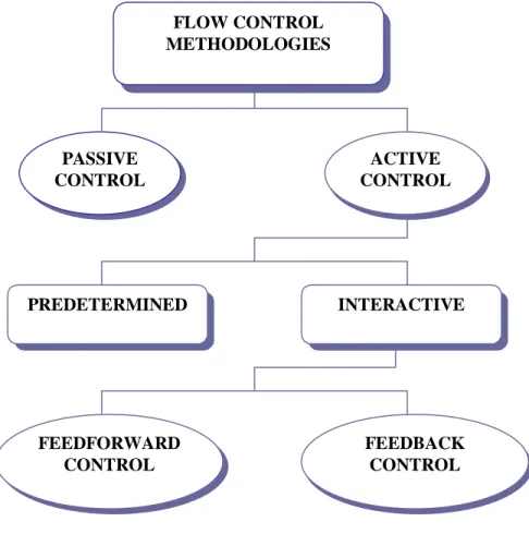
Classification of flow control methods is based on energy expenditure and the control loop involved as illustrated in Figure 1. Flow control involves passive or active devices that have a beneficial change on the flow field. A considerable amount of research has been performed using passive methods of flow control, which modify a flow without external energy expenditure. Passive techniques include geometric shaping to manipulate the pressure gradient, the use of fixed mechanical vortex generators for separation control, and placement of longitudinal grooves or riblets on a surface to reduce drag. Recent reviews of passive flow control include Bushnell and Hefner (1990) and Gad-el-Hak, et al. (1998). A detailed historical perspective on flow control is also given by Gad-el-Hak et al. (1998).
During the last decade, emphasis has been on the development of active control methods in which energy, or auxiliary power, is introduced into the flow. Active control schemes can be divided into predetermined or interactive methods. A predetermined method of control involves the introduction of steady or unsteady energy inputs without consideration for the state of the flow field. Examples of predetermined active flow control include jet vectoring using piezoelectric actuators (Smith and Glezer, 1997) and post-stall lift enhancement and form drag
reduction using oscillatory blowing (Seifert and Pack, 1999a). Predetermined open-loop control schemes can be very effective in modifying the flow field.
FLOW CONTROL METHODOLOGIES PASSIVE CONTROL ACTIVE CONTROL PREDETERMINED INTERACTIVE FEEDFORWARD CONTROL FEEDBACK CONTROL
Figure 1: Classification of flow control methods.
In interactive methods of flow control, the power input to the actuator (controller) is continuously adjusted based on some form of measurement element (sensor). The control loop for interactive control can be either a feedforward (open) or feedback (closed) loop. In the feedforward control loop, the sensor is placed upstream of the actuator. Therefore the measured flow field parameter and the controlled flow field parameter will differ as flow structures convect over stationary sensors and actuators.
The small-scale manipulation of the turbulent fluctuations is a challenging technological problem. In cases in which the control must interact with a specific set of turbulent fluctuations already present in the flow, such as random coherent structures, the effectiveness of an open-loop system is reduced. In the feedback control loop, a sensor is also placed downstream of the actuator to measure the controlled flow field parameter. The controlled variable is compared with the upstream reference variable. A feedback control law is utilized to control the energy introduced at the actuator. Moin and Bewley (1994) have classified interactive feedback control into four schemes based on the extent to which they are based on the governing flow equations: adaptive control, physical model-based, dynamical systems-based, and optimal control. A depiction of a closed-loop system is shown in Figure 2 for a boundary layer.
C losed-Loop C ontro l
Figure 2: Feedback control loop for active flow control. (Courtesy of D. E. Parekh, Georgia Tech Research Institute)
Feedback flow control involves the triad of flow phenomena, actuators/sensors, and
controls as depicted in Figure 3.Typical flow phenomena targeted for application of active flow
control are listed along with actuators, sensors and methods of control.Bewley (1999) discusses
the future of feedback flow control and the need for a renaissance approach where research must be conducted at the intersection of the traditional fields of fluid mechanics, mathematics, and control theory for successful application of feedback control schemes. A consideration of both the fundamental flow physics and the requirements and limitations of control algorithms must be understood. ACTUATORS • Fluidic • Thermal • Acoustic • Piezoelectric • Synthetic Jets • Electromagnetic
• Shape Memory Alloys
• MEMS
CONTROLS & SENSORS
ACTUATORS Boundary Layers
• Separation Control
• Drag Reduction
• Noise Suppression • Virtual Surface Shaping
FLOW PHENOMENA
Vortex Flows
• Forebody Vortex Control
• Blade-Vortex Interaction
• Wing-Tip Vortex Dynamics
• Vortex Generation/Alleviation
CONTROLS
• Neural Networks
• Adaptive
• Physical Model-Based
• Dynamical Systems Based
• Optimal Control Theory
Jets, Wakes, Mixing Layers • Mixing Enhancement • Jet Vectoring • Noise Suppression • Wake Modification SENSORS • Conventional • Optical • MEMS A ACCTTIIVVEE F FLLOOWW C CONONTTROROLL T TRIRIAADD FLOW PHENOMENON
Figure 3: The feedback flow control triad. (Courtesy D. E. Parekh, Georgia Tech Research Institute)
There are two primary advantages to active flow control that are not achievable by passive techniques. First, active flow control technology leverages and controls a natural stability of the flow to attain a large effect using small, localized energy input. Control is most effective when the control input is introduced locally at a high receptivity region. For example, the effects of a control scheme can be dramatic when applied near the transition point of a boundary layer flow, the separation point on an airfoil, or the nozzle of a jet. Secondly, active control can be used to control complex, dynamical processes like turbulence production in turbulent boundary layers to reduce skin friction, and hence viscous drag, where the reduction is proportional to the surface area covered by the actuators. The mechanism of turbulence production in boundary layers is understood as a complex series of dynamical events associated with organized, near-wall, low-speed streaks and their instabilities. This process culminates in a sudden eruption, or bursts, of low-momentum fluid away from the wall. As discussed by Bushnell (1985), the correct phasing of the control inputs with respect to the organized flow structures may be the key factor in the success of a control scheme. Lumley and Blossey (1998) present several applications of active control of turbulent flow using the latter approach of modifying the production of turbulence.
Sensors
Flow sensors need to be robust and not significantly alter the flow field that is measured. For practical reasons, most flow sensors for active flow control are flush mounted on a solid surface. At the solid surface, typically wall pressure and/or skin friction can be measured. For situations in which the wall pressure is important, there are many devices for measuring pressure fluctuations, which are essentially small microphones. Some examples of sensors for measuring wall shear stress include floating element sensors, hot films, and shear stress crystals.
Actuators
There are many types of actuators that can be used in active flow control, as listed in Figure 3. One of the greatest challenges in making active flow control technology practical is the development of robust actuators. Desired characteristics of actuators include low power consumption, fast response, reliability, and low cost. Three different actuator concepts are highlighted below to give a brief overview of the variety of actuators that can be used in flow control.
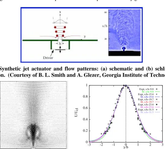
A recent breakthrough in actuator concepts is the synthetic jet actuator developed at Georgia Institute of Technology. A schematic of this actuator is shown in Figure 4. This class of actuators uses an oscillatory surface within a cavity to generate a jet from the flow that is being controlled without the need for mass injection (Smith and Glezer, 1998). The jet shown in Figure 4 was generated with a piezoelectric diaphragm in a periodic manner. Flow enters and exits the cavity through an orifice. On the intake stroke, fluid is drawn into the cavity from the area surrounding the orifice. As this fluid is driven out of the cavity, a shear layer is formed between the expelled fluid and the surrounding fluid. This layer of vorticity rolls up to form a vortex ring. By the time the diaphragm begins to move away from the orifice to pull fluid back into the cavity, the vortex ring has moved far enough away that it is virtually unaffected. Thus a train of vortex rings is created by the actuator. In the mean, the velocity profile appears similar to a steady jet. Actuators of this type have been shown to exert significant control authority in
many applications and have the additional benefits of being compact and requiring no flow plumbing. A variety of flow control results have been achieved using the synthetic jet actuator including thrust-vectoring, mixing enhancement, separation control and virtual surface shaping (Smith and Glezer, 1997; Smith et al., 1997; Amitay et al. 1997; Amitay et al., 1999; Amitay and Glezer, 1999; Smith et al., 1998, and Smith et al., 1999). These wealth of applications illustrate the great potential for this type of actuator to be applied to air vehicles for aerodynamic control.
Kral et al. (1997a) have simulated the synthetic jet actuator developed at Georgia Institute of Technology and obtained excellent agreement with the experiments of Smith and Glezer (1998). Figure 5 shows instantaneous velocity vectors from the simulations halfway through the cycle. Pairs of counter-rotating vortices are observed in both the simulations and experiments, but quickly diffuse. Also shown in Figure 5 are comparisons between the simulations and experiments of time-averaged velocity profiles for the mean streamwise velocity. Agreement between the experiments and computations is very good.
Figure 4: Synthetic jet actuator and flow patterns: (a) schematic and (b) schlieren flow visualization. (Courtesy of B. L. Smith and A. Glezer, Georgia Institute of Technology)
0 0.2 0.4 0.6 0.8 1 -3 -2 -1 0 1 2 3 U/U cl y/b Expt, x/h=9.8 SJ, x/h=9.8 Expt, x/h=15.6 SJ, x/h=15.6 Expt, x/h=19.7 SJ, x/h=19.7 Expt, x/h=23.6 SJ, x/h=23.6 Expt, x/h=31.5 SJ, x/h=31.5
Figure 5: Instantaneous velocity vectors for a turbulent synthetic jet actuator (left side) and comparison between simulation and experiment for the mean streamwise velocity. (Experimental results courtesy of B. L. Smith and A. Glezer, Georgia Institute of Technology)
Smith and Glezer (1997) and Smith et al. (1999) have also investigated controlled interactions of adjacent synthetic jets. The strong entrainment of ambient fluid that is induced
near the flow orifice by the jet formation is exploited for dynamic vectoring of adjacent jets by varying the relative phase of their driving waveforms. Figure 6 shows the effect of varying phase angle between the driving signals of adjacent jets. If the two jets are in phase (left figure), the inner vortices of each vortex pair cancel each other, resulting in a single, wider, synthetic jet.
When the jet on the left is leading in phase by 60°, the merged jet is vectored to the left (middle
photo). For a phase angle of 130° (right photo), the merged jet becomes attached to the exit
plane. Kral and Guo (1999) have simulated the vectoring of adjacent synthetic jets and obtained very good agreement with the experiments of Smith et al. (1999).
Figure 6: Schlieren images of adjacent synthetic jets which demonstrate the effect of varying the phase angle between the two driving signals (left photo shows two jets in phase, middle photo depicts the left jet leading in phase by 60°, and the right photo shows the left jet leading in phase by 130°. (Courtesy of B. L. Smith and A. Glezer, Georgia Institute of Technology)
A promising actuator concept recently developed by Cattafesta et al. (1999) for cavity noise suppression is shown in Figure 7. This actuator is an improved design over the first-generation piezoelectric flaps developed by Cattafesta et al. (1997). The first first-generation piezo flaps exhibited a tendency to fail mechanically before reaching their respective electrical limitations. The second-generation actuator is used to construct an active, segmented flap at the upstream separation edge of the cavity and is called a monolithic, piezoelectric flap actuator. The separation edge is an appropriate choice for active control devices because it is the location of maximum receptivity.
FLOW Metal Contact Aluminum Cantilever Piezoceramic Gap Flow
Figure 7: Monolithic piezoelectric flap actuator for suppresion of cavity noise. (Courtesy of L. N. Cattafesta, III, High Technology Corporation)
The third actuator concept highlighted here is a Lorentz-force actuator. Experiments performed by Nosenchuck and Brown (1992), Nosenchuck et al. (1995), and Nosenchuck (1996) using a specific electromagnetic forcing have indicated that viscous drag can be reduced by as much as 90%. Flush-mounted Lorentz force actuators are used to induce a current-density field,
j, and a magnetic field, B, in the vicinity of the wall to provide a three-dimensional body force L=j x B. A schematic of a Lorentz force actuator is shown in Figure 8. The actuator is
comprised of a pair of subsurface permanent magnets and two surface-mounted. The magnets and electrodes are arranged such that the electric and magnetic fields intersect and create a three-dimensional Lorentz force above the actuator. The curl of the Lorentz force represents a source of vorticity. Donovan et al. (1997) and Cary et al. (1999) have performed a detailed analysis of the vorticity generated over a single EMTC actuator.
Figure 8: Schematic of a Lorentz force actuator (The smaller rectangles represent surface mounted electrodes).
MEMS
One of the major advances in flow control is the emergence of Micro Electro Mechanical Systems (MEMS) technology, which employs the methods developed for the fabrication of silicon chips to construct very small-scale mechanical devices. The significance of micromachine technology is that it makes it possible to provide mechanical parts of micron size, batch fabricated in large quantities, and integrateable with electronics. Miniaturization to this scale is necessary for both sensors and actuators for successful feedback control of turbulence due to the very small scales of the coherent structures in high-Reynolds-number flows of engineering interest. Miniaturized actuators also simplify the integration of the control system with the overall structure or subsystem. MEMS fabrication processes provide not only miniaturization, but also modular integration of sensors, actuators, and electronics and the affordability enabled by batch processing. However, micro devices for active flow control do not obviate the role of meso devices in flow control technologies. Recent review articles on the use of MEMS for active flow control include McMichael (1996) and Ho and Tai (1996, 1998).
APPLICATIONS
To successfully apply active flow control, several basic questions should be answered. First the control objective to be achieved is specified (e.g., increased lift). Secondly, the flow phenomenon to be controlled or leveraged is identified (e.g., boundary layer separation). Flow physics is key to scaling and determining influential parameters. An appropriate actuation strategy is then selected (e.g., predetermined open-loop control or feedback control). Finally, a range of operation for the key control parameters is determined (e.g., forcing frequency and amplitude). Several recent successful applications of active flow control are highlighted. The review is intended to provide a sampling of some of the on-going research in this burgeoning area of fluid mechanics.
Separation Control over Airfoils
Active manipulation of separated flows over airfoils at moderate and high angles of attack has been the focus of a number of investigations for many years. The objective of these investigations is to improve the aerodynamic performance and extend the flight envelope by inducing complete or partial flow reattachment. Reattachment is normally affected by exploiting the receptivity to external excitation of the separating shear layer, which affects the evolution of the ensuing vortical structures and their interactions with the boundary layer. The ability to change lift without changing angle of attack or flap deflection is beneficial in many areas. The prevention of separation and the generation of high lift is an important aspect of flow control.
Active flow control investigations for separation control on an airfoil have employed a variety of techniques including external and internal acoustic excitation, vibrating mechanical flaps, and steady and unsteady blowing. Research in this area is blooming and the potential performance benefits are very encouraging. An overview of some of the encouraging work in this area is discussed. Seifert et al. (1993, 1996) have experimentally demonstrated delay of airfoil stall by oscillatory blowing. It was found that oscillatory blowing can delay separation much more efficiently than steady blowing that is traditionally used for this purpose. Both zero-mass and pulsed jets were investigated in addition to steady blowing. Relatively low momentum
oscillations were superimposed on a small amount of steady blowing, introduced tangentially to the surface. The oscillatory blowing required one to two orders of magnitude smaller amount of oscillatory momentum to achieve comparable gains as steady blowing. The improvements in lift are attributed not only to attaching the flow to the surface, but also to effectively eliminating a large wake region existing above the attached flow when the steady blowing is weak. Seifert et
al. (1996) examined the dependence on many parameters, including location of the blowing slot,
the steady and oscillatory momentum coefficients of the jet, and the frequency of the imposed oscillations.
Several numerical investigations of post-stall flow control have been undertaken that have shown the beneficial effects of oscillatory blowing in lift enhancement (e.g., Wu et al., 1998 and Donovan et al., 1998). Donovan et al. (1998) simulated the NACA 0015 experiment
of Seifert et al. (1996) at Rec=1.2 x 10⁶ and showed good agreement with the lift increment due
to the oscillatory forcing. They showed that the lift enhancement is due to large-scale vortical structures convecting over the suction surface that provide a lower average pressure than in the unforced case. In the mean, the flow is “more attached” than in the case without forcing, but instantaneously, significant separated regions still exist. Figure 9 shows instantaneous pressure
distributions from the simulations of Donovan et al. (1998) at α =22°. The presence of two
coherent structures on the suction surface at every phase of the forcing is seen. The amplitude of the pressure oscillations on the suction surface decreases with increasing streamwise distance, while the amplitude along the lower surface of the airfoil is negligible. The instantaneous pressure distributions are in good qualitative agreement with the experiments. Details of the flow field dynamics can be found in Donovan et al. (1998), as well as simulations of lift enhancement using steady and synthetic jet actuators for a NACA 0012 airfoil.
Figure 9: Phase-locked pressure distributions for a NACA 0015 airfoil at α =22°and Rec=1.2 x 10⁶.
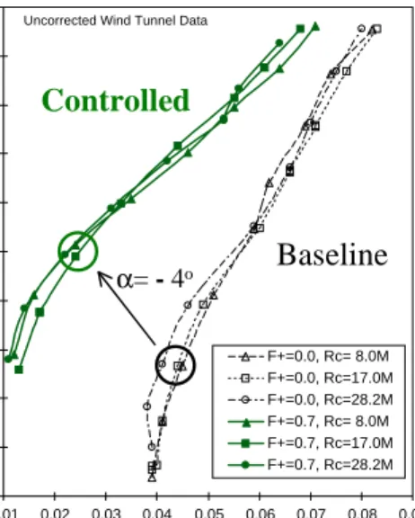
Recently, this active flow control technology was demonstrated at higher Reynolds numbers, corresponding to a jet airplane at take-off conditions, by Seifert and Pack (1999a) with similar trends in lift augmentation. Figure 10 presents the lift-form-drag polars of the baseline
-6 -5 -4 -3 -2 -1 0 1 0 0.2 0.4 0.6 0.8 1 Cp x/c Average (controlled) Average (uncontrolled) = 90 deg φ = 180 deg φ = 270 deg φ = 360 deg φ
and controlled-flap airfoil at Reynolds number based on chord of Rec = 8.0 x 10⁶, 17.0 x 10⁶, and
28.2 x 10⁶. Form drag is the main cause of the increase in drag for separated flows. Most of the
drag for this case is caused by the stalled flap, which is separated at all angles of attack. The excellent agreement for the three sets of data shows that there is no Reynolds number sensitivity to the separation control method. The circles superimposed on the figure denote data acquired at
° − = 4
α showing the increase in lift coefficient and the reduction in form drag.
-0.2 0 0.2 0.4 0.6 0.8 1 1.2 1.4 1.6 1.8 0.01 0.02 0.03 0.04 0.05 0.06 0.07 0.08 0.09 Cdpu Clu F+=0.0, Rc= 8.0M F+=0.0, Rc=17.0M F+=0.0, Rc=28.2M F+=0.7, Rc= 8.0M F+=0.7, Rc=17.0M F+=0.7, Rc=28.2M
Uncorrected Wind Tunnel Data
Baseline
Controlled
α= - 4o
Figure 10: Lift-form drag polars for the NACA 0015 airfoil at M=0.2 with flap deflected20° and control applied on the upper surface at X/c=0.7. (Courtesy of A. Seifert and L. G. Pack, NASA Langley Research Center)
Compressibility effects on post-stall lift enhancement at flight Reynolds numbers have also been investigated by Seifert and Pack (1999b). Figure 11 shows the increase in lift and decrease in form drag obtained with oscillatory blowing at Mach 0.28 and Mach 0.4. The
gradual nature of the response to the oscillatory momentum blowing coefficient, <cµ >, is also
depicted. Another recent result by Seifert and Pack (1999b) is the control of shock-induced separation at Mach 0.55. While high lift is seldom required at transonic speeds, since the sizing of the wing is made to meet take-off requirements, active separation control at compressible speeds can be utilized to delay the onset and alleviate the effects of buffet. Also, rotary wing aircraft can benefit from rapidly changing lift and drag using active flow control with jets at transonic speeds (Hassan et al., 1997). Oscillatory blowing modifies the shock intensity and location when introduced slightly upstream of the shock. For this configuration at Mach 0.55, the relative lift to drag ratio increased by 35% nearly linearly with increased oscillatory blowing. This trend is highly desirable for a linear controller.
M=0.28 & 0.4, Rc=12.7x10⁶ -0.1 0.1 0.3 0.5 0.7 0.9 1.1 1.3 1.5 0 2 4 6 8 10 12 14 α [o ] Cl ∆Cl Cl, F+=0, M=0.28 Cl, F+=2, M=0.28 Cl, F+=0, M=0.4 Cl, F+=2.1, M=0.4 dCl, M=0.4 dCl, M=0.28 0.5 0.7 0.9 1.1 1.3 1.5 0.0001 0.001 0.01 0.1 <cµ> [%] Cl 0.08 0.12 0.16 0.2 0.24 0.28 Cdp Lift Form Drag M=0.28, α=14o
Figure 11: The effects of Mach number and periodic excitation on the lift and form drag of a NACA 0015 airfoil. (Courtesy of A. Seifert and L. G. Pack, NASA Langley Research Center)
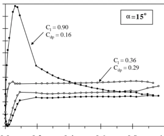
Separation control over cylindrical bodies and airfoils has also been obtained using synthetic jet actuators. Smith et al. (1998) used a synthetic jet, positioned near the leading edge of a thick airfoil, to reattach the separated shear layer present on the upper surface of the airfoil at stall. Due to the nature of a synthetic jet, this excitation was necessarily unsteady with no net mass addition to the flow. Figure 12 shows the pressure distribution over the airfoil with and without control applied. The lift coefficient more than doubled, while the drag coefficient was reduced by a factor of two. This experimental work explored the effect of jet location and amplitude on the separation control efficiency. It was demonstrated that as the position of the jet approached the separation point in the stalled flow, the jet amplitude required to reattach the separated flow decreased by more than an order of magnitude. Additional experiments of separation control using synthetic jet actuators by Amitay et al. (1997), Amitay et al. (1999), and Amitay and Glezer (1999) have also shown large improvements in lift.
-4.0 -3.5 -3.0 -2.5 -2.0 -1.5 -1.0 -0.5 0.0 0.5 1.0 0.0 0.2 0.4 0.6 0.8 1.0 x / c Cp αα=15o Cl = 0.36 Cdp = 0.29 Cl = 0.90 Cdp = 0.16
Figure 12: Pressure distribution over a thick airfoil at 15° angle of attack. (Courtesy of D. R. Smith, University of Wyoming)
Thrust Vectoring
A thrust vectoring system has typically required a variation of nozzle geometry. The greater mechanical complexity in the system can account for as much as 30% of the weight of the jet engines and significantly increase the cost. Fluidic jet control provides an alternative approach to control the aerodynamic flow of the jet for fixed nozzle geometry. Fluidic devices are potentially attractive for shear flow control for several reasons: they have no moving parts, they can produce excitation that is controllable in frequency, amplitude and phase, they can operate in harsh thermal environments, they are not susceptible to electromagnetic interference, and they are easy to integrate into a functioning device. There have been many investigations into fluidic jet control and a few of these studies are highlighted below.
An effective method to vector a conventional jet has been discovered by Smith and Glezer (1997). A synthetic jet actuator is placed adjacent to the exit plane of a high aspect ratio rectangular primary jet as shown in Figure 13. The location of the synthetic jet actuator is depicted. Schlieren visualizations of the flow with and without control are shown. The vectoring results from the synthetic jet drawing fluid from the primary jet conduit. The flow near the top of the duct accelerates, while the pressure along the top is reduced, resulting in a vertical pressure gradient in the duct. Kral and Guo (1999) have also captured the vectoring in numerical simulations using the same conditions as the experiments of Smith and Glezer (1997).
Figure 13: The top schlieren image shows the primary jet unforced. The bottom schlieren image shows the synthetic jet is activated and the primary jet vectored toward the actuator at an angle of nearly 30°. (Courtesy of B. L. Smith and A. Glezer, Georgia Institute of Technology)
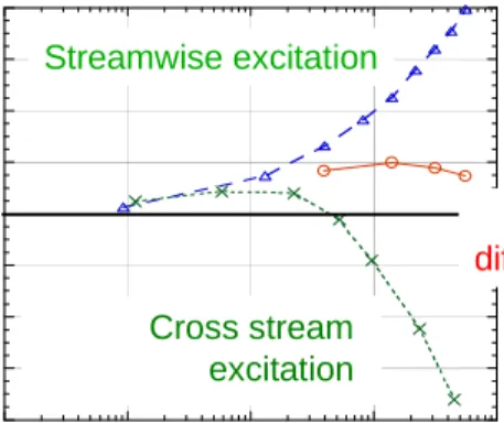
Pack and Seifert (1999) performed another recent successful jet vectoring experiment. A short, wide-angle diffuser was attached to the exit of a jet and excitation was introduced at the junction between the jet exit and the diffuser inlet. Introduction of high amplitude, periodic excitation at the jet exit enhances the mixing and promotes attachment of the jet shear layer to the diffuser wall. Vectoring is achieved by applying the excitation over a fraction of the circumference of the circular jet, enhancing its spreading rate on the excited side and its tendency
to reattach to that side. Figure 14 shows the jet deflection angle versus the oscillatory blowing coefficient for streamwise and crosstream excitations. Depending on the direction of excitation, the jet is deflected upwards or downwards. Also shown in Figure 14 is the effect of the diffuser attached at the jet exit in enhancing the effectiveness of the streamwise excitation.
-8 -6 -4 -2 0 2 4 6 8 0.001 0.01 0.1 1 10 Streamwise no diffuser Streamwise diffuser Cross-stream diffuser
deflection angle [deg]
<cµ> % Streamwise excitation No diffuser Cross stream excitation
Figure 14: The effect of excitation direction and presence of a diffuser on jet deflection angle plotted as a function of the excitation oscillatory momentum coefficient. (Courtesy of L. G. Pack and A. Seifert, NASA Langley Research Center)
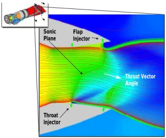
Another promising approach for thrust vectoring is fluidic throat skewing. In a recent computational investigation, Miller et al. (1999) showed promising results with this method of active flow control. The fluidic throat-skewing concept combines design features added for optimum jet throat area control with additional features for efficient thrust vectoring. The fluidic throat skewing concept for nozzle flow control features symmetric injection around the throat region to provide aerodynamic throttling for jet area control and asymmetric injection to subsonically skew the sonic plane for thrust vector control. An injection slot is located at the throat and nozzle flap on both sides of the nozzle. These details are shown in Figure 15. By injecting asymmetrically at the throat, the sonic plane is actually reoriented, which subsonically turns the nozzle primary flow (as opposed to flow turning accomplished by the formation of a shock). Supplemental injection ports downstream of the throat injection ports are also used to further skew the sonic plane and increase the vector angle. By controlling the injection flow rate at the throat and flap, vectoring can be provided at all throttled operating conditions.
Miller et al. (1999) investigated the nozzle performance with injection at various throttling and vector angle conditions. Figure 16 illustrates how vectoring is accomplished from maximum throttling (minimum throat area) to minimum throttling (maximum throat area) by varying the injection mass flow distribution in the nozzle. Varying injector flow split is the key control parameter to effectively decouple thrust vectoring from throat area control (throttling) in the fully fixed nozzle. At minimum effective throat area, an unvectored condition is achieved by injecting a symmetric distribution of mass flow at the throat (Figure 16, Label A). Vectoring is obtained at minimum effective area by injecting on one side of the throat, setting up an asymmetric flow field (Figure 16, Label B). To vector the nozzle stream at moderate effective throat areas, an injection mass flow is redistributed from the throat to the divergent flap on the opposing wall (Figure 16, Labels C and D). Injection at the divergent flap further skews the sonic plane from the throat, achieving an even greater vector angle. As more mass flow is redistributed
from the throat to the flap injector, the primary flow is throttled less, and the effective throat area increases. When all the injected mass flow is moved to the flap, the largest effective throat area is produced (Figure 16, Label E). To achieve a non-vectored condition at maximum effective throat area), the injected mass flow is turned off (Figure 16, Label F). All points within this envelope can be achieved through similar redistribution of injected flow.
Throat Injector Flap Injector Sonic Plane Thrust Vector Angle
Figure 15: Pressure contours of fluidic throat skewing from numerical simulation at M=0.9, 36,000 ft, and Nozzle Pressure Ratio=5.5 (red contours represent regions of high pressure and blue contours represent regions of low pressure). (Courtesy of D. N. Miller, Lockheed Martin Tactical Aircraft Systems)
Effective Throat Area
Vector Angle
0 Ma xim u m Thro ttling (Se t by E ng ine Stab ili ty Lim it) Mi nimu m Thr ott ling (Se t by G eo m etri c Th roat)Minimum Area Maximum Area
A
B D E
F C
Figure 16: Fluidic throat skewing performance envelope (vectoring at all throttled conditions). (Courtesy of D. N. Miller, Lockheed Martin Tactical Aircraft Systems)
The system of vortices that forms and separates from the forebody of aircraft and missiles at high angles of attack is a significant contributor to the aerodynamic loads acting on the vehicle. A variety of different vortex configurations may result that is dependent on the angle of attack. The forebody vortices may be symmetric or asymmetric with respect to the plane of the body. Strong yaw moments are generated in the asymmetric case and this is referred to as “phantom yaw”. The flow asymmetry is characterized by vortices that curve away from the body from alternate sides and ultimately align themselves with the freestream direction. Experimental evidence shows that the asymmetric vortices are sensitive to minute imperfections in the model and to freestream disturbances.
It is highly desirable to control both the strength and configuration of the separating vortices in order to manage the forces acting on the flight vehicle. If the asymmetric vortex system can be made symmetric, the side forces are eliminated. The control technique can also be used to determine the sign of the force, thus utilizing the vortices to turn the vehicle. Recent research by Roos and Magness (1993) and Roos (1996a) has demonstrated that the vortex instability can be manipulated with slight, controlled perturbations introduced near the forebody nose, which is the region of maximum flow sensitivity. Using very small levels of blowing (microblowing) through flush ports in the forebody nose, as shown in Figure 17, forebody vortex
asymmetry was controlled at very high angles of attack (α >50°). Roos (1996b) has also
applied microblowing to a hemisphere-cylinder forebody shape, which is typical of missile geometries. The microblowing was effective in producing and controlling vortex and force asymmetry on the hemisphere-cylinder.
Figure 17: Vortex-asymmetry triggering effect of microblowing control jets on blunted tangent ogive forebody. (Courtesy of F. W. Roos, The Boeing Company)
Williams et al. (1989) have investigated an unsteady base bleed control method which also shows promise in reducing vortex asymmetry for a cone-cylinder geometry. The supply of fluid was purely unsteady with no net mass addition, but provided a net momentum addition to the flow due to a reduction in mean pressure at the exit of the control port. Even though the blowing requirements for microblowing are very slight, the newly developed technology of synthetic jet actuators has been employed in experiments by Roos (1998) of forebody vortex asymmetry control to demonstrate the ability to achieve microblowing results without the need for any pneumatic plumbing or control-jet gas supply, as shown in Figure 18.
Figure 18: Comparison of synthetic jet and steady jet flow control for a hemisphere-cylinder forebody. (Courtesy of F. W. Roos, The Boeing Company)
Control of Flow-Induced Cavity Resonance
Cavity flows are important for a wide range of applications including landing gear and weapons bays in aircraft to flow over ground vehicles. Suppression of flow-induced cavity oscillations is an important flow-control problem. A complex feedback process, as shown in Figure 19, characterizes cavity flows. Convective instabilities grow to saturation in a shear layer, impinging near the downstream corner of the cavity. This generates disturbances that travel upstream to the separation edge and some of the disturbance energy is converted to an instability wave at the upstream separation edge. This process generates large amplitude frequency tones in and around the cavity. The large sound pressure levels (SPL) induce significant vibrations, which can have a detrimental effect on the contents of the cavity.
Figure 19: Schematic of complex feedback process for flow past a cavity. (Courtesy L.N. Cattafesta III, High Technology Corporation)
An investigation of active control of flow-induced cavity resonance at low Mach numbers (M<0.2) was performed by Cattafesta et al. (1997). Active control was achieved using
piezoelectric unimorph actuators with an active, segmented flap constructed at the upstream separation edge (see Figure 20). Both open-loop and closed-loop control provided comparable results in eliminating the tone associated with flow-induced resonance. Using open-loop control for a deep cavity (L/D=0.5), the broadband SPL is reduced from 144 to 126 dB (a factor of 8 reduction in amplitude). The peak in the amplitude spectrum at 230 Hz is reduced by approximately 23 dB at the expense of raising the level at the excitation frequency by almost 15 dB.
Figure 20: Schematic of active control scheme for flow-induced cavity resonance. (Courtesy of L. N. Cattafesta III, High Technology Corporation)
Figure 21 shows the optimum results for a deep cavity using feedback control. A reduction of about 20 dB is achieved in the broadband SPL. In the feedback control loop, the actuators are activated at a high power level for a fraction of a second and then the power input to the actuators is significantly reduced after the system is under control. The closed-loop control required an order-of-magnitude less power than the open-loop control.
In both cases, the mean shear layer was unaffected by the control input, indicating no associated drag penalty due to the control technique. Although the effectiveness of control was similar for both the feedforward and feedback control techniques, the fundamental mechanisms for noise suppression are fundamentally different. In the open-loop case, the fundamental instability mode is overwhelmed by the introduction of a sufficiently strong disturbance at a different frequency that is not properly synchronized with the feedback loop. A threshold behavior with respect to the amplitude of control input required to create a significant reduction in cavity SPL was observed. In the closed-loop case, the feedback disturbance generated by the flow impingement at the downstream cavity edge was effectively cancelled by the active leading edge, inhibiting the generation of the fundamental instability mode.
Frequency (Hz) 0 200 400 600 800 1000 SP L ( d B) 40 60 80 100 120 140 160 Uncontrolled SPL 143.4 dB Feedback Control SPL 123.3 dB
Figure 21: Amplitude spectra of cavity (L/D=0.5) with and without closed-loop control. (Courtesy of L. N. Cattafesta III, High Technology Corporation)
In another investigation of cavity noise suppression, Raman et al. (1999) used miniaturized (1 mm inner diameter) bi-stable fluidic nozzles developed by Bowles Fluidics Corporation (Raghu & Raman, 1999) to suppress cavity tone resonance. Figure 22 shows the location of the fluidic device in the jet-cavity configuration. Figure 23 shows the effect of fluidic excitation on the resonant cavity tone. With upstream excitation, the cavity tone is suppressed by 10 dB with only 0.12% (of the main flow) mass injection. Downstream excitation had no effect on the cavity tone. In addition, steady mass injection at the same levels had no effect on the cavity tones.
Figure 22: Schematic of jet-cavity configuration and fluidic device location. (Courtesy of G. Raman, Dynacs Engineering Co., Inc., NASA Glenn Research Center)
Figure 23: Fluidic oscillators supply pressure and mass-flow requirements for jet-cavity tone suppression. Mach number of main jet flow is 0.69. (Courtesy of G. Raman, Dynacs Engineering Co., Inc., NASA Glenn Research Center)
Raman (1997) also used two bi-stable fluidic nozzles located on either side of a larger scale primary rectangular nozzle. In a typical bi-stable fluidic nozzle, flow from the inner nozzle, issuing between the two sides of a nozzle attachment, attaches itself to either side due to the Coanda effect. The two fluidic nozzles with control ports were interconnected through their feedback tubes and then operated either in-phase or out-of-phase with respect to each other. The equalization of pressures through the feedback tube causes the jet to detach from one wall and attach to the other. Thus, an oscillating jet flow is obtained with no moving parts. Excitation in the in-phase (sinuous) mode resulted in a 35% enhancement of the mass flux of the primary jet. These examples demonstrate the potential for using bi-stable fluidic nozzles as practical excitation devices for a cavity noise suppressor or an airplane jet exhaust mixer.
Electromagnetic Turbulence Control
The applications discussed so far fall into the class of active flow control technology that leverages and controls a natural stability of the flow. The second class of active flow control modifies and controls complex, dynamical processes like turbulence production. Electromagnetic turbulence control (EMTC) belongs to the second class of active flow control methods. EMTC is a method of active flow control in which body forces are introduced that influence a large fraction of the boundary layer fluid, allowing more global control than previous techniques
Experiments of EMTC performed by Nosenchuck and Brown (1992), Nosenchuck et al. (1995), and Nosenchuck (1996) indicate that using a specific electromagnetic force distribution may reduce viscous drag by as much as 90%. The possibility of large gains suggests a fundamental change in the structure of the boundary layer that has yet to be fully understood. Unlike some earlier attempts to offset drag using magneto-hydrodynamic (MHD) thrust, the overall Lorentz force in this case is directed normal to the surface. The response of laminar and turbulent boundary layers to electromagnetic forces in seawater was experimentally investigated. Simulations by Kral and Donovan (1996) and Kral et al. (1997b) have captured many of the
salient features of these experiments. Experiments and simulations of both laminar and turbulent flows with EMTC active control are highlighted.
Laminar flow experiments by Nosenchuck et al. (1995) were conducted in a uniformly conducting fluid using an array of Lorentz-force actuators. Experimental flow visualization obtained using laser-induced-fluorescence is compared with particle traces from the simulations by Kral et al. (1997b) in Figure 24. An array of 16 actuators in the streamwise direction and four actuators in the periodic spanwise direction, with the magnets oriented spanwise to the flow direction, was used in both the computations and experiments. Both the experiment and simulation shows a periodic structure with rotational character. Velocity profile comparison between simulation and experiment are in reasonable agreement. The experiments and simulations were both very sensitive to hitting the resonance frequency for reinforcement of these structures.
Figure 24: Control of laminar flow using EMTC actuators. Top figure shows experimental flow visualization, while bottom figure depicts particle traces from numerical computations. (Experimental results courtesy of D. M. Nosenchuck, Princeton University)
Flow visualization of RANS simulations by Kral et al. (1997b) compares favorably with low-speed turbulent flow experiments by Nosenchuck et al. (1995). Four actuators in the streamwise direction, a four-phase cycling pattern, and spanwise magnets are simulated to match the experimental parameters. Oblique structures are observed in both the experiments and the computations as shown in Figure 25.
Figure 25: Flow structures in a turbulent flow with EMTC actuators (right figure is from experiments and left figure is from numerical simulations). (Experimental results courtesy of D. M. Nosenchuck, Princeton University)
The simulations capture many essential features of the flow field that have been experimentally found. Rotational structures in a thickening boundary layer are observed. The magnet orientation has a significant effect on the flow, primarily due to the difference in Lorentz force strength and distribution in the streamwise versus the spanwise direction. Regions of increased and reduced skin friction are observed as seen in the experiments. Aft of the actuators, the skin friction is reduced for the streamwise magnet orientation only in the simulations. Good agreement with experiment is seen in the laminar cases with laser sheet flow visualization and proper trends are captured in the velocity profiles. In the turbulent cases, the simulations show significantly smaller effects in the skin friction and drag changes when compared to the experiments.
Additional experiments and simulations have recently been conducted to attempt to better understand the flow structure development over and EMTC actuator and to determine mechanisms for drag reduction. The experimental and numerical results are in excellent agreement, including the perturbed velocity field (Cary et al., 1999 and Du et al., 1999).
GOVERNMENT INITIATIVES
Nearly all of the successful active flow control results just discussed were developed under government funding. Several government initiatives are demonstrating that active flow control technology is considered a high pay-off technology. A sampling of some recent initiatives and success stories by the Defense Advanced Research Projects Agency (DARPA), the Air Force Office of Scientific Research (AFOSR), the Air Force Research Laboratory (AFRL), and NASA Langley Research Center are overviewed. An overview of activities in active flow control by the ASME and the American Institute of Aeronautics (AIAA) is also given. This short synopsis is not meant to be exhaustive, but to give the reader an overview of government activity and sponsorship of active flow control technologies.
DARPA
DARPA has recently initiated a program on “Enabling Technologies for Micro Adaptive Flow Control” under the direction of Dr. James McMichael. The program was initiated in 1998 and plans three to six years of funding. Micro Adaptive Flow Control (MAFC) is defined as the ability to control the behavior of large-scale flow fields by exploiting natural flow response to small-scale disturbances triggered by small-scale actuators. The long-term program goals are to develop and validate enabling MAFC technologies and integrate MAFC technologies into high pay-off aero and hydro prototypical systems-level demonstrations. It is the intent of the MAFC program to explore and define the limits of flow control applicability to real systems, and to quantitatively assess the likely benefits and costs associated with system-level implementation. Systems are to be designed from the outset to be affordable, reliable, and have optimal performance using MAFC.
AFOSR/AFRL
AFOSR-funded research has led to the successful demonstration of active flow control technology to reduce jet engine exhaust temperatures on a full-scale JT8D-15 jet engine as shown in Figure 26. The top figure shows the uncontrolled exhaust plume and the bottom figure
demonstrates the effect of the pulsed jet, active core exhaust (ACE) control system. ACE control technology shortens and widens the exhaust plume resulting in a 50% temperature reduction at the flap location (5 diameters downstream). Boeing C-17 aircraft engineers believe that this temperature reduction could significantly reduce powered airlift costs. Active flow control allows for: (1) less expensive and lighter high-temperature aluminum to be used instead of titanium plates on the underside of C-17 flaps; (2) exhaust cooling to be applied only on take-off and landing; and (3) expensive and heavy core thrust reversers, which deflect hot plumes away from the loadmasters on the ground, to be replaced with active flow control systems. These factors have the potential to reduce life-cycle cost by up to $1.5 million per aircraft.
Figure 26: Active Core Exhaust (ACE) control technology reduces jet engine temperatures at the C-17 flap location by up to 50%. (Courtesy of AFOSR Research Highlights – September/October 1998)
The C-17 achievement began under an AFOSR basic research program, administered by Dr. James McMichael, in active flow control collaborative efforts at Georgia Institute of Technology, The Boeing Company, and the University of Arizona. Research in jet mixing, shear layer receptivity, and active flow control provided insight into the dynamics of the jet shear layer. Inherent instability modes of the jet that could be excited by various flow control devices at the nozzle exit were identified. The actuators included piezoelectric wedge actuators, pulsed jets, and zero-mass flux synthetic jets. In addition to the AFOSR program, Dr. Steven Walker of the Wright Laboratory Flight Dynamics Directorate (now Air Force Research Laboratory (AFRL)) initiated the Fluidic Injection Nozzle Technology (FLINT) program to develop fluidic actuator concepts for jet mixing, nozzle area control, and nozzle thrust vectoring. Implementing the fluidic concept reduces the weight and cost of the system. Under the FLINT program, a Boeing/Allied Signal/Pratt & Whitney contractor team, demonstrated the pulsed-jet, active core exhaust (ACE) control system on a full-scale JT8D-15 jet engine.
NASA
NASA Langley Research Center is highly focused on active flow control research. Pack and Joslin (1998) recently presented an overview of active flow control activities at NASA Langley Research Center. Several focused efforts at NASA include cavity oscillation control for noise suppression, boundary-layer separation control on airfoils using periodic momentum blowing, development of on-demand vortex generators for separation control during aircraft takeoff and landing and drag reduction during aircraft cruise conditions, and the development and testing of synthetic jet actuators for lift enhancement and forebody vortex control.
Another exciting program at NASA Langley Research Center is the NASA Aircraft Morphing program (Wlezien et al., 1998). The program is integrating research in seven disciplines to integrate smart technologies into high payoff aircraft applications. Smart systems are defined as embedded actuation, sensing, and control logic in a tightly coupled feedback loop. Goals of the program include active structural damping, active noise reduction, active flow separation control, and advanced health monitoring to reduce operations and maintenance costs. Technical Organizations
Technical organizations also play a key role in the development and directions of technologies. ASME recognizes the importance of active flow control in the field of fluid mechanics. The Fluid Mechanics Technical Committee (FMTC) has sponsored Forums on Control of Transitional and Turbulent Compressible Flows and Symposia on Control of Wall-Bounded and Free-Shear Flows at the ASME Fluids Engineering Division Summer Meeting. During the 1999 ASME/JSME Joint Fluids Engineering Conference, the Symposium on Control of Wall-Bounded and Free-Shear Flows filled ten sessions.
AIAA is also stressing active flow control as an important topic in fluid dynamics research. The Fluid Dynamics Technical Committee (FDTC) is highlighting active flow control as a key topic at the Fluids 2000 Conference in Denver, CO. Dr. James McMichael from DARPA is chair of the Flow Control Symposium at this meeting.
In addition, the AIAA FDTC has established a Subcommittee on Active Flow Control and is currently chaired by Dr. Steven Walker from AFOSR. This subcommittee is a replacement for the earlier National Committee on Active Flow Control (NCAFC) and meets bi-annually at the AIAA Aerospace Sciences Meeting and the AIAA Fluid Dynamics Meeting. The mission of this subcommittee is to co-sponsor multi-disciplined technical meetings focused on active flow control, host semi-annual forums at AIAA or other conferences to highlight key topics, and to provide a link to informational material regarding the technology.
FUTURE CHALLENGES
Successful implementation of active flow control requires an interdisciplinary approach, involving the classical disciplines of fluid mechanics, structural mechanics, material science, acoustics, systems, multidisciplinary optimization, and stability and control. Traditionally, technology development has occurred with researchers working in their own isolated fields of specialization. This trend has developed not only in universities, but also in government laboratories and industry. The recent trend has been to develop integrated, interdisciplinary, or multidisciplinary design teams to cross-fertilize and integrate component technologies. Coordinating research programs in which individual disciplines are supported in a collaborative environment will cultivate the development of breakthroughs in active flow control technologies. As the traditional fields are individually maturing, the integration of these disciplines holds exciting, uncharted new areas of research and technology development. The successful application of active flow control requires our willingness to not limit ourselves to one field of specialization, but to perform research and development in an interdisciplinary environment.
REFERENCES
Amitay, M., Honohan, A., Trautman, M., and Glezer, A., 1997, “Modification of the
Aerodynamic Characteristics of Bluff Bodies,” AIAA Paper No. 97-2004, 35th AIAA Aerospace
Sciences Meeting, Reno, NV, January.
Amitay, M., Kibens, V., Parekh, D. E., and Glezer, A., 1999, “Flow Reattachment Dynamics
over a Thick Airfoil Controlled by Synthetic Jet Actuators”, AIAA Paper No. 99-1001, 37th
AIAA Aerospace Sciences Meeting, Reno, NV, January.
Amitay, M. and Glezer, A., 1999, “Aerodynamic Flow Control of a Thick Airfoil using Synthetic
Jet Actuators,” ASME Paper No. FEDSM99-6922, Proceedings of the 3rd ASME/JSME Joint
Fluids Engineering Conference, Symposium on Control of Wall-Bounded and Free-Shear Flows, eds. L. D. Kral and T. Shakouchi, San Francisco, CA, July.
Bewley, T. R., 1999, “New Frontiers for Control in Fluid Mechanics: A Renaissance Approach,”
ASME Paper No. FEDSM99-6926, Proceedings of the 3rd ASME/JSME Joint Fluids
Engineering Conference, Symposium on Control of Wall-Bounded and Free-Shear Flows, eds. L.
D. Kral and T. Shakouchi, San Francisco, CA, July.
Bushnell, D. M., 1985, “Turbulence Sensitivity and Control in wall Flows,” Theoretical
Approaches to Turbulence, Applied Mathematical Sciences, Vol. 58, pp. 1-19.
Bushnell, D. M. and Hefner, J. N., 1990, “Viscous Drag Reduction in Boundary Layers,”
Progress in Aeronautics and Astronautics, Vol. 123, AIAA, Washington, D.C.
Cary, A. W., Donovan, J. F., and Kral, L.D., 1999, “Flow Structure Development over an Electromagnetic Turbulence Control (EMTC) Actuator,” ASME Paper No. FEDSM99-6932,
Proceedings of the 3rd ASME/JSME Joint Fluids Engineering Conference, Symposium on Control of Wall-Bounded and Free-Shear Flows, eds. L. D. Kral and T. Shakouchi, San
Francisco, CA, July.
Cattafesta, L. N. III, Garg, S. and Choudhari, M., 1997, “Active Control of Flow-Induced Cavity
Resonance,” AIAA Paper 97-1804, 4th AIAA Shear Flow Control Conference, Snowmass, CO,
June.
Cattafesta, L. N. III, Shukla, D., Garg, S., and Ross. J. A., 1999, “Development of an Adaptive
Weapons-Bay Suppression System,” AIAA Paper No. 99-1901, 5th AIAA Aeroacoustics
Conference, Seattle, WA, May.
Donovan, J. F. , Kral, L. D., and Cary, A. W., 1997, “Numerical Simulation of a Lorentz Force
Actuator,” AIAA Paper No. 97-1918, 4th AIAA Shear Flow Control Conference, Snowmass, CO,
June.
Donovan, J. F., Kral, L. D., and Cary, A. W., 1998, “Active Flow Control Applied to an Airfoil,”
Du, Y., Beskok, A., and Karniadakis, G. E., 1999, “Simulations of a Lorentz Force Actuator,”
ASME Paper No. FEDSM99-6933, Proceedings of the 3rd ASME/JSME Joint Fluids
Engineering Conference, Symposium on Control of Wall-Bounded and Free-Shear Flows, eds. L.
D. Kral and T. Shakouchi, San Francisco, CA, July.
Gad-el-Hak, M., Pollard, A., and Bonnet, J. P., 1998, “Flow Control: Fundamentals and
Practices,” Springer Lecture Notes in Physics, New Series Monographs, M53, Springer-Verlag,
Berlin.
Hassan, A. A., Straub, F. K., and Charles, B. D., 1997, “Effects of Surface Blowing/Suction on the Aerodynamics of Helicopter Rotor Blade-Vortex Interactions (BVI) – A Numerical Simulation,” Journal of the American Helicopter Society, Vol. 42, pp. 182-194.
Ho, C.-M. and Tai, Y.-C., 1996, “Review: MEMS and Its Applications for Flow Control,” ASME
Journal of Fluid Engineering, Vol. 118, pp. 437-447.
Ho, C.-M. and Tai, Y.-C., 1998, “Micro-Electro-Mechanical Systems (MEMS) and Fluid Flows,” Annual Review of Fluid Mechanics, Vol. 310, pp. 579-612.
Kral, L. D. and Donovan, J. F., 1996, “Numerical Simulation of Turbulence Control using Electromagnetic Forces,” Proceedings of the Forum on Control of Transitional and Turbulent
Flows, ASME Fluids Engineering Conference, eds. D. E. Parekh and R. K. Agarwal, Vol.
FED-237, pp. 319-329.
Kral, L. D., Donovan, J. F., Cain, A. B., and Cary, A. W., 1997a, “Numerical Simulation of
Synthetic Jet Actuators,” AIAA Paper No. 97-1824, 4th AIAA Shear Flow Control Conference,”
Snowmass, CO, June.
Kral, L. D., Donovan, J. F., and Cary, A. W., 1997b, “Numerical Simulation and Analysis of
Flow Control using Electromagnetic Forcing,” AIAA Paper No. 97-1797, 4th AIAA Shear Flow
Control Conference,” Snowmass, CO, June.
Kral, L. D. and Guo, D., 1999, “Characterization of Jet Actuators for Active Flow Control,” AIAA Paper No. 99-3573, 30th AIAA Fluid Dynamics Conference, Norfolk, VA, June.
Lumley, J. and Blossey, P., 1998, “Control of Turbulence,” Annual Review of Fluid Mechanics, Vol. 310, pp. 311-327.
McMichael, J. M., 1996, “Progress and Prospects for Active Flow Control using Microfabricated
Electro-Mechanical Systems (MEMS), AIAA Paper No. 96-0306, 34th AIAA Aerospace
Sciences Meeting, Reno, NV, January.
Miller, D. M., Yagle, P. J., and Hamstra, J. W., 1999, “Fluidic Throat Skewing for Thrust
Vectoring in Fixed-Geometry Nozzles,” AIAA Paper No. 99-0365, 37th AIAA Aerospace
Moin, P. and Bewley, T., 1994, “Feedback Control of Turbulence,” Appl. Mech. Rev., Vol. 47, No. 6, Part 2, S3-S13.
Nosenchuck, D. M. and Brown, G. L., 1992, “The Direct Control of Wall Shear Stress in a Turbulent Boundary Layer,” MAE Report T1954, Princeton University, Princeton, New Jersey. Nosenchuck, D. M., Brown, G. L., Culver, H. C., Eng, T. I., and Huang, I. S., 1995, “Spatial and Temporal Characteristics of Boundary Layers Controlled with the Lorentz Force,” Extended Abstract, Twelfth Australasian Fluid Mechanics Conference, Sydney, Australia.
Nosenchuck, D. M., 1996, “Boundary Layer Control Using the Lorentz Force,” Proceedings of
the Forum on Control of Transitional and Turbulent Flows, ASME Fluids Engineering
Conference, eds., D. E. Parekh and R. K. Agarwal, Vol. FED-237.
Pack, L. G. and Joslin, R. D., 1998, “Overview of Active Flow Control at NASA Langley
Research Center,” SPIE’s 5th Annual International Symposium on Smart Structures and
Materials, San Diego, CA, March.
Pack, L. G. and Seifert, A., 1999, “Periodic Excitation for Jet Vectoring and Enhanced
Spreading,” AIAA Paper No. 99-0672, 37th AIAA Aerospace Sciences Meeting, Reno, NV,
January.
Raghu, S. and Raman, G., 1999, “Miniature Fluidic Devices for Flow Control,” ASME Paper
No. FEDSM99-7526, Proceedings of the 3rd ASME/JSME Joint Fluids Engineering Conference,
San Francisco, CA, July.
Raman, G., 1997, “Using Controlled Unsteady Fluid Mass Addition to Enhance Jet Mixing,”
AIAA Journal, Vol. 35, pp. 647-656.
Raman, G., Raghu, S., and Bencic, T. J., 1999, “Cavity Resonance Suppression using Miniature
Fluidic Oscillators,” AIAA Paper No. 99-1900, 5th AIAA/CEAS Aeroacoustics Conference,
Seattle, WA, May.
Roos, F. W. and Magness, C. L., 1993, “Bluntness and Blowing for Flowfield Asymmetry Control on Slender Forebodies,” AIAA Paper No. 93-3409, AIAA Applied Aerodynamics Conference, August.
Roos, F. W., 1996a, “Microblowing for High-Angle-of-Attack Vortex Flow Control on a Fighter
Aircraft,” AIAA Paper No. 96-0543, 34th AIAA Aerospace Sciences Meeting, Reno, NV,
January.
Roos, F. W., 1996b, “Microblowing for Vortex Asymmetry Management on a Hemisphere-Cylinder Forebody,” AIAA Paper No. 96-1951, June.
Roos, F. W., 1998, “Synthetic-Jet Microblowing for Forebody Flow-Asymmetry Management,”
AIAA Paper No. 98-0212, 36th AIAA Aerospace Sciences Meeting, Reno, NV, January.
Seifert, A., Bachar, T., Koss, D., Shepshelovich, M., and Wyganski, I., 1993, “Oscillatory Blowing: A Tool to Delay Boundary-Layer Separation,” AIAA Journal, Vol. 31, No. 11, pp. 2052-2060.
Seifert, A., Darabi, A., and Wyganski, I., 1996, “Delay of Airfoil Stall by Periodic Excitation,”
Journal of Aircraft, Vol. 33, No. 4, pp. 691-697.
Seifert, A. and Pack, L. G., 1999a, “Oscillatory Control of Separation at High Reynolds Numbers,” AIAA Journal, June, to appear (also AIAA Paper No. 98-0214).
Seifert, A. and Pack, L. G., 1999b, “Oscillatory Excitation of Unsteady Compressible Flows over
Airfoils at Flight Reynolds Numbers,” AIAA Paper No. 99-0925, 37th AIAA Aerospace Sciences
Meeting, Reno, NV, January.
Smith, B. L. and Glezer, A., 1997, “Vectoring and Small-Scale Motions Effected in Free Shear
Flows Using Synthetic Jet Actuators,” AIAA Paper No. 97-0213, 35th AIAA Aerospace Sciences
Meeting, Reno, NV, January.
Smith, B. L. and Glezer, A., 1998, “The Formation and Evolution of Synthetic Jets,” Physics of
Fluids, Vol. 10, No. 9, September 1998, pp. 2281-2297.
Smith, B. L., Trautman, M. A., and Glezer, A., 1999, “Controlled Interactions of Adjacent
Synthetic Jets,” AIAA Paper No. 99-0669, 37th AIAA Aerospace Sciences Meeting, Reno, NV,
January.
Smith, D. R., Kibens, V., Parekh, D. E., and Glezer, A., 1997, “Thrust-Vectoring with Hybrid Synthetic Jet Actuators,” ASME Paper No. FEDSM97-3679, Proceedings of the 1997 ASME
Fluids Engineering Division Summer Meeting, Forum on High Speed Jet Flows, Vancouver,
B.C., June.
Smith, D. R., Amitay, M., Kibens, V., Parekh, D. E., and Glezer, A., 1998, “Modification of
Lifting Body Aerodynamics using Synthetic Jet Actuators,” AIAA Paper No. 98-0209, 36th
AIAA Aerospace Sciences Meeting, Reno, NV, January.
Williams, D. R., El-Khabiry, S., and Papazian, H., 1989, “Control of Asymmetric Vortices
around a Cone-Cylinder Geometry with Unsteady Base Bleed,” AIAA Paper No. 89-1004, 2nd
AIAA Shear Flow Control Conference, Tempe, AZ, March.
Wlezien, R. W., Horner, G. C., McGowan, A. R., Padula, S. L., Scott, M. A., Silcox, R. J., and
Simpson, J. O., 1998, “The Aircraft Morphing Program,” AIAA Paper 98-1927, 39th Structures,
Wu, J.-Z., Lu, X.-Y., Denny, A. G., Fan, M., and Wu, J.-M., 1998, “Post-Stall Flow Control on an Airfoil by Local Unsteady Forcing,” Journal of Fluid Mechanics, Vol. 371, pp. 21-58.