P a g e | 1463
Cfd Modeling of the In Cylinder Flow In Direct-Injection Diesel Engines
1.T Omsai*, 2.Mr.B.Pavannaik**, 3.Dr.M.Janardhan*** 4.G.Ramesh Babu****
*M.Tech Student**Associate Professor***Professor &Principal**** Associate Professor
Department of Mechanical Engg. Abdul Kalam Institute Of Technological Sciences,
Kothagudem,Khammam (DT) -507120
ABSTARCT:
Internal combustion engines today is the
best available source of reliable power for
all industrial applications, local transport a
large scale. It is called a key issue in the
efficiency of these engines. All attempts to
improve these engines tend to achieve
maximum efficiency. Is improving the
performance of diesel engines by
appropriate design of the multi-slot, exhaust
manifold, combustion chamber, piston, etc.,
the study on the impact of the configurations
of the cylinder piston on the development of
infrastructure. Here it is used for direct
injection diesel cylinder and a study. For
entry into multiple spiral density used a
combination helicalspiral. An increase in the
intensity of the vortex results in better
mixing of fuel and air. Swirling speeds in
the load can be significantly increased by
proper design pressure piston. In this paper,
it is a study on the impact of different air
traffic piston configuration and turbulence
within the cylinder direct injection (di)
diesel out using the code computational fluid
dynamics (cfd) fluent 13 . The
three-dimensional models of pistons and cylinders
openings are created in catia v5 and using
10.0 preprocessorhypermesh mix.
INTRODUCTION:
Internal combustion engine and was a big
part of the community for over 150 years. It
has dramatically increased human prosperity
and vital for our society that works day.
However, the combustion process has a not
inconsiderable negative european electronic
system, such as local and global emission of
pollutants side. Vehicle emissions have
shown pose a health hazard in many large
cities, among other things, of los angeles
that because of its location is particularly
prone to contamination. Smog is a serious
threat to health, the agency for
environmental protection (1998), and in
order to reduce smog emissions legislation
has been introduced. Europe began the
so-called european legislation in 1992 with
euro i standards governing oxides nitrogen,
nitrogen oxides and particulate blocks per
kilowatt hour of work. Since the
in january 2014, all new trucks that meet
european standards sixth.
Several strategies can be used to achieve
these objectives emissions. Examples of
such is the time of injection, selective
catalytic reduction (scr), and exhaust gas
recirculation (egr) to reduce emissions of
nitrogen oxide, as well as filters and high
injection pressure to reduce the mass of the
particle. In general, these strategies lead to
increased fuel consumption and / or cost.
Therefore, q trade between local emissions
(nitrogen oxides and particulates) and global
emissions (second self-bonn dioxide, co2)
are present. For the transport sector, and low
fuel consumption is equivalent to less
expensive. Therefore, the search engine
manufactures to reduce fuel consumption for
a given level of emissions. This is the main
motivation of this-sis. Furthermore, fuel
consumption is closely linked to emissions
of carbon dioxide. Therefore, reducing fuel
consumption and increasing the products
and reduce emissions of carbon dioxide by
the goods transported. Moreover, as the
production of conventional crude oil reached
in 2006, the international energy agency
(2010), further increases in oil production is
based on nonconventional more expensive
sources, and perhaps that oil prices
maintained. High and volatile. Due to high
oil prices and a growing interest in climate
change effort to minimize fuel consumption
is likely to increase the economic and
political reasons. In order to reduce fuel
consumption without increasing emissions,
and improve knowledge of all physical
processes occurring in the essential engine.
The work presented in this thesis aims to
increase the understanding of the flow of
pre-combustion, any amount of pressure and
strokes. To make the united nations and
understanding flow precombustion help
drive manufactures to design amount of
engineering that provide a flow field
(rotation and analysis pages turbulence web)
and formation of liquid (mixture of exhaust
and inlet air) at the start of ignition (soi) in
order to improve the combustion process. In
this paper, the amount of flow and is
considering the use of engineering platform
called static test with fixed and changing the
boundary conditions and raises the valve to
better understand the dynamic effects during
the drag spiral. He studied engineering and a
detailed description of the constant flows.
However, with the new boundary
conditions, it has been found previously
unknown effects of acceleration engineering
and movement of the valve. The effect of
pressure with engine geometry samples with
initial conditions innovative. The initial
conditions are used to study the effect of
P a g e | 1465 experienced and the effects of agitation
cycle. It was found to amplify fluctuations
rotary pressure while stirring damped by
rotation about the axis of the cylinder. In
order to validate the methodology that has
been turmoil it has several sessions and
whose engine simulation engine. These
simulations were also used to provide an
improved and validate to calculate the
number of the same spiral methodology. LITERATURE REVIEW:
The main principle of the internal
combustion engine is to convert
chemical energy into mechanical work.
There are several ways this can be done,
but the most commonly used engine
cycle is the four-stroke engine. The
four-stroke engine works in four
distinct, although sometimes
overlapping, phases:
Intake stroke:(or induction stroke) the
piston starts at top dead center (TDC),
moving downward while the intake
valves are opening. This process draws
air through the intake ports pass the
valves into the cylinder. The geometry
of the intake ports directs the air,
creating large-scale in-cylinder motions.
Around the end of the intake phase,
close to bottom dead center (BDC), the
valves close.
Compression stroke: During the
compression stroke, the piston moves
up-ward, compressing the air. The ratio
between the volumes at BDC and TDC
is called the compression ratio. The
compression stroke ends with the piston
reaches ring TDC (TDC) and
Combustion is initiated. During
combustion, the chemical energy of the
fuel is converted into potential energy in
the form of pressure.
Power stroke: As the piston moves
downward, the potential energy is
converted into mechanical work. The
power stroke is the only phase that
performs work, while the other phases
require work supplied by the other
cylinders.
Exhaust strokeWhen the exhaust
valves open around BDC, exhaust gases
are rst evacuated by the pressure
difference between the cylinder and
exhaust manifold, i.e. the blowdown
phase. Once the pressure difference has
been reduced, the remainder of the
exhaust gas is forced out from the
cylinder by the piston. This is called
Combustion processes For internal
combustion engines, two different types of
four-stroke combustion processes are
traditionally used; spark ignited (SI) and
compression ignited (CI) combustion. The
former is used in gasoline engines, where
the fuel is mixed with the air prior to TDC
when a spark ignites the mixture. In the
latter, the compression ignition engine, the
fuel is injected close to TDC and the
heatcaused by the compression ignites the
fuel. This type of engine, use primarily
diesel fuel and is often called diesel engines.
In a spark ignited engines the fuel is mixed
with the air at start of combustion (SOC).
The combustion process is thus entirely
premixed. In the direct injected diesel
engine, several processes occur before and
after the main discussion combustion
METHODOLOGY:
Flow
structures
of
internal
combustion engines
The flow structures found in the
cylinder of an internal combustion
engine are characterized by swirl,
tumble, squish and small-scale
turbulence. During the intake phase,
the fluid enters the cylinder through
the valves, forming jets. The jets
induce angular momentum forming
coherent structures such as swirl and
tumble, see Sec. 3.1. Some of the jet
energy will be converted into
turbulence and in the early to
mid-intake stroke turbulence levels will be
very high, Lumley (1999). In the
second half of the intake stroke,
turbulent production is significantly
reduced as the intake jet vanishes. This
in turn leads to a rapid decay of
small-scale turbulence and by the end of the
intake stroke only low levels of
turbulence are found, Celik et al.
(2005).
During compression, the
increase in density and the changes in
length scales (due to geometrical
change) have an amplifying effect of
the remainder of the turbulence,
Lumley (1999). Moreover, the
reduction of geometrical length scales
affects both tumble and turbulence
level, Sec. 3.1. For pistons with a
piston bowl an inward fluid motion
will be introduced at the end of the
compression stroke known as squish,
3.1. Swirl and tumble
Engine swirl number, SN, is
defined as the gas angular velocity
around the cylinder vertical center
axis, Swirl, normalized by the angular
velocity of the crank shaft, E, Eqn.
P a g e | 1467 number (TN) is defined as the gas
angular velocity around an axis
perpendicular to swirl, Tumble, passing
the cylinder center of gravity, Eqn.
(3.2). A more thorough description of
how swirl and tumble numbers are
calculated can be found in below
The strength of the different motions
can be chosen by careful intake port
design. If a swirling motion is wanted,
the flow from the intake ports should
be directed in the tangential direction
of the cylinder. Tumble can be created
in a similar manner by adjusting the
angle to the cylinder axis at which the
flow enters the cylinder.
Both swirl and tumble are
large-scale structures that dissipate
slowly. Sub-jected to compression,
swirl and tumble will be affected
differently. As the angular momentum
around the cylinder axis is conserved
during compression (if viscosity losses
are small), the evolution of swirl
depends solely on moment of inertia
around this axis. For a piston with a
bowl, the moment of inertia around the
cylinder axis is decreased (mass is
directed inward) and swirl is increased
during the late part of compression.
The tumble motion is affected by both
a change in angular momentum (will
be discussed in the next section) and a
decrease in moment of inertia. The
decrease of moment of inertia will act
in order to increase the tumble angular
velocity.
Hall &Bracco (1987) noticed
that the swirl number was
approximately constant with engine
speed. However, Liou&Santavicca
(1983) observed a decrease in swirl
number with engine speed. This
discrepancy is likely caused by engine
breathing capacity, Hill & Zhang
(1994). Although there are
excep-tions, Daimler (2011), most CI engines
exhibit a swirling gas motion, as swirl
has been found to reduce soot
emissions in CI engines, Jayakumar et
al. (2012);
Benajes et al. (2004);
Dembinski&Angstr•om (2013). The
reduction of soot is caused by two e
ects; rstly, by de ecting the fuel spray
and thus hindering it from reaching the
wall; secondly, by increasing the
increase of swirl increases heat
transfer to the cylinder walls, Hill &
Zhang (1994); Woschni (1967). An
increase of swirl has also been linked
to an increase of premixed combustion
leading to higher peak combustion
tem-peratures and consequently higher
thermal thermalNOx, Benajes et al.
(2004); Dembinski (2013). Jayakumar
et al. (2012) also found that increasing
the swirl number from a modest 1.44
to a very high 7.12 increased the
particle number in the exhaust.
According to Vermorel et al. (2009)
low tumble numbers in-creases
cycle-to-cycle variations for SI engines,
which is consistent to what was
reported by Fogleman et al. (2004).
Tilt angle
The ratio between swirl and tumble has been
defined using the angle between the axis of
rotation and the cylinder axis, in this thesis
referred to as the tilt angle, see Fig. 3.1. Zero
and ninety degree tilt angle is equivalent to
pure swirl and tumble, respectively.
Figure 3.1. Definition of tilt angle,
RESULTS:
The moving mesh is generated by
DYNAMIC MESH ROUTINE, a moving
mesh module in FLUENT. In engine
operation, valves and the piston move, so
the mesh should move according to the real
engine in order to simulate the charge of
valve and piston position with crank angle.
Piston and piston bowl movement are
decided by the stroke, connecting rod and
crank angle. Calculation starts at 360o CA
and ends at 1080o CA.
A cold flow analysis is performed for this
purpose. Cold flow simulations for IC
engines can provide valuable design
information to engineers. These simulations
allow for the effect on volume efficiency,
swirl and tumble characteristics to be
predicted based on changes in port and
combustion chamber design, valve lift
timing, or other parameters.
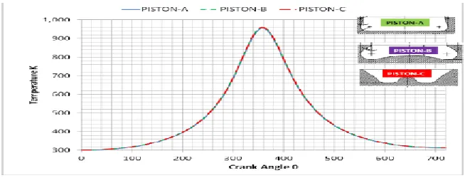
6.1 Pressure and temperature
The graphs Fig 5 and 6 shows pressure
distribution, temperature distribution are
plotted against the time step for various
cases. Note that each increment of a time
step is equals to an increment of 0.25° of
P a g e | 1469 degrees and the maximum pressure reaches
at 360 degree. At the start of combustion
after the ignition delay there is a sudden
change of slope of the p-θ curve. The
pressure rises rapidly for a few crank angle
degrees, and then moves slowly towards a
peak value. The Maximum pressure and end
of compression stroke is 60 bars and
temperature is 980 K.
Figure Pressure Vs. crank angle
Figure Pressure Vs. crank angle
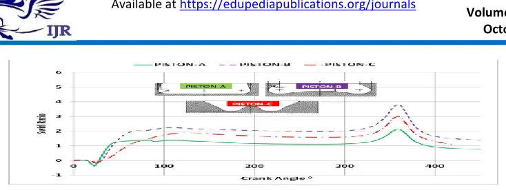
Swirl and Tumble ratio inside the
cylinder
Swirl and tumble ratios are generally
defined as the ratio of the angular
momentum of the in cylinder flow about
each of the three orthogonal axes. It is
normalized against the same gas rotating as
solid body the same axes at crank speed.
The usual method for determining these
ratio is, first the centre of the combustion
chamber is determined. Then the X, Y and Z
are dined with the origin of the centre of the
mass. The Z axis is defined as being parallel
to the line of piston motion. The Y axis is
defined as perpendicular to Z and parallel to
central axis of the inlet manifold. Finally,
the X axis is defined as perpendicular to Z
Figure Swirl ratios for different piston configurations
CONCLUSION:
It is the motivation behind the development
of any internal combustion engine in the
first place fuel efficiency and emissions
requirements. This requires adjustment
operations in the cylinder flow, the mixture
formation and combustion. optimal design
for a container dose / exhaust port, valves
and pistons is essential to meeting the above
requirements. The use of computational
fluid dynamics (CFD), along with
optimization tools can help shorten the cycle
time optimal design. The traditional
approach of experiments using flow bench
testing is very expensive and a waste of
time. Moreover CFD allows penetration into
the small details that would not capture flow
through flow bench tests. Air movement
inside the intake manifold is one of the most
important factors engine and emission
control performance of multi-cylinder diesel
engines. And therefore the study of literature
is a spiral vortex eat multiple combination.
amplifying piston geometry air movement at
the end of the compression stroke. In this
project work, research and internal flow in
the combustion chamber of the diesel
calculation for different property settings
piston engines. The solution to the equations
governing the unsteady flow,
three-dimensional, compressible, and turbulent
two RNG model equation ε k to watch the
complexity of the geometry and movement
of fluids.general flow field was examined
within the combustor and different
quantities, such as pressure, speed
distribution, swirl and tumble dry
proportions for the three types of pistons.
Swirl and rotate proportions can be obtained
very accurately, for both production and
search engines by using computational fluid
dynamics. Comparative summary is as
follows:
1. piston by creating a spiral of increasing
piston within the cylinder C.
2. piston provides a higher volumetric
efficiency. This is achieved by improving
the volumetric efficiency facing the piston
C.
3. kinetic energy of the piston C provides
the highest with problems and find the x and
P a g e | 1471 4. Piston and provide relatively low
proportion turbulence, the lower the
turbulent kinetic energy and a lower
volumetric efficiency
REFERENCES
[1] Aita S, Tabbal A, Munck G,
Montmayeur N, Takenaka Y, Aoyagi Y, et
al. . Numerical simulation of swirling
portvalve- cylinder flow in Diesel engine.
SAE 910263, 1991
[2] Benny Paul1, V. Ganesan, Flow field
development in a direct injection diesel
engine with different manifolds,
International Journal of Engineering,
Science and Technology Vol. 2, No. 1,
2010.
[3] Celik I, Yavuz I, Smirnov A. Large eddy
simulations of in-cylinder turbulence for
internal combustion engines: A Review. Int
J Engine Res 2001;2(2):119–48.
[4] Chen A, Veshagh A, Wallace S. Intake
flow predictions of a transparent DI Diesel
engine. SAE 981020, 1998.
[5] Dillies B, Ducamin A, Lebrere L, Neveu
F. Direct injection Diesel engine simulation:
a combined numerical and experimental
approach from aerodynamics to combustion.
SAE 970880, 1997
[6] F. Payri , J. Benajes, X. Margot , A. Gil,
CFD modeling of the in-cylinder flow in
direct-injection Diesel engines,
CMT-MotoresT_ermicos, Universidad
Polit_ecnica de Valencia, Camino de Vera