Fuzzy LogicController based
MultilevelSTATCOM for High Power
Application
Guraja Nage ndra Babu
M-tech Student Scholar
Department of Electrical & Electronics Engineering, Nova EngineeringCollege and technology, jupudi,
Ibrahimpatnam, Krishna (Dt); A.P, India.
A.Kasim Vali
Associate professor
Department of Electrical & Electronics Engineering, Nova EngineeringCollege and technology, jupudi,
Ibrahimpatnam, Krishna (Dt); A.P, India.
Abstract-In this paper, in order to obtain VAR compensation multi-level inverter topology which is based on cascaded two level inverter is proposed. Through the open end windings of three phase transformer standard two level inverters are connected in cascade. In order to obtain four level operation the DC link voltages of the inverters are regulated. A good number of multilevel inverter topologies have been proposed during the last two decades. Although different multilevel inverter exists, Cascade Multilevel Inverter (CMI) is one of the productive topology from multilevel family. In reality, on comparing with other multilevel based topologies, CMI feature a high modularity degree because each inverter can be seen as a module with similar circuit topology, control structure, and modulation. Static var compensation by cascading conventional multilevel/two level inverters is an attractive solution for high-power applications. The topology consists of standard multilevel/two level inverters connected in cascade through open-end windings of a three-phase transformer. One of the advantages of this topology is that by maintaining asymmetric voltages at the dc links of the inverters, the number of levels in the output voltage waveform can be increased. This improves Power quality of the system. Therefore, overall control is simple compared to conventional multilevel inverters.The proposed concept can be applied to fuzzy controlled system for better performance by using Matlab/Simulation software.
Index Term s —DC-link voltage balance, multilevel inverter, Power quality (PQ), static compensator (STATCOM).
I. INTRODUCTION
The rapid growth in electrical energy use, combined with demand for low cost energy, has gradually led to the development of generation sites remotely located from the load center. The generation of bulk power at remote locations necessitates the use of transmission line to connect generation sites to load centers. With long distance ac power transmission and load growth, active control of reactive power is indispensable to stabilize the power syste m and to maintain the supply voltage [1-2]. The static synchronous compensator (STATCOM) using
voltage source inverters has been accepted as a competitive alternative to the conventional Static VAr compensator (SVC) using thyristor-controlled reactors STATCOM functions as a synchronous voltage source. It can provide reactive power compensation without the dependence on the ac system voltage [3]. By controlling the reactive power, a STATCOM can stabilize the power system, increase the maximum active power flow and regulate the line voltages. Faster response makes STATCOM suitable for continuous power flow control and power system stability improvement. The interaction between the AC system voltage and the inverter-composed voltage provides the control of the STATCOM var output [4] [5]. When these two voltages are synchronized and have the same amplitude, the active and reactive power outputs are zero.
developed [7]-[9]. They are multiple switching elements in one leg of an inverter, series connected inverter, and parallel connected inverters. Among these various multilevel topologies, the cascaded multilevel inverter can imple ment a high number of levels with ease. The modular structure and the ease of redundant operation are also advantages [10].
In this paper, a static var compensation scheme is proposed for a cascaded two-level inverter-based multilevel inverter. The topology uses standard two-level inverters to achieve multilevel operation. The dc-link voltages of the inverters are regulated atasymmetrical levels to obtain four-level operation. To verify the efficacy of the proposed control strategy, the simulation study iscarried out for without fuzzy and with fuzzy [11-12].
II. STATCOM CONFIGURATION
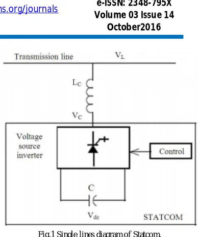
The basic operating configuration of a STATCOM is given in Fig 1. It consists of a voltage source inverter (VSI), dc sideequivalent capacitor(C) with voltage Vdc on it and a coupling reactor (LC).[2] STATCOM is a primary shunt device ofthe FACTS family, which uses power electronics to control power flow and improve voltage stability on power system[3]. The STATCOM regulates voltage at its terminals by controlling the amount of reactive power injected into or absorbed from the power system. For purely reactive power flow in three phase voltages of the STATCOM must be maintained in phase with the system voltages [4]. The variation of reactive power is performed by means of a VSCconnected through a coupling reactor or transformer .The VSC uses forced commutated power electronics devices(MOSFET or IGBT's) to synthesize the voltage from a dc voltage source. [3]The operating principle of STATACOM isexplained in Fig.1. It can be seen that if Vc>Vs then the reactive current flows from the converter to the ac systemthrough the coupling transformer by injecting reactive power to the ac system. On the other hand, if V C< V S thencurrent flows from ac system to the converter by absorbing reactive power from the syste m. 6Finally, if VC= VS then there is no exchange of reactive power.
Fig.1 Single lines diagram of Statcom.
III. Cascade d Two-Level Inverte r-Base d Multilevel STATCOM.
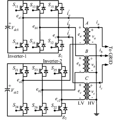
Fig. 2 shows the circuit topology of the cascaded two-level inverter-based multitwo-level STATCOM using standard two-level inverters. The inverters are connected on the low-voltage (LV) side of the transformer and the high-voltage (HV) side is connected to the grid. The dc-link voltages of the inverters are maintained constant and modulation indices are controlled to achieve the required objective. The proposed control scheme is derived from the ac side of the equivalent circuit which is shown in Fig.3. In the figure, ′, ′ and ′are the source voltages referred to LV side of the transformer ra, rb, and rc are the
resistances which represent the losses in the transformer and two inverters, and are leakage inductances of transformer windings, and are the output voltages of inverters 1 and 2, respectively. Are the leakage resistances of dc-link capacitors and, respectively. Assuming and applying KVL on the ac side, the dynamic model can be derived using as
(1) Equation (1) represents the mathematical model of the cascaded two-level inverter-based multilevel STATCOM in the stationary reference frame. This model is transformed to the synchronously rotating reference frame. The d-q axes reference voltage components of the converter and are controlled as
(3) Where v′is the -axis voltage component of the ac source
and i′ , i′are - axes current components of the cascaded
inverter, respectively. The synchronously rotating frame is aligned with source voltage vector so that the -component of the source voltagev′is made zero. The
control parameters and are controlled as follows:
(4) The -axis reference current is ∗ obtained as
(5) Where ∗ , ∗ and are the reference and actual dc-link voltages of inverters 1 and 2, respectively. The q-axis reference current ∗is obtained either from an outer voltage regulation loop when the converter is used in transmission-line voltage support [5] or from the load in case of load compensation.
A 100Mvar STATCOM device is connected to the 230-kV (L-L)grid network. Fig.2 shows the single line diagram representingthe STATCOM and the host sample grid network. The feedingnetwork is represented by a thevenin equivalent at (bus B1) wherethe voltage source is represented by a kV with 10,000 MVA shortcircuit power level with a followed by the transmission line connected to bus B2. The STATCOM device comprises the voltagesource converter-cascade model connected to the host electricgrid. 7-level is chosen here for STATCOM. It is connected to thenetwork through the coupling transformer. The dc link voltage isprovided by the capacitor C, which is charged from the ac network. The decoupled current control system ensures full dynamicregulation of the bus voltage and the dc link voltage.
Figure 2.Single Line Diagram Representing STATCOM.
At the time of starting the source voltage is such that theSTATCOM is inactive. It neither absorbs nor provides reactivepower to the network. The following load sequence is tested andresults are taken.
Fig.3. Cascaded two-level inverter-based multilevel STATCOM
Fig.4.Equivalent circuit of the cascaded two-level inverter-based multilevel STATCOM.
A. Control strategy
The control block diagram is shown in Fig.5. The unit signals and are generated from the phase-locked loop (PLL) using three-phase supply voltages. The converter currents (i′ , i′ ,i′) are transformed to the synchronous
rotating reference fra me using the unit signals. The switching frequency ripple in the converter current components is eliminated using a low-pass filter (LPF). From (v∗ + v∗ ) and i∗loops, the controller generates – axes reference voltages,e∗ and e∗for the cascaded
inverter. With these reference voltages, the inverter supplies the desired reactive current i∗and draws required
active current (i ) to regulate total dc-link voltage v∗ +
values. Hence, additional control is required to regulate individual dc-link voltages of the inverters.
Fig.5.Control block diagram.
B. DC link balance controller
The resulting voltage of the cascaded converter can be given as , where and .The active power transfer between the source and inverter depends on and is usually small in the inverters supplying var to the grid [1]. Hence, can be assumed to be proportional to eq.
Therefore, the q-axis reference voltage component of inverter-2 ∗ is derived to control the dc-link voltage of inverter-2 as
(6) The q-axis reference voltage component of inverter-1
∗ is obtained as
(7) The dc-link voltage of inverter-2 is controlled at 0.366 times the dc-link voltage of inverter-1 [9]. It results in four-level operation in the output voltage and improves the harmonic spectrum.
C. Unbalanced conditions
Network voltages are unbalanced due to asymmetric faults or unbalanced loads. As a result, negative-sequence voltage appears in the supply voltage. This causes a double supply frequency component in the dc-link voltage of the inverter. This double frequency component injects the third harmonic component in the ac side. Moreover, due to sequence voltage, large negative-sequence current flows through the inverter which may
cause the STATCOM to trip. Therefore, during unbalance, the inverter voltages are controlled in sucha way that either negative-sequence current flowing into the inverter is eliminated or reduces the unbalance in the grid voltage. In the latter case, STATCOM needs to supply large currents since the interfacing impedance is small. This may lead to tripping of the converter.
The negative-sequence reference voltage components of the inverter ∗ and ∗ are controlled similar to positive-sequence components in the negative synchronous rotating frame as
(8)
(9)
IV. Control Sche me for STATCOM
To regulate the system voltage and reactive power compensationPI control is employed. To enhance the transient stability fuzzycontrol is employed.
A.Fuzzy Control for STATCOM
Figure.6. Fuzzy logic control system of STATCOM.
Seven linguistic variables are defining for AC voltage and change in AC voltage, which ranges from –1 to +1. The input signal foe supplementary control system is similar to AC bus voltage controller functions. Fig 7 shows the me mbership function for signal of AC and DC voltage regulator
Figure.7. Membership functions for signal of AC and DC voltage regulator.
V.MATLAB/SIMULINK RESULTS
Figure.8.Matlab/Simulink Model ofCascaded Two-Level Inverter-Based Multilevel STATCOM without Fuzzy.
Fig.9.Reactive power control Source voltage and inverter current.
Figure.10.Reactive power control DC-link voltages of two inverters.
Figure.12.Harmonic spectrum of current without fuzzy.
Figure.13.Harmonic spectrum of current with fuzzy.
VI.CONCLUSION
A simple STATCOM scheme using a cascaded two-level inverter-based multilevel inverter is presented in this paper. The proposed topologies have two VSI based two level inverters are connected in cascade through open-end windings of a three-phase transformer and filter elements. Converter fed dc-link voltages is regulated at different levels to obtain four-level operation. Fuzzy Control is employed to enhance the transient stability. It is inferred from the graph that real power improved using PI controller and transient is reduced using fuzzy control. The performance of the scheme is validated by simulation and experimentations under balanced and unbalanced voltage conditions. Further, the cause for instability when there is a change in reference current is investigated. The dynamic model is developed and transfer functions are derived. System behavior is analyzed for various operating conditions. From the analysis, it is inferred that the syste m is a non minimum phase type, that is, poles of the transfer function always lie on the left half of the -plane. However, zeros shift to the right half of the -plane
for certain operating conditions. For such a system, oscillatory instability for high controller gains exists.
REFERENCES
[1] N. G. Hingorani and L. Gyugyi, Understanding FACTS. Delhi, India: IEEE, 2001, Standard publishers distributors.
[2] B. Singh, R. Saha, A. Chandra, and K. Al-Haddad, “Static synchronous compensators (STATCOM): A review,” IET Power Electron., vol. 2, no. 4, pp. 297–324, 2009.
[3] H. Akagi, H. Fujita, S. Yonetani, and Y. Kondo, “A 6.6-kV transformer less STATCOM based on a five-level diode-clamped PWM converter: System design and experimentation of a 200-V 10-kVA laboratory model,” IEEE Trans. Ind. Appl., vol. 44, no. 2, pp. 672–680,
Mar./Apr. 2008.
[4] A. Shukla, A. Ghosh, and A. Joshi, “Hysteresis current control operation of flying capacitor multilevel inverter and its application in shunt
compensation of distribution systems,” IEEE Trans. Power Del., vol. 22, no. 1, pp. 396–405, Jan. 2007.
[5] H. Akagi, S. Inoue, and T. Yoshii, “Control and performance of a transformer less cascaded PWM STATCOM with star con figuration,” IEEETrans. Ind. Appl., vol. 43, no. 4, pp. 1041–1049, Jul./Aug. 2007. [6] Y. Liu, A. Q. Huang, W. Song, S. Bhattacharya, and G. Tan, “Small signal model-based control strategy for balancing individual dc capacitor voltages in cascade multilevel inverter-based STATCOM,” IEEE Trans. Ind. Electron., vol. 56, no. 6, pp. 2259–2269, Jun. 2009. [7] H. P. Mohammadi and M. T. Bina, “A transformer less medium-voltage STATCOM topology based on extended modular multilevel converters,” IEEE Trans. Power Electron., vol. 26, no. 5, pp. 1534– 1545, May 2011. [8] X. Kou, K. A. Corzine, and M. W. Wielebski, “Overdistention operation of cascaded multilevel inverters,” IEEE Trans. Ind. Appl., ol. 42, no. 3, pp. 817–824, May/Jun. 2006. [9] K. K. Mohaptra, K. Gopakumar, and V. T. Somasekhar, “A harmonic elimination and suppression scheme for an open-end winding induction motor drive,” IEEE Trans. Ind. Electron., vol. 50, no. 6, pp. 1187–1198, Dec. 2003.