Copyright to IJIRSET www.ijirset.com 4547
EXPERIMENTAL STUDY ON THE
EFFECT OF CUTTING PARAMETERS ON
SURFACE FINISH OBTAINED IN CNC
TURNING OPERATION
B.
TULASIRAMARAO
1, Dr.K.SRINIVAS2 ,Dr. P RAM REDDY3, A.RAVEENDRA4, Dr.B.V.R.RAVI KUMAR 5 Asst. prof, Dept of Mech Engg, Malla Reddy institute of engineering technology, Secunderabad AP, INDIA 1.Professor, Dept of Mech Engg, RVR&JC college of Engineering, Guntur, AP, INDIA 2
Professor ,Dept of Mech Engg , Dean Academics, Malla Reddy College Of Engineering & Technology. Secunderabad , AP, INDIA3
Assoc. professor, Dept of Mech Engg, Malla Reddy Engineering Coolege, Secunderabad AP, INDIA 4 Professor, Dept of Mech Engg, VNRVJIET, Hyderabad, AP, INDIA5
ABSTRACT: Thispaperdeals with finding optimal control parameters to get the minimum Surface roughness. It
considers the analysis of effect of the process parameters, cutting speed, feed rate and depth of cut on cutting forces during turning operation. Machining is the process of removing the excess material from the work piece or unwanted material from the work piece using cutting tool. Surface finish obtained in machining process depends upon so many factors like work material, tool material, tool geometry, machining conditions, cutting fluids used and feed rate etc. In this experimental work it is planned to study the effect of process parameters on surface finish obtained in the machining process of materials like stainless steel and aluminum.
Keywords: Cutting speed, feed, depth of cut and surface roughness
I. INTRODUCTION
A . Metal cutting
Metalworking is the process of working with metals to create individual parts, assemblies, or large scale structures. The term covers a wide range of work from large ships and bridges to precise engine parts and delicate jewelry. It therefore includes a correspondingly wide range of skills, processes, and tools.
Cutting is a collection of processes wherein material is brought to a specified geometry by removing excess material using various kinds of tooling to leave a finished part that meets specifications. The net result of cutting is two products, the waste or excess material, and the finished part. If this were a discussion of woodworking, the waste would be sawdust and excess wood. In cutting metals the waste is chips and excess metal. These processes can be divided into chip producing cutting, generally known as machining. Burning or cutting with an oxy fuel torch is a welding process not machining.
Copyright to IJIRSET www.ijirset.com 4548 Chip producing processes most commonly known as machining.
Burning, a set of processes which cut by oxidizing a kerf to separate pieces of metal.
Specialty processes.
There are many technologies available to cut metal, including: • Manual technologies: saw, chisel, shear or snips.
• Machine technologies: turning, milling, drilling, grinding, sawing.
• Welding/burning technologies: burning by laser, oxy-fuel burning, and plasma.
B. Turning
Turning is a machining process in which a cutting tool, typically a non-rotary tool bit, describes a helical tool path by moving more or less linearly while the work piece rotates. The tool's axes of movement may be literally a straight line, or they may be along some set of curves or angles, but they are essentially linear (in the nonmathematical sense). Usually the term "turning" is reserved for the generation of external surfaces by this cutting action, whereas this same essential cutting action when applied to internal surfaces (that is, holes, of one kind or another) is called "boring". Thus the phrase "turning and boring" categorizes the larger family of (essentially similar) processes. The cutting of faces on the work piece (that is, surfaces perpendicular to its rotating axis), whether with a turning or boring tool, is called "facing", and may be lumped into either category as a subset.
C. Cutting parameters
In turning, the speed and motion of the cutting tool is specified through several parameters. Out of the many parameters affecting the surface roughness of a metal these parameters are selected for each operation based upon the work-piece material, tool material, tool size, and more.
Spindle speed - The rotational speed of the spindle and tool in revolutions per minute (RPM). The spindle speed is equal to the cutting speed divided by the circumference of the tool.
Depth of cut -Cutting speed and feed rate come together with depth of cut to determine the material removal rate, which is the volume of work-piece material (metal, wood, plastic, etc.) that can be removed per time unit.
Feed rate - The speed of the cutting tool's movement relative to the work-piece as the tool makes a cut. The feed rate is measured in inches per minute (IPM) and is the product of the cutting feed (IPR) and the spindle speed (RPM).
II. EXPERIMENTAL PROCEDURE
Material: High speed steel (HSS) cutters are the least-expensive and shortest-lived cutters. Cobalt steel is an
improvement on HSS and generally can be run 10% faster. Carbide tools are more expensive than steel, but last longer, and can be run much faster, so prove more economical in the long run. HSS tools are perfectly adequate for many applications. The progression from HSS to cobalt steel to carbide could be viewed as very good, even better, and the best.
Diameter: Larger tools can remove material faster than small ones, therefore the largest possible cutter that will fit in the job is usually chosen. The radius of the cutter must be less than or equal to the radius of the smallest arc.
Copyright to IJIRSET www.ijirset.com 4549
The experimental procedure is carried out in the following five steps:
STEP 1: The raw material (metal rods) is fed into the CNC Turning lathe Machine. STEP 2: The Metal rods are magnetically clamped in the machine
STEP 3: The program is written in the computer console according to the required cutting parameters i.e. Cutting Speed, Depth of Cut and Feed Rate.
STEP 4: The process of turning has been done in the following three cases
Varying speed while keeping the Depth of Cut and Feed Rate constant
Varying Feed Rate and keeping the Spindle Speed and Depth of Cut constant.
Varying Depth of Cut while keeping the Spindle Speed and Feed Rate constant STEP 5:
5.1 FOR STAINLESS STEEL:
Case 1: Table 5.1.1: Varying Spindle speed
S.no Spindle
speed
Depth of Cut
Feed Rate
Ra Value
Copyright to IJIRSET www.ijirset.com 4550
Graph 5.1.1 Spindle speed vs surface finish
Case 2:
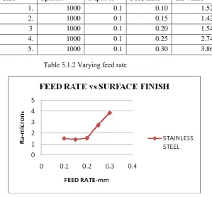
Table 5.1.2 Varying feed rate
Graph 5.1.2 Feed rate vs surface finish
S.no Spindle
Speed
Depth of Cut
Feed Rate Ra Value
Copyright to IJIRSET www.ijirset.com 4551
Case 3: Table 5.1.3 Varying Depth of Cut
Graph 5.1.3 Depth of cut vs surface finish 5.2 FOR ALUMINIUM
Case 1: Table 5.2.1 Varying Spindle Speed
S.No Spindle
Speed
Depth of Cut
Feed Rate
Ra Value
1. 1000 0.1 0.1 1.40 2. 1000 0.2 0.1 1.10 3. 1000 0.3 0.1 1.12 4. 1000 0.4 0.1 1.12 5. 1000 0.5 0.1 1.42
s.no Cutting
Speed
Depth of Cut
Feed Rate
Ra Value
Copyright to IJIRSET www.ijirset.com 4552
−Graph 5.2.1 spindle speed vs surface finish
Case 2: Table 5.2.2 Varying Feed Rate
S.No Cutting
Speed
Depth of Cut
Feed Rate
Ra Value
Copyright to IJIRSET www.ijirset.com 4553
Graph 5.2.2 Feed rate vs surface finish
Case 3: Table 5.2.3 Varying Depth of Cut
S.No Cutting
Speed
Depth of Cut
Feed Rate
Ra Value
Copyright to IJIRSET www.ijirset.com 4554
Graph 5.2.3 Depth of cut vs surface finish III. CONCLUSION
Thus in our project, we have performed a detailed experiment process of the cutting parameters influencing the surface roughness on a metal after CNC Turning.
In our work process we have identified the values of the optimum cutting parameters to get the minimum Surface roughness.
We have experimented with various combinations of the three cutting parameters i.e. Spindle Speed, Depth of Cut and Feed Rate.
We have arrived on a conclusion that the minimum surface roughness in stainless steel is obtained when the Spindle speed is (1200 rpm approx.), Depth of cut and Feed Rate are minimum (i.e 0.2 mm and 0.15 mm respectively).
In case of aluminum the minimum surface is obtained when the spindle speed is (800 rpm approx), Depth of cut and Feed Rate are minimum (i.e 0.3 mm and 0.15 respectively).
Note: As the surface roughness increases the surface finish decreases.
REFERENCES
1) Indrajith Mukharji,Pradip Kumar Ray(2006) ’A review of optimisation techniques in metal cutting process’Computers and Industrial engg.50,15-34.
2) G.Boothroyd,’Fundamentals of machining and machine tools’ 1sted,Scrapta Book Company’.
3) W. E. Biles, James J. Swain, “Optimization and industrial experimentation”, 1980, John Wiley & sons, New York.
4) Muammer Nalbant, Hasan Gokkaya, and Ihsan Toktas¸2007. Comparison of Regression and Artificial Neural Network Models for Surface Roughness Prediction with the Cutting Parameters in CNC Turning. Modelling and Simulation in Engineering. pp. 1- 14, doi:10.1155/2007/92717.
5) Oktem. H., Erzurumlu. T., Kurtaran. H., 2005. Application of response surface methodology in the optimization of cutting conditions for surface roughness. J. Mater. Process. Technol. Vol.170, pp. 11–16
Copyright to IJIRSET www.ijirset.com 4555 BIOGRAPHY
1. B Tulasiramarao is a faculty member in mechanical engineering and pursuing phd in
mechanical engineering. He is pursuing in the field of metal cutting in JNTU, Hyderabad from past 3years and has three other research publications in this field, likely to submit in one year
2. Dr.K.Srinivas the other is a professor in mechanical engineering for the past 15 years he is
in the research field, His area of research includes metal cutting and thermal engineering. . He is working as a Professor in the Department of Mechanical Engineering, .R.V.R&J.C .College of Engg. ,Guntur, India. And he has published more than 25 research papers in various National/International Journals and Conference proceedings.
3. Dr. P.Ram Reddy he is a professor in mechanical engineering and in the teaching field for the
past 45 years . He has successfully guided 11 PH.D.S and has 104 research papers to his credit . He is a recipient of engineer of the year 2010 awarded by Govt. of A.P and Institute of engineers India ,Hyderabad Chapter.
4.Mr.Raveendra Akunuru is born in India, Andhra Pradesh. He received B.Tech (Mechanical)
degree from R.E.C (Now National Institute of Technology) ,Warangal , Andhra Pradesh, India and M.Tech (Production Engineering) degree from Visveswaraya Technological University Belgaum, Karnataka, India. He is pursuing his doctoral study in Joining Processes at JNTU , Hyderabad, India. He is working as Associate Professor in Malla Reddy Engineering College, Secunderabad. He has 5 years of Industrial experience along with 10 years of Teaching experience. His research interests in Pulsed Current TIG Welding. He is a life member of Indian Welding Society.
5.Dr.B.V.R.Ravi Kumar received M.Tech (Design & Production Engineering) from R.E.C (Now