Performance Analysis of SMQW SOA Based
On Optical Confinement Factor
Nipu R. Barai
1, Rinku Basak
2M.Sc. Student, Dept. of Electrical and Electronic Engineering, American International University-Bangladesh, Dhaka,
Bangladesh1
Assistant Professor and Head of Graduate Program, Faculty of Engineering, American International
University-Bangladesh, Dhaka, Bangladesh2
ABSTRACT: Study of the dependency of optical confinement factor (OCF) on the structure parameters of symmetrical multiple quantum well (SMQW) semiconductor optical amplifier (SOA) is important for better design of SOA devices. This paper presentsan overall structure of a SMQWSOA, and dependency analysis of OCF on different structure parameters.The effects of number of well layers, well thickness and barrier thickness of SMQW SOA on OCF are investigated through simulations performed using MATLAB.The simulation results show that OCF of a SMQW SOA increases with increasing number of quantum well layers and well layer thickness. However, the change in barrier thickness doesn‟t have significant impact on the OCF.Thesimulation resultsalso indicate that with appropriate number of well layers and well layer thickness, it is possible to obtain a better OCF.The findings of this study can be used for creating more efficient and stable SMQW SOA design.
KEYWORDS: Symmetrical Multiple Quantum-well, Semiconductor Optical Amplifier, Optical Confinement Factor.
I.INTRODUCTION
Semiconductor optical amplifier, referred to as SOA, is used for many applications in all-optical systems including amplification of the optical signal without converting it into electrical signal [1].SOA is becoming popular because it is suitable for integration and it can be used as functional devices.In addition, it can operate in a wide bandwidth region. There are many types of SOA depending on the construction of its active region (e.g., multiple quantum well (MQW) SOA,travelling wave (TW) SOA, quantum dot (QW) SOA, gain clamped (GC) SOA)[2-3].Based on the quantum well layers MQW SOA can be divided into two types,thesymmetrical MQW SOA and the asymmetrical MQW SOA. Symmetrical multiple quantum well (SMQW) SOAis the focus point of this paper. The structure of SMQW SOA is similar to that of a semiconductor laser. The main difference is in the anti-reflective mirror (or coating) on both of its facets [4]. The fabrication of the active region is done by loading well and barrier layers. These layers are grown using different types of growth technique such as molecular beam epitaxy (MBE), organo-mettalic vapour epitaxy (OMVPE) [2]. The advantages of using SMQW SOA are its ability to perform at original to ultra-long wavelength band, higher saturation output, ultrafast gain recovery, low noise operation, control polarization sensitivity, compactness, and cost-effectiveness [5-7]. Some of the drawbacks include narrower full width half maximum (FWHM) gain bandwidth and complexity in growing layers [8-9].
II. THEORETICAL BACKGROUND
A simplified schematic structure of 3D SMQW SOA is shown in Fig. 1. It shows the wells and barrier layers of the active region, as well as the cladding layers. In this case, it is considered that the active region length is equal to the cavity length, and the taper length, Lt, isequal to zero. The length of the active region (L) is given by [11],
L= Lc (1)
where, Lc is the cavity length. The amplifier is designed with negligible facet reflectivity to ensure a single pass.
(a) (b)
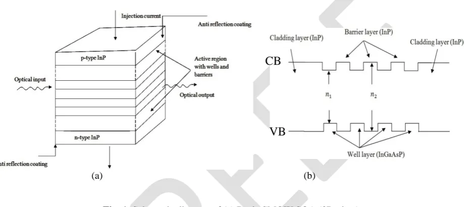
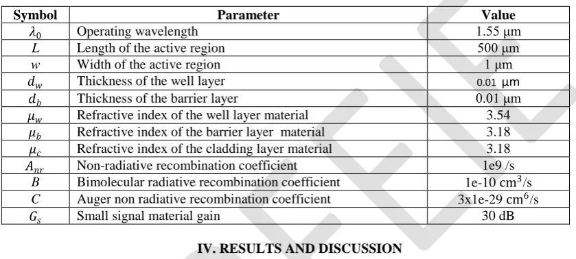
Fig. 1. Schematic diagram of (a) Basic SMQW SOA (3D view).
Injection current direction and power direction is shown. Length of the active region is considered to be equal to the length of the cavity region and the taper length is ignored. The active region is sandwiched between the two doped cladding layers and the number of wells and barrier layers can be varied according to the need of the application. (b) Basic structure of the conduction band (CB) and valence band (VB) of a SMQW SOA where the cladding and barrier material is InP and the well material is InGaAsP. Here 𝑛1 and 𝑛2 are refractive indices of the well and barrier layers and (𝑛1>𝑛2).
The injection current (I) is related to the carrier density (n) by [12],
I= qVn
τc (2)
where, q is the electron charge, V is the volume of the active region, n is the carrier density and τc is the carrier lifetime. Carrier lifetime is non linearly dependent to the Auger nonradiative recombination in InGaAsP material system as [13],
τc= 1
Anr+Bn +Cn2 (3)
where, Anr is nonradiative recombination coefficient, B is the bimolecular radiative recombination coefficient and C is the Auger non radiative recombination coefficient.
The saturation power dependency on the material parameters can be expressed as [12],
Psat = (hc0wd)/(λ0Γa)[Anr + B n0+
α+ ln GsΓ
Γa + C(n0+
α+(ln Gs/Γ) Γa )
2] (4)
CB
n = n0+α+(ln Gs/Γ)
Γa (5)
Gs = exp[(gs − α)L] (6)
where, n is the carrier density, n0 is the carrier density for transparency, Γ is the optical confinement factor, α is the insertion loss, a is the material gain co-efficient, h is the Planck‟s constant, c0 is the speed of light in vaccum and λ0 is 1.55 μm. OCF is related to the active layer parameters and refractive indices of the layer materials [2].
Γ= γNwdw
Nwdw+Nbdb (7)
where, co-efficient γ is related to the effective refractive index by,
γ= 2𝜋2 N
wdw+ Nbdb 2( μeff2−μ
c2
λ02 ) (8)
where,μeff is the effective refractive index. This is also related to the refractive indices and the layer parameters by [12],
μeff = Nwdwμw+Nbdbμb
Nwdw+Nbdb (9)
where, Nw is the number of wells, Nb is the number of barriers denoted by (Nw− 1), dw is the well thickness, db is the barrier thickness, μw is the refractive index of the well layer material (InGaAsP in this case), μb is the refractive index of the barrier material ( here,InP). Substitutionof the value of equation (9) into equation (8) provides,
γ= 2𝜋2 N
wdw+ Nbdb 2(
N w d wμw +N b d bμb 2
N w d w +Nb db −μc2
λ02 ) (10)
Now, for SMQW SOA the relation of optical confinement factor with the structure parameters can be expressed as,
Γ=
2𝜋2 Nwdw+Nbdb 2(
N w d wμw +N b d bμb
N w d w +N b db 2
−μb2 λ02
)Nwdw
Nwdw+Nbdb (11)
For single QW, the optical confinement factor is expressed as,
Γsqw=
2𝜋2Nw2Nb2(μeff2−μb2)
λ02 (12)
OCF is the ratio of light intensity within the active region to the total light intensity. It is defined as „Γ‟. As the name indicates, the light is needed to be confined in the active region for the operation and not being scattered or absorbed by other layers. Therefore, a higher OCF is required. Usually in laser operation the value of OCF is kept 0.4 or more for a stable operation. In SMQW SOA, OCF of 0.3 to 0.6 is acceptable for better performance. In large modulation bandwidth systems, higher OCF is required [15-16]. OCF depends on the molar fraction and thus related to the material composition [2] which leads to the quantum well and material well materials.
III.SIMULATIONS
InP/InGaAsP system. The most important criteria for selection of well layers and barrier layers arethat the band-gap energy of the well layer (InGaAsP) is lower than the band-gap energy of the barrier layer (InP), and the refractive index is greater for the well material. The lattice parameters are also required to be matched(5.8694 Å in this case) [10].The composition of the compounds expressed in the form of In1−xGaxAsyP1−y [10].Compositions including the molar fraction values are not provided in details here.The values of various parameters in the simulations are provided in Table 1 [14].
TABLEI
SMQWSOASTRUCTUREANDMATERIALPARAMETERS
Symbol Parameter Value
𝜆0 Operating wavelength 1.55 μm
L Length of the active region 500 μm
w Width of the active region 1 μm
𝑑𝑤 Thickness of the well layer 0.01 μm
𝑑𝑏 Thickness of the barrier layer 0.01 μm
𝜇𝑤 Refractive index of the well layer material 3.54
𝜇𝑏 Refractive index of the barrier layer material 3.18 𝜇𝑐 Refractive index of the cladding layer material 3.18
𝐴𝑛𝑟 Non-radiative recombination coefficient 1e9 /s
B Bimolecular radiative recombination coefficient 1e-10 cm3/s
C Auger non radiative recombination coefficient 3x1e-29 cm6/s
𝐺𝑠 Small signal material gain 30 dB
IV. RESULTS AND DISCUSSION
The change in OCF is observed for variation of different structure parameters, e.g., number of quantum wells, number of barriers, well layer thickness and barrier layer thickness.Fig. shows the change in OCF due to the variation of the number of well layers between 0 and 20. The results indicate that with the increase in number of well layers, OCF is increased exponentially with the values between 0 and 0.8. Fig. 2 presents the dependency of OCF on increasing number of wells in the active region. For lower number of wells the OCF has a lower value. When the complexity of the growing layers is avoided, and there are limitations in choosing higher number of wells, the SMQW SOA can be designed with lower number of well layers. However, the tradeoff would be lower OCF.
Fig. 2. Variation of OCF with the increasing number of wells. When the number of wells are varied from 0 to 20, the OCF is increased exponentially from 0 to 0.8.
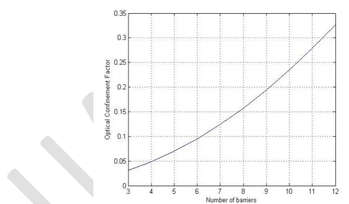
Fig. 3. Variation of OCF with the increasing number of barrier layers. For Nw wells the number of barrier is (Nw− 1).
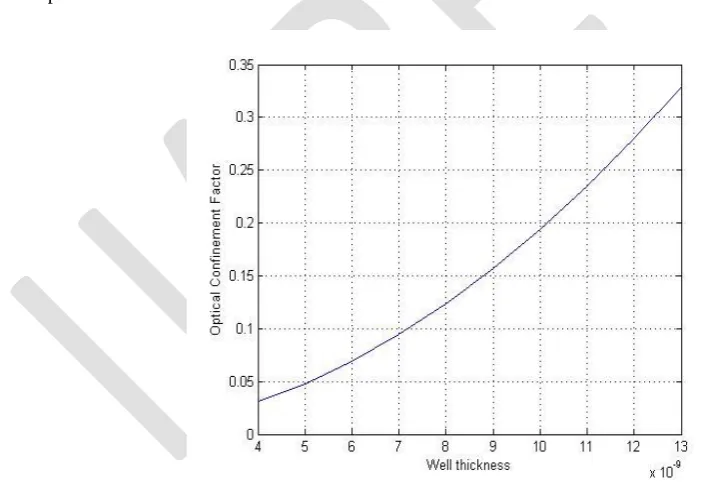
Fig. 4.Variation of OCF with the increasing well thickness in the active region for 4 QWs.
For the well thickness range of 4 nm to 13 nm, 10 and 15 well layered devices are also analyzed. Fig. 5 shows the OCF versus well thickness curve for 10 welled active region SMQW SOA. When the number of barriers is 9, the OCF varies from approximately 0.03 to 0.35 for the well thickness variation from 4nm to 13nm. The range of OCF here is higher than the previous case.
Fig. 5. Variation of
OCF
with the increasing well thickness in the active region for 10 QWs.Fig. 6. Variation of OCF with the increasing well thickness in the active region for 15 QWs.
The results shown in Fig. 4, Fig. 5 and Fig. 6indicate that for the same thickness range (4 nm to 13 nm), SMQW SOA designed with 10 to 15 quantum wells shows higher OCF.
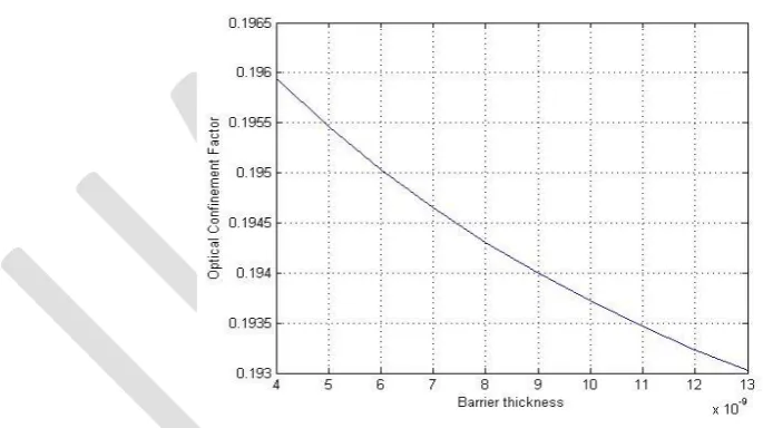
In order to observe the change in OCF for different barrier layer thicknesses, the barrier thickness is varied from 4 nm to 13 nm. The OCF versus barrier thickness graph is determined for both 4 wells and 10 wells. In both of the cases, the OCF shows minor decrement with the increasing barrier thickness. From Fig. 7 it can be established that the OCF does not depend on barrier thickness (for 10 wells). The increase in barrier thickness from 4 nm to 13 nm results in the OCF changes from 0.193 to 0.1965.
Fig. 7. Variation of OCF with the increasing barrier thickness in the active region for 10 QWs.
V.CONCLUSION
or multiple modes), divergence as well as the threshold current conditions [17]. Therefore, OCF is very important while designing a SMQW SOA. A major drawback of using SOA is the pattern effect; however, solutions are available such as using Lyot filter [18].
REFERENCES
[1] M. J. Connelly, “Semiconductor optical amplifiers”, Dordrecht, the Netherlands: Kluwer Academic Publishers, ch.1-3, pp.1-41, 2002. [2] N. K. Dutta, Q. Wang, “Semiconductor optical amplifiers”, 5 Toh Tuck Link, Singapore: World Scientific Publishing Co. Pte. Ltd, ch.1-2,
2006.
[3] J. Bernard and M. Renaud, "Semiconductor Optical Amplifiers",SPIE's OE Magazine, Vol.1, No.1, pp. 36-38, Sep. 2001.
[4] T. Durhuus, B. Mikkelsen, K. E. Stubkjaer, “Detailed Dynamic model for semiconductor optical amplifiers and their crosstalk and intermodulation distortion”, Journal of Lightwave Technology, Vol.10, pp.1056-1064, 1992.
[5] T. Motaweh, P. Morel, A. Sharaiha, M. Guegan, “A Semi-phenomenological model for the material gain of broadband MQW-SOAs”,13th conference of Numerical Simulation of Optoelectronic devices (NUSOD),pp. 43-44, 19-22, 2013.
[6] M. Babaei, S. S. Hosseini, and S. M. Kuchaki, “Improving gain and saturation output power in single-quantum-well semiconductor optical amplifiers”, IEEE Journal of Quantum Electronics, Vol.45, pp.342-347, 2010.
[7] H. J. S. Dorren, X. Yang, D. Lenstra, H. de Waardt, G. D. Khoe, T. Simyama, H. Ishikawa, H. Kawashima, and T. Hasama, “Ultrafast refractive index dynamics in a multiple quantum well semiconductor optical amplifier”, IEEE Photonics tech. letters, Vol.15, No.6, 2003. [8] V. V. Lysak, H. Kawaguchi, and I. A. Sukhoivanov, “Gain spectra and saturation power of asymmetrical multiple quantum well semiconductor
optical amplifiers”, IEE Proc.-Optoelectronic., Vol.152, No.2, 2005.
[9] W. Loh, J. J. Plant, J. Klamkin, J. P. Donnelly, F. J. Odonnell, R. J. Ram , P. W. Juodawlkis, “ Limitations of noise figure in InGaAsP quantum well semiconductor oprical amplifiers”, CLEO and QELS Conference, San Jose, CA, pp.1-2, 2010.
[10] G. H. Olsen, T. Z. Zamerowski, R. T. Smith, E. P. Bertin, "InGaAsPquarternary alloys: composition, refractive index and lattice mismatch", Journal of Electronic Materials, Vol.9, No.6, 1980.
[11] M. J. Connelly, "Wideband Semiconductor Optical Amplifier Steady-State Numerical Model", IEEE Journal of Quantum Electronics, Vol.37, No.3, 2001.
[12] A. A. Al-mfrji, “Saturation Gain Characteristics of Quantum-Well Semiconductor Optical Amplifier”. Nahrain University, College of Engineering J. (NUCEJ), Vol.14, No.2, pp.205-212, 2011.
[13] F. Wang, G. Xia, and Z. Wu, “Numerical study of mode-locked semiconductor optical amplifier fiber ring laser”, J. Optoelectronics and Advanced Materials, Vol.8, No.3, pp.1267-1272, 2006.
[14] A. A. Lobintsov, M. B. Uspenskii, V. A. Shishkin, M. V. Shramenko, and S. D. Yakubovich, “Highly efficient semiconductor optical amplifier for 820-860 nm spectral range”, IEEE J. Quantum Electronics, Vol.40, No.4, 2010.
[15] J. Shimizu, H. Yamada, s. Murata, A. Tomita, M. Kitamura, and A. Suzuki,"Optical Confinement Factor Dependencies of the K factor, Differential Gain, and Nonlinear Gain Coefficient for 1.55um InGaAs/InGaAsP MQW and Strained-MQW Lasers",IEEE Photonics technology letter, Vol.3, No.9, 1991.
[16] Y. Z. Huang, Z. Pan, and R. H. Wu, “Analysis of the optical confinement factor in semiconductor lasers”, Journal of Applied Physics,Vol.79, No.8, 1996.
[17] T. D. Visser, H. Blok, B. Demeulenaere, and D. Lenstra, “Confinement factors and gain in optical amplifiers”, IEEE Journal of Quantum Electronics, Vol.33, No.10, 1997.