of NLFSRs
Elena Dubrova
Royal Institute of Technology (KTH), Forum 120, 164 40 Kista, Sweden {dubrova}@kth.se
Abstract. Non-Linear Feedback Shift Registers (NLFSR) are a generalization of Linear Feedback Shift Registers (LFSRs) in which a current state is a non-linear function of the previous state. The interest in NLFSRs is motivated by their ability to generate pseudo-random sequences which are usually hard to break with existing cryptanalytic methods. However, it is still not known how to construct largen-stage NLFSRs which generate full cycles of 2npossible states. This paper presents a method for generating full cycles by a composition of NLFSRs. First, we show that ann∗k-stage register with periodO(22n)can be constructed from
k n-stage NLFSRs by adding to their feedback functions a logic block of size O(n∗k). This logic block implements Boolean functions representing the set of pairs of states whose successors have to be exchanged in order to join cycles. Then, we show how to join all cycles into one by using one more logic block of sizeO(n∗k2)and an extra time step. The presented method is feasible for generating very large full cycles.
1
Introduction
Non-Linear Feedback Shift Registers (NLFSR) are a generalization of Linear Feedback Shift Registers (LFSRs) in which a current state is a non-linear function of the previ-ous state [1]. The interest in NLFSRs is motivated to a large extent by their ability to generate pseudo-random sequences which are usually hard to break with existing crypt-analytic methods [2]. While LFSRs are widely used in testing and simulation [3], for cryptographic applications their pseudo-random sequences are not secure. The structure of ann-bit LFSR can be easily deduced from 2nconsecutive bit of its sequence by using the Berlekamp-Massey algorithm [4]. Contrary, an adversary might need up toO(2n) bits of a sequence to determine the structure of then-bit NLFSR which generates it [5]. However, while the theory behind LFSRs is well-understood, many fundamental problems related to NLFSRs remain open. One of the most important ones is construct-ing an NLFSR with the maximum period. It is known that ann-stage LFSR has the maximum period of 2n−1 if and only if its characteristic polynomial is primitive [1]. For NLFSRs, no similar property has been found so far. Small NLFSRs with the maxi-mum period can be computed by simulation. However, with today’s processing power, we can simulate NLFSRs of sizen<35 only [6]. This is not enough for cryptographic applications, which require periods larger that 2128[7].
exactly once. It is known that the number of different de Bruijn sequences of ordernis 22n−1−n[8]. An excellent survey of algorithms for generating de Bruijn sequences using shift registers is given in [9]. These algorithms can be classified into two groups.
Algorithms in the first group start from a shift register producing several shorter cycles and then join them into one cycle. Fredricksen [10] have shown how to generate full cycles from a circulating register of lengthnusing 6nbits of storage andntime steps to produce the next state from a current state. The algorithm of Etzion and Lempel [11] generates full cycles from a pure summing register usingn2/4 bits of storage andn time steps to produce the next state. Jansen [12] presented an algorithm for joining state cycles of an arbitrary shift register. This algorithm generates full cycles using 3nbits of storage and at most 4ntime steps for producing the next state from a current state.
A recursive algorithm for generating de Bruijn sequences based on Lempels D-homomorphism was presented by Annexstein [13]. A non-recursive version of this al-gorithm was proposed by Chang et al in [14]. In both alal-gorithms,n-variable Boolean functions generating de Bruijn sequence of ordernare constructed from Boolean func-tions with a smaller number of variables.
Algorithms in the second group start from a shift register with a known period and obtain another shift register with the same period by using cross-join pairs. Different approaches to selecting cross-join pairs have been explored. Fredriksen [15] proposed an algorithm for a class of NLFSRs generating ”prefer one” de Bruijn sequences. In a ”prefer one” de Bruijn sequence, then-tuple(1,a1,a2, . . . ,an−1)precedes then-tuple (0,a1,a2, . . . ,an−1)for alln−1-tuples(a1,a2, . . . ,an−1)except all-0. Dubrova [16] pre-sented a method for constructing NLFSRs with period 2n−1 from maximum-period LFSRs in which the cross-join pairs are determined by a non-linear function added to the LFSR. The number of possible cross-join pairs in maximum-period LFSRs has been derived by Helleseth and Kløve [17].
This paper presents a method for generating full cycles by a composition of NLF-SRs. First, we show how to construct n∗k-stage register with period O(22n) fromk n-stage NLFSRs. We derive Boolean functions representing the set of pairs of states whose successors have to be exchanged in order to join cycles. These functions are added to the feedback functions ofn-stage NLFSRs. We prove that the additional logic can be implemented usingO(n∗k)2-input gates. Then, we show how to join all cycles into one by using one more logic block of sizeO(n∗k2)and an extra time step.
In a full cycle generated by a traditional NLFSR, each current and next state overlap in all but one positions. Inn∗k-stage registers constructed using the presented method, each current and next state overlap in all but kpositions. Therefore, their full cycles differ from the full cycles generated by NLFSRs and their output sequences are not of de Bruijn type.
The paper is organized as follows. Section 2 gives a background on NLFSRs. Sec-tion 3 introduces (n,k)-composed registers. Section 4 analyses properties of (n,k )-composed registers. Section 5 presents an algorithm for constructing registers with
pe-riod O(22∗n) from (n,k)-composed registers. Section 6 presents an algorithm which
2
Preliminaries
Throughout the paper, we use ”⊕” and ”·” to denote addition and multiplication in
GF(2), respectively, and ”+” and ”∗” to denote arithmetic addition and multiplication,
respectively. We usexto denote the complement ofx, defined byx=1⊕x.
Ann-stageNon-Linear Feedback Shift Register(NLFSR) consists ofnbinary stor-age elements, calledstages[1]. Each stagei∈ {1,2, . . . ,n}has an associatedstate vari-able xi∈ {0,1} which represents the current value of the stage. At each clock cycle, the value ofxi+1is transferred toxi, for alli∈ {1,2, . . . ,n−1}. Thefeedback function f(x1,x2, . . . ,xn), computed from the content of thenstages, determines the next value ofxn. Theoutputof an NLFSR is the sequence of bits appearing in its stage 1.
The feedback function f induces the mappingF:{0,1}n→ {0,1}nof type
(x1,x2, . . . ,xn)→(x2,x3, . . . ,xn,f(x1,x2, . . . ,xn)).
Thestateof ann-stage register is a vector of valuesS= (s1,s2, . . . ,sn)∈ {0,1}nof its state variablesx1,x2, . . . ,xn.
Acycleof lengthmof ann-stage register is a vector of states(S0,S1, . . . ,Sm−1)such thatF(Si) =Si+1, fori∈ {0,1, . . . ,m−2}, andF(Sm−1) =S0. Theperiodof a register is the length of its longest cycle1.
A necessary and sufficient condition for an NLFSR to bebranchless[1] is that its feedback function f can be written in the form
f(x1,x2, . . . ,xn) =x1⊕gi(x2, . . . ,xn),
wheregis a Boolean function which does not depend on the variablex1.
Aproduct-termof ann-variable Boolean function is an expression of typex.1·x.2
·. . .·x.k wherex.i is either a variable xi or its complement xi, for 1≤k≤n [18]. A mintermof ann-variable Boolean function is a product-term withk=n. A product-term represents a subspace of ann-dimensional Boolean space, while a minterm represents a point of ann-dimensional Boolean space.
3
Composition of NLFSRs
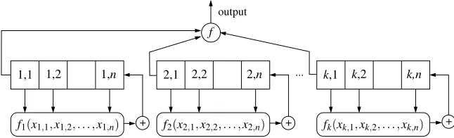
Consider ann∗k-stage register composed ofk n-stage NLFSRsN1,N2, . . . ,Nkas shown in Figure 1. The combining function f is a Boolean function of type{0,1}k→ {0,1}. A lot of research has been done on characterizing Boolean functions which are crypto-graphically strong [19].
1Note that the period of a shift register is traditionally defined as the length of the longest cyclic
... output
+ f2(x2 + +
,1,x2,2, . . . ,x2,n)
k,2
k,1
fk(xk,1,xk,2, . . . ,xk,n) k,n
2,2
2,1 2,n
1,2 1,1
f1(x1,1,x1,2, . . . ,x1,n)
1,n
f
Fig. 1.Ann∗k-stage register composed ofk n-stage NLFSRs.
It is known [20] that the composition of two cyclesA= (SA,0,SA,1, . . . ,SA,|A|−1)of length|A|andB= (SB,0,SB,1, . . . ,SB,|B|−1)of length|B|whose states depend on disjoint sets of variables result in a set of cycles
A◦B=
d−1
[
i=0 Di
whered is the greatest common divisor of|A|and|B|, each cycle Diis of lengthm, wheremis the least common multiple of|A|and|B|, and the jth state ofDi is a con-catenation of(jmod|A|)th state ofAand((i+j)mod|B|)th state ofB:
SDi,j = (SA,jmod|A|SB,(j+p)mod|B|)
for i∈ {0,1, . . . ,d−1}, j∈ {0,1, . . . ,m−1}, where ”mod” is the operation division modulo.
For example, if we compose several NLFSRs whose periods as pairwise co-prime, then the resulting register has the period equal to the product of periods of the NLFSRs. Such a technique has been used to construct registers with a guaranteed long period for stream ciphers Achterbahn [21], VEST [22], and the cipher [23].
In this paper, we are focusing on the case when the NLFSRsN1,N2, . . . ,Nkhave the same size and period which, to our best knowledge, has not been considered.
Definition 1. An n∗k-composed register is constructed from k n-stage NLFSRs Ni, i∈
{1,2, . . . ,k}, such that each Nihas two cycles of the following type:
1. a cycle of length2n−1which consists of all non-zero states of Ni, callednon-zero cycle, and
2. a cycle of length one which consists of the all-zero state of Ni, calledzero cycle.
The output of an n∗k-composed register is computed from the outputs of NLFSRs N1,N2, . . . ,Nkusing a Boolean function f:{0,1}k→ {0,1}.
In the next section, we derive a number of important properties of(n,k)-composed registers.
4
Properties of
(
n
,
k
)
-Composed Registers
Letxi,j∈ {0,1}denote the state variable of the stage j ofn-stage NLFSRNi, fori∈
{1,2, . . . ,k},j∈ {1,2, . . . ,n}. Then a state of ann∗k-composed registerNis ann∗k -tuple of type
S= (s1,1,s1,2, . . . ,s1,n,s2,1,s2,2, . . . ,s2,n, . . . ,sk,1,sk,2, . . . ,sk,n).
Theright complementof a stateSof an(n,k)-composed register is defined by
SR= (s1,1,s1,2, . . . ,s1,n,s2,1,s2,2, . . . ,s2,n, . . . ,sk,1,sk,2, . . . ,sk,n)
and theleft complementof a stateSof an(n,k)-composed register is defined by
SL= (s1,1,s1,2, . . . ,s1,n,s2,1,s2,2, . . . ,s2,n, . . . ,sk,1,sk,2, . . . ,sk,n).
For the case ofk=1, the right complement ofSis equivalent to thecompanionof Sand the the left complement ofSis equivalent to theconjugateofS[15].
LetS+denote the next state ofS. Then, the following property holds.
Lemma 1. For every state S of an(n,k)-composed register,(SL)+= (S+)R.
Proof. For clarity, let us introduce an abbreviationsi= (si,2,si,3, . . . ,si,n). Then,Sis of type:
S= (s1,1,s1,s2,1,s2, . . . ,sk,1,sk)
and the next state ofSis of type:
S+= (s1,a1,s2,a2, . . . ,sk,ak),
for some constantsa1,a2, . . . ,ak∈ {0,1}.
On the other hand, the left complement ofSis of type:
SL= (s1,1,s1,s2,1,s2, . . . ,sk,1,sk)
and the next state ofSLis of type:
(SL)+= (s1,b1,s2,b2, . . . ,sk,bk),
for some constantsb1,b2, . . . ,bk∈ {0,1}.
Since all NLFSRsNiare branchless, for alli∈ {1,2, . . . ,k}, their feedback functions fihave the form
fi(xi,1,xi,2, . . . ,xi,n) =xi,1⊕gi(xi,2, . . . ,xi,n).
2
Thedecimal representationof a stateS= (s1,s2, . . . ,sp)is defined as
D(S) = p
∑
i=1
2i−1∗si.
A state of a cycle with the minimal decimal representation is called theminimal stateof the cycle, denoted bySmin.
For the case ofk=1, minimal state of the cycle is equivalent to thestate represen-tativeof a cycle [12].
Next, we show that, in an(n,k)-composed register,Sminand(Smin)Lalways belong to different cycles.
Theorem 1. For every cycle of an(n,k)-composed register, Sminand(Smin)Lbelong to different cycles.
Proof. Consider(n,k+1)-composed registerN0constructed from the NLFSRsN1,N2, . . . ,Nk,Nk+1. SinceN1,N2, . . . ,Nk induce an(n,k)-composed registerN, we can parti-tion the cycles ofN0into two groups:
1. Cycles obtained by composing the zero cycle ofNk+1with all cycles ofN. 2. Cycles obtained by composing the non-zero cycle ofNk+1with all cycles ofN.
For the first group, the states of all cycles ofN0are a concatenation of a stateSof a cycle ofNand the all-zero state ofNk+1. Therefore, for each cycle in this group, its minimal state S0min is a concatenation of the minimal stateSminof the corresponding cycle ofNand the all-zeron-tuple:
S0min= (Smin,0,0, . . . ,0).
The left complement ofSmin0 is of type:
(S0min)L= ((Smin)L,1,0, . . . ,0).
Thus(S0min)Lbelongs to the second group of cycles ofN0.
For the second group, the minimal stateS0minof every cycle ofN0is a concatenation of some stateSof the corresponding cycle ofNand the state ofNk+1with the decimal representation 1:
S0min= (S,1,0, . . . ,0).
Therefore, the left complement ofS0minis a concatenation ofSLand the all-zeron-tuple:
(Smin0 )L= (SL,0,0, . . . ,0).
Thus(S0min)Lbelongs to the first group of cycles ofN0.
SL
S+ (S ) L+
S+
(S ) L+ SL S
S
(b) (a)
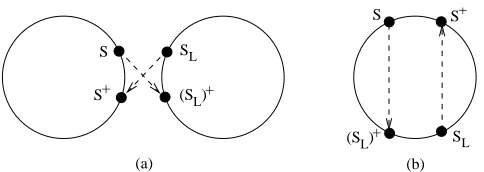
Fig. 2.Possible outcomes of exchangingS+ and(SL)+: (a) Two cycles join into one; (b) One
cycle split into two.
IfSand its left complement SL belong to different cycles then, as shown in Fig-ure 2a, by exchangingS+and(SL)+, we join these two cycles into one. Contrary, ifS andSL belong to the same cycle then, as shown in Figure 2b, by exchangingS+and (SL)+, we split this cycle into two.
Theorem 2. An(n,k)-composed register has
Ck= k−1
∑
i=0 2i∗n+1
cycles, in which one cycle is a zero cycle and other cycles are of length2n−1. Proof. By induction ofk.
Basic case:Obviously, for thek=1,C1=2. We have one zero cycle and one non-zero
cycle consisting of 2n−1 non-zero states.
Induction step:Suppose that the theorem holds fork. Consider(n,k+1)-composed
registerN0constructed fromk+1n-stage NLFSRsN1,N2, . . . ,Nk,Nk+1. The NLFSRs N1,N2, . . . ,Nk induce an(n,k)-composed registerN. By inductive hypothesis, N has one zero cycle andCk−1 other cycles of length 2n−1. In the proof, we refer to the latter cycles asnon-zerocycles onN.
We can partition the cycles ofN0into four types:
1. A cycle obtained by composing the zero cycle ofNwith the zero cycle ofNk+1. We get a single cycle of length one.
2. A cycle obtained by composing the zero cycle ofNwith the non-zero cycle ofNk+1. We get a single cycle of length 2n−1.
3. Cycles obtained by composing theCk−1 non-zero cycles ofNwith the zero cycle ofNk+1. We getCk−1 cycles of length 2n−1 each.
4. Cycles obtained by composing theCk−1 non-zero cycles ofNwith the non-zero cycle ofNk+1. We get(Ck−1)∗(2n−1)cycles of length 2n−1 each.
Thus, the total number of non-zero cycles inN0is 1+ (Ck−1)∗2n=∑ki=02i∗n= Ck+1−1.
5
Constructing Registers with Period
O
(
2
2n)
In this section, we show how to obtain cycles with periodO(22n)by adding to an(n,k )-composed register using a logic of sizeO(n∗k).
5.1 Cycle joining transformations
First, we analyze cycles obtained by exchanging the statesSminand(Smin)Lof all cycles of an(n,k)-composed register.
Theorem 3. If, for every cycle of an (n,k)-composed register, the successors of Smin
and (Smin)L are exchanged, then the resulting register has Ck−1−1 cycles of length (2n−1)∗2nand one cycle of length2n.
Proof. Consider(n,k+1)-composed registerN0constructed from the NLFSRsN1,N2, . . . ,Nk,Nk+1. NLFSRsN1,N2, . . . ,Nk induce an(n,k)-composed registerN which, by Theorem 2, has one zero cycle andCk−1 other cycles of length 2n−1.
We partition the cycles ofN0 into the same four types of cycles as in the proof of Theorem 2:
1. For the cycle of type 1, its minimal state is all-zero. The left complement of the minimal state consists ofkconcatenatedn-tuples(100. . .0).
2. For the cycle of type 2, its minimal state consists ofk−1 concatenated all-zeron -tuples followed by then-tuple(100. . .0). The left complement of the minimal state consists ofk−1 concatenatedn-tuples(100. . .0)followed by the all-zeron-tuple. 3. For each of the cycles of type 3, its minimal state is a concatenation of the minimal state of the corresponding cycle inNwith the all-zeron-tuple. The left complement of the minimal state is a concatenation of the of the left complement of the minimal state of the corresponding cycle inNand then-tuple(100. . .0).
4. For each of the cycles of type 4, its minimal state is a concatenation of some state of the corresponding cycle inNwith then-tuple(100. . .0). The left complement of the minimal state is a concatenation of the of the left complement of some state of the corresponding cycle inNand the all-zeron-tuple.
From the description above we can see that, for each cycle of type 4, the left com-plement of the minimal state of the cycle is either of type 3 or of type 1. It is of type 1 for the cycle whose minimal state consists ofkconcatenatedn-tuples(100. . .0). Since there are(Ck−1)∗(2n−1)cycles of type 4, we can conclude that(Ck−1)∗(2n−1)−1 states in the cycles of type 3 are left complement of some minimal state of some cycle of type 4. The remaining one state in the cycles of type 3 consists ofk−1 concate-natedn-tuples(100. . .0)followed by the all-zero state. It is the left complement of the minimal state of the cycle of type 2.
...
...
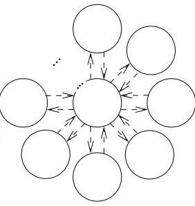
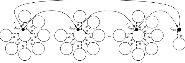
Fig. 3.The ”flower” cycle structure.
also get one cycle of length 2nwhich joins the all-zero state ofN0with the cycle ofN0 whose minimal state consists ofkconcatenatedn-tuples(100. . .0).
Finally, we show that the cycles we described contain all states ofN0. On one hand, from Figure 3 we can conclude that the overall number of states contained inCk−1 ”flower” cycles and the other cycles areA= (Ck−1)∗(2n−1)∗2n+2n. On the other hand, if we sum up the number of states in the cycles of types 1, 2, 3 and 4, we get 1+ (2n−1) + (Ck−1)∗(2n−1) + (Ck−1)∗(2n−1)∗(2n−1) =A.
2
The functions f(x1,x2, . . . ,xn)andf(x1,x2, . . . ,xn)⊕ s1 x1
s2 x2. . .
sn xn, where
si
xiis defined as:
si xi=
xi, if si=0 xi, if si=1
evaluate to the same values for all assignments of their variables except(s1,s2, . . . ,sn). This implies that we can change the next state of a state(s1,s2, . . . ,sn)of ann-stage NLFSR with the feedback function f(x1,x2, . . . ,xn)from (s2, . . . ,sn, f(s1,s2, . . . ,sn))
to(s2, . . . ,sn, f(s1,s2, . . . ,sn))by adding to fthe minterm s1 x1
s2 x2. . .
sn
xn. Consequently, an
(n,k)-composed register in which the statesS+minand((Smin)L)+are exchanged can be
obtained by adding to the feedback function of every NLFSRNi the minterms corre-sponding to the statesSminand(Smin)L.
5.2 Extra logic block
Theorem 4. The set of minimal states of all cycles of an (n,k)-composed register is represented by the following Boolean function:
fmin(x1,x2, . . . ,xn∗k) = k−1
_
i=0 (xi∗n+1·
n∗k
∏
j=i∗n+2 xj)∨
n∗k
∏
j=1
xj (1)
and the set of left complements of its minimal states is represented by:
fminL(x1,x2, . . . ,xn∗k) = Wk−i=01(∏nj=i∗n+1xj·∏k−i−p=11(xn∗(i+p)+1·∏mn−=1n∗(i+p)+2xm))∨
∨∏k−p=10(xn∗p+1·∏n−m=1n∗p+2xm).
(2) where ”∨” stands for the Boolean OR.
Proof. By induction ofk.
Basic case:k=1, i.e.N=N1. Then the equation (1) reduces to
fmin(x1,x2, . . . ,xn) = (x1· n
∏
j=2 xj)∨
n
∏
j=1 xj
which correspond to the minimal state(1,0, . . . ,0)of the cycle of length 2n−1 ofN1 and to the minimal state(0,0, . . . ,0)of the zero cycle ofN1.
The equation( 2) reduces to
fminL(x1,x2, . . . ,xn) = n
∏
j=1
xj∨(x1· n−1
∏
m=2 xm)
which correspond to the left complements of the minimal states of the cycle of length 2n−1 ofN
1and zero cycle ofN1, respectively.
Induction step:Suppose that the theorem holds fork. Consider(n,k+1)-composed
registerN0constructed fromk+1n-stage NLFSRsN1,N2, . . . ,Nk,Nk+1. The NLFSRs N1,N2, . . . ,Nkinduce an(n,k)-composed registerN. By inductive hypothesis, their set of minimal states is represented by the equation (1). The product-terms of the equa-tion (1) are listed in the following table withk+1 rows:
Smin Corresponding 1 2 3. . .k product-term
0 0 0. . . 0 x1x2. . .xn∗k
1 0 0. . . 0 x1x2. . .xn∗k
x 1 0. . . 0 xn+1xn+2. . .xn∗k
x x 1. . . 0 x2∗n+1x2∗n+2. . .xn∗k . . . .
x x x. . . 1 x(k−1)∗n+1x(k−1)∗n+2. . .xn∗k
In this table,0 denotes ann-tuple consisting of all zeros:0= (0,0, . . . ,0),1denotes ann-tuple consisting of 1 followed byn−1 zeros:1= (1,0, . . . ,0), andxdenotes an n-tuple consisting of all x:x= (x,x,. . .,x), where the symbol ”x” means either 0 or 1.
1. Cycles obtained by composing the zero cycle ofNk+1with all cycles ofN. 2. Cycles obtained by composing the non-zero cycle ofNk+1with all cycles ofN.
For each cycle in the first group, its minimal stateS0min is a concatenation of the minimal state Smin of the corresponding cycle ofN and the all-zeron-tuple, i.e. it is of type S0min= (Smin,0). Therefore, the Boolean function fmin1 representing the set of minimal states of all cycles in the first group is of type
fmin1 = k+1 _
i=1
pi·xk∗n+1xk∗n+2. . .xn∗(k+1)
wherepiis the product-term from theith row of the table above.
For each cycle in the second group, its minimal stateS0min is a concatenation of some stateS of the corresponding cycle ofN and the state ofNk+1 with the decimal representation 1, i.e. it is of typeS0min= (S,1). Since cycles an(n+1,k)-composed registerN0represent all possible combinations which can be obtained from the cycles of N1,N2, . . . ,Nn, the set of minimal states in the second group is composed of all possible states of (n,k)-composed register N and1. Therefore, the Boolean function fmin2 representing the set of minimal states of all cycles in the second group is of type
fmin2 =xk∗n+1xk∗n+2. . .xn∗(k+1).
By taking the Boolean OR of fmin1 and2min, we get equation (1) fork=k+1.
Since the left complement of ann-tuple0is1and vice-verse, for the left comple-ments of the minimal states of(n,k)-composed registerNwe get the following table:
(Smin)L Corresponding 1 2 3. . .k product-term
1 1 1. . . 1 x1x2. . .xnxn+1xn+2. . .x2∗n. . .x(k−1)∗n+1x(k−1)∗n+2. . .xn∗k
0 1 1. . . 1 x1x2. . .xnxn+1xn+2. . .x2∗n. . .x(k−1)∗n+1x(k−1)∗n+2. . .xn∗k
x 0 1. . . 1 xn+1xn+2. . .x2∗nx2∗n+1x2∗n+2. . .x3∗n. . .x(k−1)∗n+1x(k−1)∗n+2. . .xn∗k
x x 0. . . 1 x2∗n+1x2∗n+2. . .x3∗nx3∗n+1x3∗n+2. . .x4∗n. . .x(k−1)∗n+1x(k−1)∗n+2. . .xn∗k . . . .
x x x. . . 0 x(k−1)∗n+1x(k−1)∗n+2. . .xn∗k
For the cycles in the first group, the set of left complements of the minimal states
(n+1,k)-composed registerN0consists of states(Smin0 )L= ((Smin)L,1), for all left
com-plements of the minimal states(Smin)LofN. Therefore, the Boolean function fminL1 rep-resenting the set of left complements of the minimal states of all cycles in the first group is of type
fminL1 = k+1
_
i=1
pi·xk∗n+1xk∗n+2. . .xn∗(k+1)
wherepiis the product-term from theith row of the table above.
For the cycles in the second group, the set of left complements consists of states
... output
+ f2(x2 + +
,1,x2,2, . . . ,x2,n)
k,2 k,1
fk(xk,1,xk,2, . . . ,xk,n)
k,n 2,2
2,1 2,n
1,2 1,1
f1(x1,1,x1,2, . . . ,x1,n)
1,n
fmin(x1,1, . . . ,xk,n)
∨fminL(x1
,1, . . . ,xk,n)
f
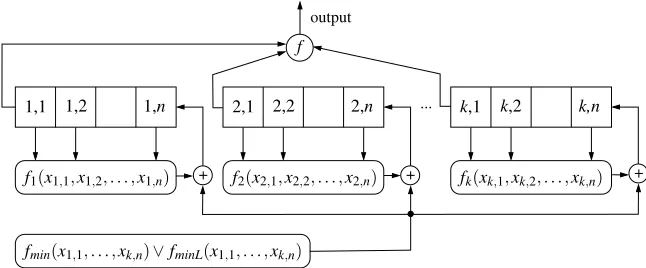
Fig. 4. General structure of a register with period (2n−1)∗2n constructed from an (n,
k)-composed register by exchanging the successors ofSminand (Smin)L of all cycles. The block
implementing fmin∨fminLis of sizeO(n∗k). To avoid overloading the picture, the arrows from
all stages(i,j), fori∈ {1,2, . . . ,n},j∈ {1,2, . . . ,k}, to this block are omitted.
ofN. Therefore, the Boolean function fminL2 representing the set of left complements of the minimal states of all cycles in the second group is of type
fmin2 =xk∗n+1xk∗n+2. . .xn∗(k+1).
By taking the Boolean OR of fminL1 andfminL2 , we get equation (2) fork=k+1.
2
Some optimizations can be done to reduce the size of the expression fmin∨fminL. First, the product-terms in the first two rows of both tables in the proof of Theorem 3 can be joined into product-terms x2. . .xn∗k andx2. . .xnxn+1xn+2. . .x2∗n. . .x(k−1)∗n+1 x(k−1)∗n+2. . .xn∗k. In the proof, we kept them separately in order to give a better view on the structure of fminandfminL. Also, the product-terms in the last rows of both tables can be joined into the product-termx(k−1)∗n+2. . .xn∗k. In this way, the overall number of product-terms in fmin∨fminLcan be reduced to 2∗k−1.
Furthermore, note that the product-terms of fmin∨fminL have common sub-terms x2. . .xn,xn+2. . .x2∗n,. . .,x(k−1)∗n+2. . .xn∗k. Each of these common sub-terms can to be represented only once and shared by all product-terms. In this way, the number of literalsx.iin the representation of fmin∨fminLcan be reduced toO(n∗k). So, the block
fmin∨fminLcan be implemented withO(n∗k)2-input gates2.
The general structure of a register with period(2n−1)∗2nconstructed using The-orem 3 is shown in Figure 4.
. .. . . .
.. . . . .
. .. .
.. . . .
... ...
Smin
Smin S
min
Smin
Fig. 5.Connecting all cycles into one.
6
Constructing Registers with the Maximum Period
In this section, we show how to join cycles of a register constructed using Theorem 3 into one cycle.
6.1 Cycle joining transformations
The approach described in the previous section allows as to constructn∗k-stage regis-ters which have∑k−i=022
i∗ncycles of length(2n−1)∗2nand one cycle of length 2n. The following Theorem shows how to join these cycles into one.
Theorem 5. Let N be an n∗k-stage register constructed using Theorem 3. If the
fol-lowing transformations are applied to each current state S of N before computing the next state:
T1: If D(S)∈ {2i∗n,2i∗n+1, . . . ,2i∗n+1−2}, for i={1,2, . . . ,k−2}, then S is trans-formed to the state S0such that D(S0) =D(S) +1,
T2: If D(S) =2i∗n+1−1for i={0,1, . . . ,k−3}, then S is transformed to the state S0 such that D(S0) =2(i+1)∗n,
T3: If D(S) =2(k−2)∗n+1−1, then S to is transformed to the state S0such that D(S0) =0, T4: If D(S) =0, then S is transformed to the state S0such that D(S0) =D(S) +1,
then the resulting register has period2n∗k.
Proof. Consider ann∗k-stage registerNconstructed using Theorem 3.Nhas∑k−i=022i∗n
cycles of length(2n−1)∗2nand one cycle of length 2n. The cycles of length(2n−1)∗ 2nhave the ”flower” structure shown in Figure 3.
We can connect all cycles ofNtogether by transforming the minimal state of the middle cycle of each ”flower” into the minimal state of the middle cycle of the next ”flower” before computing the next state ofN, and finally appending to the resulting chain of ”flowers” the cycle of length 2n, as shown in Figure 5.
Smin 1 2 3. . .k−1k
1 0 0. . . 0 0
x 1 0. . . 0 0
x x 1. . . 0 0
. . .
x x x. . . 1 0
The table above containsk−1 rows. For eachi∈ {0,1, . . . ,k−2}, the rowi repre-sents a block of 2i∗nminimal states of the middle cycle of a ”flower” with the decimal representations {2i∗n,2i∗n+1, . . . ,2i∗n+1−2}. We order the states in each block ac-cording to theirD(S). Then, fori={1,2, . . . ,k−2}, we can visit all states in a block by incrementing by 1D(S)of each stateSin the block but the last. This is done by the transformationT1. To visit all blocks, fori∈ {0,1, . . . ,k−3}, we go from the last state of the blocki, which hasD(S) =2i∗n+1−1, to the first state of the blocki+1, which hasD(S0) =2(i+1)∗n. This is done by the transformationT2.
In order to append the cycle of length 2nto the resulting chain of ”flowers”, we go from the last state of the last block, which hasD(S) =2(k−2)∗n+1−1, to the minimal state of the cycle of length 2n, which is the all-0 state. This is done by the transformation T3. Finally, we close the cycle by the going from the all-zero state to first state of the first block. This is done by incrementingD(S)of all-0 state by 1, i.e. by the transformation T4.
Thus, by applying the transformation’sT1, T2, T3andT4, we join all cycles ofN into one.
2
As an example, consider the simple case ofk=2 for which we only need to trans-form the state(1,0)into(0,0)and vice verse. This can be done using ann∗k−1 input NOR gate with inputs from all the stages but(1,1)and a 2-input XOR gate with inputs from the stage(1,1)and the NOR gate and the output to the stage(1,1). In this way, we complement the value of the stage(1,1)only if all the remaining stages have the value 0. Sincex2+x3+. . .+xn∗k=x2x3. . .xn∗kand the product-termx2x3. . .xn∗kis used for implementing the function fmin, it brings no extra cost.
In the next section, we show that, in the general case, the transformationsT1, T2, T3andT4requireO(n∗k2)2-input gates to be implemented.
The registers constructed using Theorem 5 require two time steps to compute the next step from a current step. At the first step, we update the current state by applying the transformationsT1, T2, T3andT4. At the second step, we compute the next state from the resulting updated state.
6.2 Extra logic block
In the general case ofk>2, we can implement the transformationsT1andT4using an (k−2)∗n-bit adder in which one of the operands is 0 or 1, supplied by a controlling OR described below, and another operand is the content of the stages of the firstk−
n-bit NLFSRs. The adder is controlled by an OR-gate with inputs from the product-terms implementing the set states withD(S)∈ {2i∗n,2i∗n+1, . . . ,2i∗n+1−2}, fori=
{1,2, . . . ,k−2}, and the all-zero state. The addition of 1 is performed only if one of the product-terms evaluates to 1. A(k−2)∗n-bit adder can be implemented withO(n∗k) 2-input gates. The controlling logic can also be implemented withO(n∗k)2-input gates. The transformationsT2andT3can be implemented by assigning to each stage(i,j), for everyi∈ {1,2, . . . ,n}andj∈ {1,2, . . . ,k−2}, and fori=1 and j=k−1, a 2-input XOR gate, with inputs from the stage(i,j)and a controlling OR gate described below and the output to the stage (i,j). The OR-gates take inputs from the product-terms implementing the set of states withD(S) =2i∗n+1−1 fori={0,1, . . . ,k−2}. Only if one of the product-terms evaluates to 1, the outputs of ORs fed by this product-term become 1. That results in complementing values of all stages controlled by these ORs. We needO(n∗k)controlling ORs and each OR can have up tok−1 inputs. Therefore, the controlling logic for the transformationsT2andT3requiresO(n∗k2)2-input gates. So, the overall complexity of implementing the transformationsT1, T2, T3andT4 isO(n∗k2)2-input gates. Note that many of the product-terms used for implementing T1, T2, T3andT4are also used for implementing fminandfminL, so they can be shared.
7
Conclusion
In this paper, we presented a method for constructingn∗k-stage registers with period 2n∗kby a composition ofk n-stage NLFSRs. First, we show that ann∗k-stage register with periodO(22n)can be constructed fromk n-stage NLFSRs by adding to their feed-back functions a logic block of sizeO(n∗k). Second, we show how to join all cycles into one by using one more logic block of sizeO(n∗k2)and an extra time step.
The presented method is feasible for generating very large full cycles. However, these cycles have a well-defined structure implied by the composition. This structure might be exploited by cryptanalysts for breaking sequences generated by n∗k-stage registers.
References
1. S. Golomb,Shift Register Sequences. Aegean Park Press, 1982.
2. K. Zeng, C. Yang, D. Wei, and T. R. N. Rao, “Pseudo-random bit generators in stream-cipher cryptography,”Computer, 1991.
3. R. David,Random Testing of Digital Circuits. New York: Marcel Dekker, 1998.
4. J. L. Massey, “Shift-register synthesis and BCH decoding,”IEEE Transactions on Informa-tion Theory, vol. 15, pp. 122–127, 1969.
5. E. Dubrova, M. Teslenko, and H. Tenhunen, “On analysis and synthesis of(n,k)-non-linear feedback shift registers,” inDesign and Test in Europe, pp. 133–137, 2008.
6. E. Dubrova, “A list of maximum-period NLFSRs.” Cryptology ePrint Archive, Report 2012/166, 2012. http://eprint.iacr.org/2012/166.
7. B. Schneier,Applied cryptography (2nd ed.): protocols, algorithms, and source code in C. New York, NY, USA: John Wiley & Sons, Inc., 1995.
9. H. Fredricksen, “A survey of full length nonlinear shift register cycle algorithms,”SIAM Review, vol. 24, no. 2, pp. 195–221, 1982.
10. H. Fredricksen, “A class of nonlinear deBruijn cycles,”J. Comb. Theory, vol. 19, pp. 192– 199, Sept. 1975.
11. T. Etzion and A. Lempel, “Algorithms for the generation of full-length shift register se-quences,”IEEE Transactions on Information Theory, vol. 3, pp. 480–484, May 1984. 12. C. J. A. Jansen,Investigations On Nonlinear Streamcipher Systems: Construction and
Eval-uation Methods. Ph.D. Thesis, Technical University of Delft, 1989.
13. F. S. Annexstein, “Generating de Bruijn sequences: An efficient implementation,” IEEE Transactions on Computers, vol. 46, pp. 198 – 200, 1997.
14. T. Chang, B. Park, Y. H. Kim, and I. Song, “An efficient implementation of the D-homomorphism for generation of de Bruijn sequences,”IEEE Transactions on Information Theory, vol. 45, pp. 1280–1283, 1999.
15. H. M. Fredricksen, “Disjoint cycles from de Bruijn graph,” Tech. Rep. 225, USCEE, 1968. 16. E. Dubrova, “A scalable method for constructing Galois NLFSRs with period
2n−1 using cross-join pairs.” Cryptology ePrint Archive, Report 2011/632, 2011. http://eprint.iacr.org/2011/632.
17. T. Helleseth and T. Kløve, “The number of cross-join pairs in maximum length linear se-quences,”IEEE Transactions on Information Theory, vol. 31, pp. 1731–1733, 1991. 18. R. K. Brayton, C. McMullen, G. Hatchel, and A. Sangiovanni-Vincentelli,Logic
Minimiza-tion Algorithms For VLSI Synthesis. Kluwer Academic Publishers, 1984.
19. T. W. Cusick and P. Stˇanicˇa,Cryptographic Boolean functions and applications. San Diego, CA, USA: Academic Press, 2009.
20. E. Dubrova and M. Teslenko, “Compositional properties of random Boolean networks,” Physical Review E, vol. 71, p. 056116, May 2005.
21. B. Gammel, R. G¨ottfert, and O. Kniffler, “Achterbahn-128/80: Design and analysis,” in SASC’2007: Workshop Record of The State of the Art of Stream Ciphers, pp. 152–165, 2007. 22. B. Gittins, H. A. Landman, S. O’Neil, and R. Kelson, “A presentation on VEST hardware performance, chip area measurements, power consumption estimates and benchmarking in relation to the aes, sha-256 and sha-512.” Cryptology ePrint Archive, Report 2005/415, 2005. http://eprint.iacr.org/.