Implementation Of Adaptive Filter In Dstatcom
S.Anusharani
(PG Scholor, Dept of EEE ,SKD, Gooty, Andhrapradesh, India.)
N.Narasimhulu
(Associate Professor & HOD, Dept of EEE, SKD, Gooty, Andhrapradesh,
India)
Dr.R.Ramachandra
(Principal SKD, Gooty, Andhrapradesh, India)
Abstract:-Non sinusoidal current in a distribution system is mainly due to nonlinear characteristics of equipment such as adjustable speed drives, switch-mode power supplies, rectifiers, and others such type of loads. In most cases, nonlinear loads are represented either as a harmonic current source or a harmonic voltage source in practical applications and responsible for
creating power-quality problems. Mitigation of
power-quality problems can be achieved by using passive or active filters; however, due to certain advantages of active filter (AF) with digital control, it is used for improving power quality. An improved version of a shunt-connected AF used in the distribution system is known as a distribution static compensator (DSTATCOM). It is used for compensation of current-related power-quality problems such as reactive-power compensation, harmonics elimination, and load balancing in power factor correction (PFC) mode and zero voltage regulation (ZVR) mode. Improved responses and capacity for transient overload even at a reduced voltage level are the major advantages of DSTATCOM. Various international standards such as IEEE and IEC have reported the guidelines of harmonics limit at the point of common coupling (PCC).
Effective utilization of a converter used as a DSTATCOM depends upon the control algorithm used for extraction of reference currents and switching schemes. For extracting reference signals, many time-domain control algorithms are available, which are based on phase-dictated sinusoid-tracking parameter extraction of non stationary sinusoidal, amplitude phase-locked loop (PLL), etc; unit template-based control algorithm without sensing load currents;
one-cycle control, which has excellent harmonics
suppression, simple circuitry, robust performance, and low cost linear feedback control and signal-processing algorithm for selective harmonic identification based
on heterodyning, moving-average finite-impulse
response filters, and PLL using feed forward based control. These algorithms are based on basic arithmetic
operation of mathematical function, transform, tuning of internal constants, clock, an integrator, flip-flops, comparators and logic circuits, etc. The performance of these classical control algorithms depends upon selection and tuning of internal parameters, circuit components, and their formulations.
an AF is implemented in three-phase distorted voltage ac mains for reactive-power compensation, harmonics elimination, and load balancing with a self-supporting dc link in PFC and ZVR modes of DSTATCOM. This proposed control algorithm is also modified for DSTATCOM operation in ZVR mode. The main features of this control approach are high convergence speed and robustness with respect to input frequency and internal parameter variations and less sensitivity to voltage pollutions when it is used as a reactive-power component of current extraction. Design of control algorithm only needs multiplications, integral, gain, and subtraction blocks. Thus, the structure of this control algorithm is based on basic arithmetic operation; hence, its implementation is simple, and it does not require any extra synchronization circuit. Selected values of integral constants are not affecting the performance of the filter within a certain range. The simulations were performed in the environment of MATLAB/SIMULINK.
INTRODUCTION
Voltage source converters (VSC’s)
improper operation of other EMI sensitive loads/equipment on the grid.
One method to prevent pollution of the utility by high frequency current ripple is to use an
RLC filter at the input of the VSC. The RC
elements in the filter provide a low impedance path for the high-frequency components, preventing them from entering the utility. A resistor in series with a capacitor is used for damping the high-frequency resonance in the filter. Because of the power losses in the resistor, and its additional cost,
it is advantageous to use only an LC input filter and
make use of control algorithms to “actively” damp resonance. Two principally different approaches are used in [1]–[3] to damp resonance in the output
LC(R) filter of an inverter. The method in [3] is
based on an additional current feedback in the LC
filter and introduces extra cost of the current sensor. In [1] and [2], the voltage from the capacitor is used for active damping in the stationary and synchronous reference frames, respectively.
LITERATURE SURVEY
Non sinusoidal current in a distribution system is
mainly due to nonlinear characteristics of equipment such as adjustable speed drives, switch-mode power supplies, rectifiers, and others such type of loads [1]. In most cases, nonlinear loads are represented either as a harmonic current source or a harmonic voltage source in practical applications
and responsible for creating power-quality
problems [2]. Mitigation of power-quality
problems can be achieved by using passive or active filters; however, due to certain advantages of active filter (AF) with digital control, it is used for improving power quality [3], [4]. An improved version of a shunt-connected AF used in the distribution system is known as a distribution static compensator (DSTATCOM) [5], [6]. It is used for compensation of current-related power-quality problems such as reactive-power compensation, harmonics elimination, and load balancing in power factor correction (PFC) mode and zero voltage regulation (ZVR) mode [7], [8]. Improved responses and capacity for transient overload even at a reduced voltage level are the major advantages of DSTATCOM. Various international standards such as IEEE and IEC have reported the guidelines of harmonics limit at the point of common coupling (PCC) [9], [10].
Effective utilization of a converter used as a DSTATCOM depends upon the control algorithm used for extraction of reference currents and switching schemes [11]–[13]. For extracting reference signals, many time-domain control algorithms are available, which are based on phase-dictated sinusoid-tracking parameter extraction of non stationary sinusoidal, amplitude phase-locked loop (PLL), etc. [14]–[17]; unit template-based control algorithm without sensing load currents [18]; one-cycle control, which has excellent harmonics suppression, simple circuitry, robust performance, and low cost [19]; linear feedback control [20]; and signal-processing algorithm for
selective harmonic identification based on
heterodyning, moving-average finite-impulse
response filters, and PLL using feed forward based control [21]. These algorithms are based on basic arithmetic operation of mathematical function, transform, tuning of internal constants, clock, an integrator, flip-flops, comparators and logic circuits, etc. The performance of these classical control algorithms depends upon selection and tuning of internal parameters, circuit components, and their formulations.
The field of adaptive system has been developed in terms of filter, design techniques, and analytical tools. It is the controller that can adjust its behavior in terms of response to changes in the dynamic of the disturbances. Based on this, many control algorithms are also reported in the available literature, such as the adaptive nature of the Adaline [22], [23], artificial immune system-based adaptive control where parameter estimation is based on particle swarm optimization [24], robust adaptive control implemented using an adaptive pole-placement control technique [25], improved adaptive detection algorithm for selective harmonic detection where convergence of extracted signal depends on selected value of gains [26], and an adaptive digital filter with a synchronized filtered-X (SFfiltered-X) algorithm.
The SFX-ADF-based algorithm for a current controller exhibits high gains only at fundamental and harmonic frequencies of the load current. It automatically adjusts its transfer function to minimize the mean square error. Moreover, only a proportional controller is used to improve the dynamic performance of the current control system [27]. Other adaptive control algorithms used in
algorithms [28], [29], least-mean-square-based control algorithms applied to adjust the coefficients of the adaptive notch filter where Clarke transformation with a low-pass filter (LPF) is used to detect the load current amplitude [30], and model reference adaptive control where its advantages over conventional proportional–integral (PI) control are flexibility, adaptive, and robustness [31]. In these control algorithms, performances are based on a fixed learning rate, transform-based
conversion, and tuning of many internal
parameters.
ESTIMATION OF SIN AND COS COMPONENT OF PCC VOLTAGES
The sinusoidal-tracking algorithm is used
for extraction of phase “a” sin θva and cos θva
component of distorted PCC voltages as unit templates in adaptive nature [14].
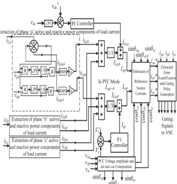
Fig..1: Generation of reference supply currents using Adaptive Filter
The block diagram of this algorithm is shown in Fig.2. Error in the phase “a” voltage is the
difference between vsaand vso, and it is denoted by
Ve. A1, A2, and A3 are internal constants of the
algorithm, which are positive-real values. The selection process of internal constants is described in [15]–[17], and these constants decide the behavior of the algorithm in terms of convergence speed and accuracy. The values of these internal
parameters A1, A2, and A3 are considered as 4, 2,
and 1.5 for this implementation. The proposed
algorithm is able to indentify sinusoidal
components of input that is close to fundamental frequency after assigning an initial condition in its integration block. It is observed that the variations
in sin θva and cos θva components of the phase “a”
PCC phase voltage are effectively tracked in less than a couple of cycles. The number of tracking cycles is reduced by increasing the value of internal constants up to a certain extent. The advantages of this algorithm are low computational time, robustness with respect to frequency variation, and high estimation accuracy, which are necessary in most practical applications. Similarly, sin θ and cos θ components (sin θvb, cos θvb and sin θvc, cos θvc) of phase b and c are also estimated.
Fig. 2: Estimation of phase voltage vpaand
vqacomponents
ESTIMATION OF AMPLITUDE OF ACTIVE- AND REACTIVE-POWER COMPONENTS OF LOAD CURRENTS
Active-power, reactive-power, and
harmonics components of load currents are the primary components in distorted and lagging power factor load currents. Active- and reactive-power components of phase “a” load current are subtracted from the original load current, and the generated error is multiplied with the in-phase
component of PCC voltage (vpa). This signal is
passed through an LPF before integration. After integration with a proper constant, this component is again multiplied with the in-phase component of
PCC voltage (vpa) in a closed loop system. The
active-power component of phase “a” load current
(iLpa1) is extracted from the original load current
using the previously described procedure in adaptive nature. After extraction of the active-power component of load current, its root-mean-square value is estimated and converted to a peak value using gain (G). The amplitude of the estimated active power component of phase “a”
load current is iLpa. Similarly, the amplitude of the
active component of phase “b” and phase “c” load
currents iLpband iLpcare estimated.
For extraction of the reactive-power component of load current, an error signal is multiplied with the quadrature component of PCC
voltage (vqa). After integration of this component
reactive-power component of phase “a” load current (iLqa1). After extraction of the reactive-power component of load current, its root-mean square value is estimated and converted to a peak value using gain (G). The amplitude of the reactive-power
component of phase “a” load current is “iLqa.”
Similarly, the amplitude of the reactive-power component of phase “b” and phase “c” load
currents iLqband iLqcare estimated. The amplitudes of
average fundamental active- and reactive-power components of load currents of three-phase loads are estimated using the amplitude sum of individual three-phase active- and reactive-power components of loads divided by 3.
SIMULATION RESULT ANALYSIS
Performance of AF
Fig. 3 shows the various intermediate signals of the control algorithm, which include
phase “a” distorted-voltage waveform (vsa),
filtered-voltage waveform (vsa1), load current (iLa).
The scale of phase “a” voltage “vsa” and vsa1 is 200
V/div, and other signals’ scale is 20 A/div with time in the x-axis. Extraction of these control signals under load injection is shown in Fig. 5.2 respectively, which demonstrates the variation and extraction speed of control signals using the proposed AF under time-varying non linear load in ZVR mode of DSTATCOM.
Fig.3: Various intermediate signals of the control algorithm at load injection
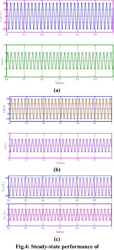
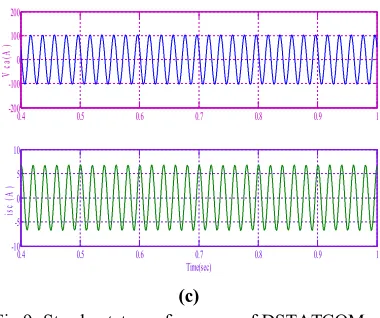
Steady-State Performance of
DSTATCOM at Linear and Nonlinear Loads in PFC Mode:
Three PCC voltages (vab, vbc, vca) and
respective supply currents (isa, isb, isc) are shown in
Fig. 5.3(a)–(c). It is observed that PCC voltage drops from rated value due to supply impedance and load demand.
(a)
(b)
(c)
Fig.4: Steady-state performance of DSTATCOM at linear lagging PF load in
PFC mode
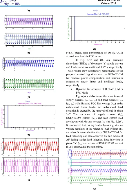
Fig. 4 (a)–(f) shows the waveform of
three-phase PCC voltages (vab, vbc, vca) with
respective phase supply currents (isa, isb, isc),
harmonic spectrum of phase “a” supply current and
distorted waveform of phase “a” load current (iLa)
and its harmonic spectrum under three diode-based rectifier loads.
0.2 0.3 0.4 0.5 0.6 0.7 0.8 0.9 1
-200 0 200
V
o
lt
a
g
e
(
V
sa
)
0.2 0.3 0.4 0.5 0.6 0.7 0.8 0.9 1
-200 0 200
V
o
lt
a
g
e
(
V
sa
1
)
0.2 0.3 0.4 0.5 0.6 0.7 0.8 0.9 1
-20 0 20
C
u
rr
e
n
t
(I
L
a
)
0.2 0.3 0.4 0.5 0.6 0.7 0.8 0.9 1
-20 0 20
Time(sec)
IL
P
A
0.4 0.5 0.6 0.7 0.8 0.9 1
-100 -50 0 50 100
V
ab
(
V
)
0.4 0.5 0.6 0.7 0.8 0.9 1
-10 -5 0 5 10
Time(sec)
is
a
(A
)
0.4 0.5 0.6 0.7 0.8 0.9 1
-100 -50 0 50 100
V
b
c
(V
)
0.4 0.5 0.6 0.7 0.8 0.9 1 -10
-5 0 5 10
Time(sec)
is
b
(A
)
0.4 0.5 0.6 0.7 0.8 0.9 1 -100
0 100
V
c
a(
V
)
0.4 0.5 0.6 0.7 0.8 0.9 1
-10 -5 0 5 10
Time(sec)
is
c
(A
)
0.5 0.6 0.7 0.8 0.9 1
-200 -100 0 100 200
V
o
lt
ag
e
(V
)
0.5 0.6 0.7 0.8 0.9 1
-10 -5 0 5 10
Time(sec)
C
u
rr
en
t
(A
(a)
(b)
(c)
(d)
(e)
(f)
Fig.5.: Steady-state performance of DSTATCOM at nonlinear loads in PFC mode.
In Fig. 5.(d) and (f), total harmonic distortions (THDs) of the phase “a” supply current and load current are 4.4% and 3.65%, respectively. These results show satisfactory performance of the proposed control algorithm used in DSTATCOM for reactive power compensation and harmonics suppression under linear and nonlinear loads, respectively.
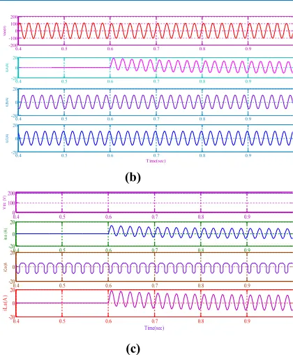
Dynamic Performance of DSTATCOM in
PFC Mode
Fig. 6(a) and (b) shows the waveforms of
supply currents (isa, isb, isc) and load currents (iLa,
iLb, iLc) with distorted PCC line voltage (vab) under
unbalanced linear loads. An unbalanced load condition is created by the removal of load in phase
“a.” The variation of supply current (isa),
DSTATCOM current (iCa), and load current (iLa)
are shown with dc-link voltage (vdc) in Fig. 5.5(c).
It is observed that during load unbalancing, dc-link voltage regulated at the reference level without any variation. It shows the function of DSTATCOM for load balancing and also observed the fast action of AF during sudden load injection. Load injection in
phase “a” (iLa) and action of DSTATCOM current
(iCa) is observed at the same time.
(a)
0.5 0.6 0.7 0.8 0.9 1
-200 -100 0 100 200
V
o
lt
ag
e
(V
)
0.5 0.6 0.7 0.8 0.9 1
-10 -5 0 5 10
Time(sec)
C
u
rr
en
t
(A
)
0.5 0.6 0.7 0.8 0.9 1
-200 -100 0 100 200
V
o
lt
ag
e
(V
)
0.5 0.6 0.7 0.8 0.9 1
-10 -5 0 5 10
Time(sec)
C
u
rr
en
t
(A
)
0 1 5 9 13 17 21 25 29 33 37 41 45 49
0 20 40 60 80 100
Harmonic order Fundamental (50Hz) = 8.3 , THD= 4.40%
M
ag
(
%
o
f
F
u
n
d
am
en
ta
l)
0.5 0.55 0.6 0.65 0.7 0.75 0.8 0.85 0.9 0.95 1
-200 -100 0 100 200
V
o
lt
ag
e
(V
)
0.5 0.55 0.6 0.65 0.7 0.75 0.8 0.85 0.9 0.95 1
-10 -5 0 5 10
C
u
rr
en
t(
A
)
0 1 5 7 9 13 17 21 25 29 33 37 41 45 49
0 50 100
Harmonic order Fundamental (50Hz) = 7.499 , THD= 3.65%
M
ag
(
%
o
f
F
u
n
d
am
en
ta
l)
0.4 0.5 0.6 0.7 0.8 0.9 1
-200 0 200
V
o
lt
ag
e
(V
)
0.4 0.5 0.6 0.7 0.8 0.9 1
-20 0 20
is
a
(
A
)
0.4 0.5 0.6 0.7 0.8 0.9 1
-20 0 20
is
b
(
A
)
0.4 0.5 0.6 0.7 0.8 0.9 1
-20 0 20
Time(sec)
is
c
(
A
(b)
(c)
Fig. 7: Dynamic performance of DSTATCOM at unbalanced linear loads
Fig. 8a) and (b) shows the waveforms of
supply currents (isa, isb, isc) and load currents (iLa,
iLb, iLc) in a dynamic condition with PCC line
voltage (vab) under nonlinear load. Fig.5.6(c) shows
the waveform of supply current (isa), DSTATCOM
current (iCa), and load current (iLa) with dc-link
voltage (vdc) under unbalanced load. These
results demonstrate satisfactory performance of AF under dynamic conditions. Fast action of this filter
is observed through DSTATCOM current (iCa) at
the time of load variation. Just at the time of load injection, the nature of DSTATCOM current is quickly changed, which validates the fast action of this AF.
(a)
(b)
(c)
Fig.8: Dynamic performance of DSTATCOM at unbalanced nonlinear loads
Steady-State Performance of
DSTATCOM Under Linear and Nonlinear Loads in ZVR Mode
Three-phase regulated PCC voltages (vab,
vbc, vca) are shown in Fig. 5.7(a)–(c). It is observed
that PCC voltage is regulated to near rated value.
(a)
0.4 0.5 0.6 0.7 0.8 0.9
-200 -100 0 100 200 V a b (V )
0.4 0.5 0.6 0.7 0.8 0.9
-20 0 20 iL A (A )
0.4 0.5 0.6 0.7 0.8 0.9
-20 0 20 iL B (A )
0.4 0.5 0.6 0.7 0.8 0.9
-20 0 20 Time(sec) iL C (A )
0.4 0.5 0.6 0.7 0.8 0.9 1
0 100 200 V d c ( V )
0.4 0.5 0.6 0.7 0.8 0.9 1
-20 0 20 is a ( A )
0.4 0.5 0.6 0.7 0.8 0.9 1
-20 0 20 iC a (A
0.4 0.5 0.6 0.7 0.8 0.9 1
-20 0 20 Time(sec) iL a( A )
0.4 0.45 0.5 0.55 0.6 0.65 0.7 0.75 0.8
-200 -100 0 100 200 V ab
0.4 0.45 0.5 0.55 0.6 0.65 0.7 0.75 0.8
-20 -100 10 20 is a
0.4 0.45 0.5 0.55 0.6 0.65 0.7 0.75 0.8
-20 -10 0 10 20 is b
0.4 0.45 0.5 0.55 0.6 0.65 0.7 0.75 0.8
-20 -10 0 10 20 Time(sec) is c
0.4 0.45 0.5 0.55 0.6 0.65 0.7 0.75 0.8
-200 0 200 V a b (V )
0.4 0.45 0.5 0.55 0.6 0.65 0.7 0.75 0.8
-10 0 10 iL a( A )
0.4 0.45 0.5 0.55 0.6 0.65 0.7 0.75 0.8
-10 0 10 iL b (A )
0.4 0.45 0.5 0.55 0.6 0.65 0.7 0.75 0.8
-10 0 10 Time(sec) iL c( A )
0.4 0.45 0.5 0.55 0.6 0.65 0.7 0.75 0.8
0 100 200 V d c (V )
0.4 0.45 0.5 0.55 0.6 0.65 0.7 0.75 0.8
-20 0 20 is a (A )
0.4 0.45 0.5 0.55 0.6 0.65 0.7 0.75 0.8
-10 0 10 iC a (A )
0.4 0.45 0.5 0.55 0.6 0.65 0.7 0.75 0.8
-10 0 10 Time(sec) iL a(A )
0.4 0.5 0.6 0.7 0.8 0.9 1
-200 -100 0 100 200 V ab (V )
0.4 0.5 0.6 0.7 0.8 0.9 1
-10 -5 0 5 10 Time(sec) is a (A )
0.4 0.5 0.6 0.7 0.8 0.9 1
-200 -100 0 100 200 V b c( V
0 0.1 0.2 0.3 0.4 0.5 0.6 0.7 0.8 0.9 1
(b)
(c)
Fig.9: Steady-state performance of DSTATCOM at linear lagging PF load in
ZVR mode
Fig. 10(a)–(e) shows the waveforms of
PCC line voltages (vab, vbc, vca) with supply currents
(isa, isb, isc) harmonic spectra of phase “a” supply
current and load current under nonlinear load. In Fig. 5.8(d) and (e), THDs of supply and load currents are 4.6% and 19.51%, respectively. The
waveform of DSTATCOM current (iCa) is shown in
Fig. 5.8(f).
(a)
(b)
(c)
(d)
(e)
0.4 0.5 0.6 0.7 0.8 0.9 1
-200 -100 0 100 200
V
ca
(A
)
0.4 0.5 0.6 0.7 0.8 0.9 1
-10 -5 0 5 10
Time(sec)
is
c
(A
)
0.4 0.5 0.6 0.7 0.8 0.9 1
-200 -100 0 100 200
V
o
lt
ag
e
(V
)
0.4 0.5 0.6 0.7 0.8 0.9 1
-20 -10 0 10 20
Time(sec)
C
u
rr
en
t
(A
)
0.4 0.5 0.6 0.7 0.8 0.9 1
-200 -100 0 100 200
V
o
lt
a
g
e
(
V
)
0.4 0.5 0.6 0.7 0.8 0.9 1
-20 -10 0 10 20
Time(sec)
C
u
rr
en
t
(A
)
0.4 0.5 0.6 0.7 0.8 0.9 1
-200 -100 0 100 200
V
o
lt
ag
e
(V
)
0.4 0.5 0.6 0.7 0.8 0.9 1
-20 0 20
Time(sec)
C
u
rr
en
t
(A
)
0 1 5 9 13 17 21 25 29 33 37 41 45 49
0 20 40 60 80 100
Harmonic order Fundamental (50Hz) = 11.3 , THD= 4.60%
M
ag
(
%
o
f
F
u
n
d
am
en
ta
l)
0 5 10 15 20 25 30 35 40 45 50
0 20 40 60 80 100
Harmonic order Fundamental (50Hz) = 8.847 , THD= 19.51%
M
ag
(
%
o
f
F
u
n
d
am
en
ta
(f)
Fig.10: Steady-state performance of DSTATCOM at nonlinear load in ZVR mode
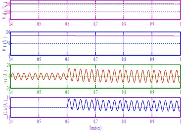
Dynamic Performance of DSTATCOM in
ZVR Mode
Fig. 11 shows the variation of dc-link
voltage, amplitude of PCC voltage (vt), phase “a”
supply current (isa), and load current (iLa) under an
unbalanced linear load condition. It demonstrates the fast action of AF during load injection.
Fig.11: Variation of Vt, isa, and iLa with vdc under
unbalanced linear loads
Fig. 12(a) and (b) shows the waveforms of
supply currents (isa, isb, isc) and load currents (iLa,
iLb, iLc) in a dynamic condition with PCC voltage
(vab) under nonlinear load. The variation of dc-link
voltage (vdc), amplitude of terminal voltage (Vt),
supply current (isa), and load current (iLa) are shown
in Fig. 5.10(c). These results demonstrate satisfactory performance of the proposed AF in a dynamic condition for the ZVR mode. In all cases, internal constants of this filter are the same, which shows the robustness in the application power quality.
(a)
(b)
(c)
Fig.12: Steady-state performance of DSTATCOM at nonlinear load in ZVR mode
CONCLUSION & FUTURE SCOPE CONCLUSION
A DSTATCOM has been implemented for a three-phase distribution system. An AF has been used for control of DSTATCOM. This AF has been found simple and easy to implement, and its performance has been observed satisfactory with non sinusoidal and distorted voltages of ac mains under load variation. The performance of DSTATCOM with its AF has been demonstrated
for harmonics elimination, reactive power
compensation, and load balancing with self-supporting dc link in PFC and ZVR modes. The dc-link voltage of the DSTATCOM has been also regulated to a desired value under time-varying load conditions.
FUTURESCOPE
0.4 0.5 0.6 0.7 0.8 0.9
-200 -100 0 100 200
V
o
lt
ag
e
(V
)
0.4 0.5 0.6 0.7 0.8 0.9
-10 -5 0 10
Time(sec)
iC
A
(
A
)
0.4 0.5 0.6 0.7 0.8 0.9 1
0 100 200
V
d
c(
V
)
0.4 0.5 0.6 0.7 0.8 0.9 1
0 50 100
V
t
(V
)
0.4 0.5 0.6 0.7 0.8 0.9 1
-20 0 20
is
a(
A
)
0.4 0.5 0.6 0.7 0.8 0.9 1
-10 0 10
Time(sec)
iL
a(
A
)
0.4 0.5 0.6 0.7 0.8 0.9 1
-200 -1000 100 200
V
ab
(V
)
0.4 0.5 0.6 0.7 0.8 0.9 1
-20 0 20
is
a(
A
)
0.4 0.5 0.6 0.7 0.8 0.9 1
-20 0 20
is
b
(
A
)
0.4 0.5 0.6 0.7 0.8 0.9 1
-20 0 20
Time(sec)
is
c
(A
)
0.4 0.5 0.6 0.7 0.8 0.9 1
-200 -100 0 100 200
V
ab
(
V
)
0.4 0.5 0.6 0.7 0.8 0.9 1
-20 0 20
iL
a
(A
)
0.4 0.5 0.6 0.7 0.8 0.9 1
-20 0 20
iL
b
(A
)
0.4 0.5 0.6 0.7 0.8 0.9 1
-20 0 20
Time(sec)
iL
c
(A
)
0.4 0.5 0.6 0.7 0.8 0.9 1
0 100 200
V
d
c
(V
)
0.4 0.5 0.6 0.7 0.8 0.9 1
0 100 200
V
t(
V
)
0.4 0.5 0.6 0.7 0.8 0.9 1
-20 0 20
is
a(
A
)
0.4 0.5 0.6 0.7 0.8 0.9 1
-20 0 20
Time(sec)
iL
a(
A
In future work, it will be report that the application of control
algorithm for
DSTATCOM in
multilevel converters.
REFERENCES
[1]. E. F. Fuchs
and M. A. S.
Mausoum, Power
Quality in Power Systems and Electrical Machines. London, U.K.: Elsevier, 2008.
[2]. H. Akagi, E. H. Watanabe, and M. Aredes,
Instantaneous Power Theory and Applications to Power Conditioning.
Hoboken, NJ, USA:
Wiley, 2007.
[3]. A. Emadi, A.
Nasiri, and S. B.
Bekiarov,
Uninterruptible Power Supplies and Active Filters. Boca Raton, FL, USA: CRC Press, 2005.
[4]. J. Jacobs, D. Detjen, C. U. Karipidis, and R.
W. De Doncker, “Rapid prototyping tools for power electronic systems: Demonstration with
shunt active power filters,” IEEE Trans. Power
Electron., vol. 19, no. 2, pp. 500–507, Mar. 2004.
[5]. A. Ghosh and G. Ledwich, Power Quality
Enhancement Using Custom Power Devices. New Delhi, India: Springer Int. Edition, 2009.
[6]. K. R. Padiyar, FACTS Controllers in Power
Transmission and Distribution. New Delhi, India: New Age Int., 2008.
[7]. S. B. Karanki, N. Geddada, M. K. Mishra, and
B. K. Kumar, “A DSTATCOM topology with reduced DC-link voltage rating for load
compensation with non-stiff source,” IEEE
Trans. Power Electron., vol. 27, no. 3, pp. 1201–1211, Mar. 2012.
[8]. B. Singh, P. Jayaprakash, and D. P. Kothari,
“A T-connected transformer and three-leg VSC based DSTATCOM for power quality
improvement,” IEEE Trans. Power Electron.,
vol. 23, no. 6, pp. 2710–2718, Nov. 2008. [9]. IEEE Recommended Practices and
Requirement for Harmonic Control on Electric Power System, IEEE Std.519, 1992.
AUTHORS:
1. S.ANUSHARANI was born in 1993. She completed her professional career of education in B.Tech (EEE) at Sri Krishnadevaraya engineering college in the year of 2014 and pursuing M.Tech from Sri Krishnadevaraya engineering college, Gooty, Anantapur(AP). She is
interested in Electrical Power Engineering.
2.Mr. N. Narasimhulu has completed his professional career of education in B.Tech (EEE) from JNTU Hyderabad. He obtained M.Tech degree from JNTU, HYDERABAD.Now he is pursuing Ph.d from JNTU ANANTAPUR. At present working as an Associate Professor and
Head of the EEE Department in Srikrishna
Devaraya Engineering College, Gooty of Anantapuramu district (AP).
3.Dr.R.RAMACHANDRA has completed his professional career of education in B.Tech (MECHANICAL) from JNTU Hyderabad. He
obtained M.Tech degree from JNTU,
Hyderabad.He obtained Phd degree from JNTU, Hyderabad At present working as Principal in