NexPath Telephony Server
System Administration Guide
For Software Release 5.
NTS SERVER HARDWARE LIMITED WARRANTY
THIS IS TO CERTIFY that the NexPath NTS Server hardware ("NTS Server") is hereby warranted to be free of all
defects in material and workmanship for one (1) year from the date of initial purchase from NexPath. This Warranty
does not apply to a defect caused by negligence, misuse, accidents, acts of God, or to any use not in accordance with
the instructions and specifications published by NexPath Corporation ("NexPath"). Use of the NTS Server in
emer-gency or time-critical or medical applications is not appropriate.
During the period of this Warranty, NexPath will repair or replace at our service center located in Santa Clara,
Cali-fornia, any part proving defective in material or workmanship. All expenses related to replacing or repairing a
defec-tive part under this Warranty will be assumed by NexPath except for the cost of transporting the product to NexPath's
service center, which shall be the responsibility of the buyer.
The buyer must notify NexPath of any defect, malfunction or nonconformity promptly upon discovery. Within 30 days
after receiving the NTS Server from the buyer, NexPath will repair or replace the defective part, at its own option,
provided that NexPath has found the NTS Server to be defective. CUSTOMER'S SOLE AND EXCLUSIVE
REME-DY HEREUNDER SHALL BE LIMITED TO THE REPAIR OR REPLACEMENT SPECIFIED HEREIN.
The foregoing warranties are contingent upon (1) the proper use of the hardware in accordance with the instructions
and specifications published by NexPath, (2) the purchase of the NTS Server from a dealer or distributor authorized
by NexPath to sell the NTS Server, and (3) return of a properly completed Warranty Registration Card within 30 days
of purchase; and may not apply to any NTS Server that has been repaired or modified by persons other than NexPath.
The NTS Server Limited Warranty is non-transferable.
BUYER AGREES THAT ITS EXCLUSIVE REMEDIES, AND NEXPATH'S ENTIRE LIABILITY WITH
RE-SPECT TO THE NTS SERVER, SHALL BE AS SET FORTH HEREIN. BUYER FURTHER AGREES THAT
NEX-PATH SHALL NOT BE LIABLE TO BUYER OR ANY THIRD PARTY FOR ANY DAMAGES, INCLUDING
ANY LOST PROFITS, LOST SAVINGS, OR OTHER INCIDENTAL OR CONSEQUENTIAL DAMAGES
ARIS-ING OUT OF BUYER'S USE OR INABILITY TO USE THE NTS SERVER OR THE BREACH OF ANY EXPRESS
OR IMPLIED WARRANTY, EVEN IF THE BUYER HAS BEEN ADVISED OF THE POSSIBILITY OF THOSE
DAMAGES.
THE EXPRESS WARRANTIES SET FORTH IN THIS AGREEMENT ARE IN LIEU OF ALL OTHER
WARRAN-TIES, EXPRESS OR IMPLIED, INCLUDING WITHOUT LIMITATION, ANY WARRANTIES OF
MERCHANT-ABILITY OR FITNESS FOR A PARTICULAR PURPOSE.
NexPath Corporation
APPENDIX A
NTS/8-specific information
5
Lines connected when AC power is removed from the NTS/8 system
5
Wiring worksheet for an NTS/8 system running the default configuration
5
Pin-out of the RJ11 jacks on the back panel of an NTS/8 system
7
Pin-out of the punch down block (66-block) and RJ11-to-50-pin cable PN3102
when used with card 1 of an NTS/8 system
8
Break-out of the mini patch panel when used with an NTS/8 system and cable
PN3102
10
Default system configuration for an NTS/8 system
11
APPENDIX B
NTS/16-specific information
17
Lines connected when AC power is removed from the NTS/16 system
17
Wiring worksheet for an NTS/16 system running the default configuration
18
Pin-out of the RJ11 jacks on the back panel of an NTS/16 system
19
Pin-out of punch down block (66-block) with RJ11-to-50-pin cable PN3102
connected to cards 1 and 2 of an NTS/16 system
20
Default system configuration for an NTS/16 system
23
APPENDIX C
NTS/24-specific information
29
Lines connected when AC power is removed from the NTS/24 system
29
Wiring worksheet for an NTS/24 system running the default configuration
30
Pin-out of the RJ11 jacks on the back panel of an NTS/24 system
31
Pin-out of the punch down block (66-block) with RJ11-to-50-pin cable PN3102
when used with cards 1, 2, and 3 of an NTS/24 system
32
Break-out of the mini patch panel when used with an NTS/24 system and cable
PN3102
34
Default system configuration for an NTS/24 system
35
APPENDIX D
NTS/32-specific information
41
Lines connected when AC power is removed from the NTS/32 system
41
Wiring worksheet for an NTS/32 system running the default configuration
42
Pin-out of the RJ11 jacks on the back panel of an NTS/32 system
43
Pin-out of the punch down block (66-block) of RJ11-to-50-pin cable PN3102 when
used with cards 1, 2, and 3 of an NTS/32 system
44
Pin-out of the punch down block (66-block) of RJ11-to-50-pin cable PN3102 when
used with card 4 of an NTS/32 system
46
Break-out of the first mini patch panel when used with an NTS/32 system and cable
PN3102 (cards 1-3)
48
Break-out of the second mini patch panel when used with an NTS/32 system and
second cable PN3102 (card 4)
49
Default system configuration for an NTS/32 system
50
APPENDIX E
NTS/40-specific information
57
Lines connected when AC power is removed from the NTS/40 system
57
Wiring worksheet for an NTS/40 system running the default configuration
58
Pin-out of the punch down block (66-block) of RJ11-to-50-pin cable PN3102 when
used with cards 1, 2, and 3 of an NTS/40 system
61
Pin-out of the punch down block (66-block) of RJ11-to-50-pin cable PN3102 when
used with cards 4 and 5 of an NTS/40 system
63
Break-out of the first mini patch panel when used with an NTS/40 system and cable
PN3102 (cards 1-3)
65
Break-out of the second mini patch panel when used with an NTS/40 system and
cable PN3102 (cards 4-5)
66
Default system configuration for an NTS/40 system
67
APPENDIX F
NTS/48-specific information
73
Lines connected when AC power is removed from the NTS/48 system
73
Wiring worksheet for an NTS/48 system running the default configuration
74
Pin-out of the RJ11 jacks on the back panel of an NTS/48 system
76
Pin-out of the punch down block (66-block) of RJ11-to-50-pin cable PN3102 when
used with cards 1, 2, and 3 of an NTS/48 system
77
Pin-out of the punch down block (66-block) of RJ11-to-50-pin cable PN3102 when
used with cards 4, 5, and 6 of an NTS/48 system
79
Break-out of the first mini patch panel when used with an NTS/48 system and cable
PN3102 (cards 1-3)
81
Break-out of the second mini patch panel when used with an NTS/48 system and
cable PN3102 (cards 4-6)
82
Default system configuration for an NTS/48 system
83
APPENDIX G
NTS/RX-specific information
89
NTS/RX Rack Mounted Systems
89
Lines connected when AC power is removed from the NTS/RX system
90
Wiring worksheet for an NTS/RX system with the default configuration:
92
Pin-out of the punch down block (66-block) of RJ11-to-50-pin cable PN3102 when
used with cards 4, 5, and 6 of an NTS/RX system
97
Pin-out of the punch down block (66-block) of RJ11-to-50-pin cable PN3102 when
used with cards 7, 8, and 9 of an NTS/RX system
99
Pin-out of the punch down block (66-block) of RJ11-to-50-pin cable PN3102 when
used with cards 10, 11, and 12 of an NTS/RX system
101
Pin-out of the punch down block (66-block) of RJ11-to-50-pin cable PN3102 when
used with cards 13, 14, and 15 of an NTS/RX system
103
Pin-out of the punch down block (66-block) of RJ11-to-50-pin cable PN3102 when
used with cards 16 and 17 of an NTS/RX system
105
Default system configuration for an NTS/RX system
107
APPENDIX A
NTS/8-specific information
Lines connected when AC power is removed from the NTS/8 system
Wiring worksheet for an NTS/8 system running the default configuration
Outside line During AC power off, connects to
outside line 1 (used as paging output in the default con-figuration)
inside line 1
outside line 2 inside line 3 outside line 3 inside line 4
TABLE A-1: Connections made when AC power is removed
Inside
line Name of user(s) (fill in)
Default user number
Default extension
number
Default exit extension
(VM)
Default password
During AC power-down,
connects to:
1 1 301 501 1001 paging output
2 2 302 502 1002 none
4 4 304 504 1004 outside line 3
5 5 305 505 1005 none
Inside
line Name of user(s) (fill in)
Default user number
Default extension
number
Default exit extension
(VM)
Default password
During AC power-down,
connects to:
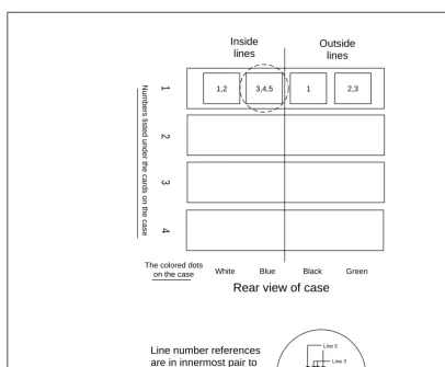
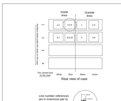
Pin-out of the RJ11 jacks on the back panel of an NTS/8 system
FIGURE A-1: Pin-out of the RJ11 jacks on the back panel on an NTS/8 system
Numbers listed under the cards on the case
Green Black
Blue White The colored dots
on the case
Outside lines Inside
lines
1
3,4,5
1,2 1 2,3
23
4
Line 5
Line 4 Line 3
Line number references are in innermost pair to outermost pair order. For example, the pin-out of the jack circled above is:
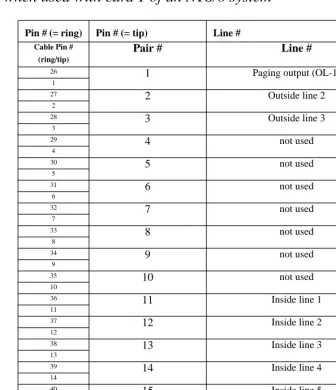
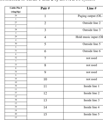
Pin-out of the punch down block (66-block) and RJ11-to-50-pin cable
PN3102 when used with card 1 of an NTS/8 system
Pin # (= ring) Pin # (= tip) Line #
Cable Pin # (ring/tip)
Pair #
Line #
26
1
Paging output (OL-1)1
27
2
Outside line 22
28
3
Outside line 33
29
4
not used4
30
5
not used5
31
6
not used6
32
7
not used7
33
8
not used8
34
9
not used9
35
10
not used10
36
11
Inside line 111
37
12
Inside line 212
38
13
Inside line 313
39
14
Inside line 414
40
15
Inside line 515
41
16
not used16
42
17
not used17
TABLE A-3: Pin-out of the punch down block (66-block) and RJ11-to-50-pin cable PN3102
43
18
not used 1844
19
not used19
45
20
not used20
46
21
not used21
47
22
not used22
48
23
not used23
49
24
not used24
50
25
not used25
Pin # (= ring) Pin # (= tip) Line #
TABLE A-3: Pin-out of the punch down block (66-block) and RJ11-to-50-pin cable PN3102
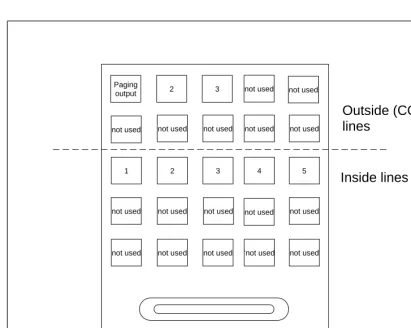
Break-out of the mini patch panel when used with an NTS/8 system and
cable PN3102
FIGURE A-2: Break-out of the mini patch panel when used with
an NTS/8 system and cable PN3102
Paging output
1
2
not used
2
3
not used
3
not used
4
not used
5
not used not used not used ‘not used not used
50-pin connector
Outside (CO)
lines
Inside lines
not used not used
not used
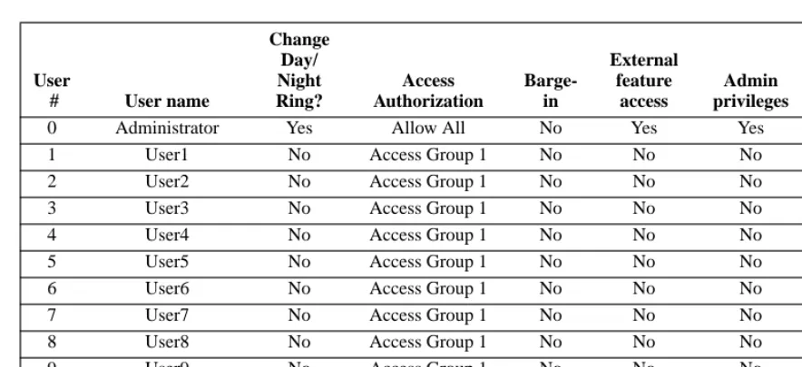
Default system configuration for an NTS/8 system
User
# User name
Change Day/ Night Ring? Access Authorization Barge-in External feature access Admin privileges Initial password
0 Administrator Yes Allow All No Yes Yes 1000
1 User1 No Access Group 1 No No No 1001
2 User2 No Access Group 1 No No No 1002
3 User3 No Access Group 1 No No No 1003
4 User4 No Access Group 1 No No No 1004
5 User5 No Access Group 1 No No No 1005
99 Operator Yes Access Group 1 No No No 1099
TABLE A-4: Telephone users
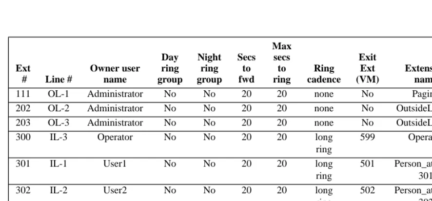
Ext
# Line #
Owner user name Day ring group Night ring group Secs to fwd Max secs to ring Ring cadence Exit Ext (VM) Extension name In PB
111 OL-1 Administrator No No 20 20 none No Paging Yes 202 OL-2 Administrator No No 20 20 none No OutsideLine_2 Yes 203 OL-3 Administrator No No 20 20 none No OutsideLine_3 Yes
300 IL-3 Operator No No 20 20 long
ring
599 Operator Yes
301 IL-1 User1 No No 20 20 long
ring
501 Person_at_Ext_ 301
Yes
302 IL-2 User2 No No 20 20 long
ring
502 Person_at_Ext_ 302
Yes
303 IL-3 User3 No No 20 20 long
ring
503 Person_at_Ext_ 303
Yes
304 IL-4 User4 No No 20 20 long
ring
504 Person_at_Ext_ 304
305 IL-5 User5 No No 20 20 long ring
505 Person_at_Ext_ 305
Yes
306 IL-3 Operator No No 20 20 long
ring
599 Operator Yes
307 IL-3 Operator No No 20 20 long
ring
599 Operator Yes
308 IL-3 Operator No No 20 20 long
ring
599 Operator Yes
411 IL-3 Operator No No 20 20 long
ring
599 Operator Yes
611 IL-3 Operator No No 20 20 long
ring
599 Operator Yes
Voice Mail Exten sion Owner User Number Owner User Name Max Message Size in Secs Voice Mail Directory name Max Voice Mail Box Size in MB
Voice Mail Box Phonebook Name In PB? Allow Email
130 0
Adminis-trator
0 /130 10 Day_Attendant_
Msg
No No
131 0
Adminis-trator
0 /131 10 Night_Attendant_ Msg
No No
500 0
Adminis-trator
120 /500 10 Administrator_V MB
Yes No
501 1 User1 120 /501 10 User1_VMB Yes No
502 2 User2 120 /502 10 User2_VMB Yes No
503 3 User3 120 /503 10 User3_VMB Yes No
504 4 User4 120 /504 10 User4_VMB Yes No
505 5 User5 120 /505 10 User5_VMB Yes No
599 99 Operator 120 /599 30 Operator_VMB Yes No
TABLE A-6: System voice mail boxes
Ext
# Line #
Owner user name Day ring group Night ring group Secs to fwd Max secs to ring Ring cadence Exit Ext (VM) Extension name In PB
Line Number Line Type Day Action Night Action Hold Music? Access Auth Group Secure Line (no barge-in or beeps)? Always Decode Caller-ID? Centrex/ CLASS/ Normal Line
Outside Line 1 Paging Line No Action
No Action
No Lockout Group 1
No No Normal
Outside Line 2 Outside Line 120 121 Yes Lockout Group 1
No No Normal
Outside Line 3 Outside Line 120 121 Yes Lockout Group 1
No No Normal
TABLE A-7: System outside line configuration
Line Number Line Type
Day Action Night Action Hold Music? Access Auth Group Secure Line (no barge-in or beeps)? Seize Group
Inside Line 1-Inside Line 5
Inside Line Dial Tone Dial Tone No Lockout Group 1 No All Lines
TABLE A-8: System inside line configuration
# Digits in extension 3 # Digits in password 4 # Digit in Ring Group 1 Max Hold Stack Depth 3 Energy Detect Threshold 150
Max # of Conferences 2
Access authorization
group number Type Area codes (or 011)
1 Deny 900
2 Allow 800 411 911 011
TABLE A-10: Access authorization groups
Auto attendant extension Program name
120 Day_Program.aa
121 Night_Program.aa
TABLE A-11: Auto attendant programs
Name Seize Order
All Lines Outside Lines OL-3, OL-2
TABLE A-12: Outside line seize order
Group number Inside lines in group
0 Lines IL-1, IL-2, IL-3, IL-4, IL-5
1 Lines OL-1
TABLE A-13: Ring groups
Operator extension 300 Lowest park orbit 100 Highest park orbit 110 Dialing Timeout (secs) 15
Dial Tone Timeout (secs) 90 Busy Signal Timeout (secs) 60 Reminder Tone Timeout (secs) 45 Voice Mail Exclusive Access No CPC Delay (secs) 1 Audio Compression Constant 650 Central Office Hook Flash Time (ms) 750 Conference Time Limit (Min) 30
Exit Voice Mail Extension 120 Voice Mail Waiting Indicator Refresh
Time (minutes)
20
Play Second Standard VM Greeting Yes
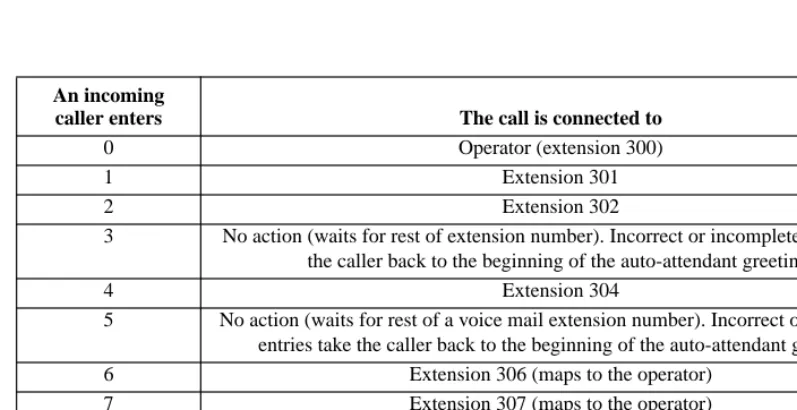
An incoming
caller enters The call is connected to
0 Operator (extension 300)
1 Extension 301
2 Extension 302
3 No action (waits for rest of extension number). Incorrect or incomplete entries take the caller back to the beginning of the auto-attendant greeting.
4 Extension 304
5 No action (waits for rest of a voice mail extension number). Incorrect or incomplete entries take the caller back to the beginning of the auto-attendant greeting. 6 Extension 306 (maps to the operator)
7 Extension 307 (maps to the operator) 8 Extension 308 (maps to the operator)
9 Operator (extension 300)
* Operator (extension 300)
# Operator (extension 300)
APPENDIX B
NTS/16-specific information
Lines connected when AC power is removed from the NTS/16 system
Outside line During AC power lost, connects to
outside line 1 (used as paging output in the default configuration)
inside line 1
outside line 2 inside line 3 outside line 3 inside line 4 outside line 4 (used as the hold music input in the
default configuration)
inside line 6
outside line 5 inside line 8 outside line 6 inside line 9
Wiring worksheet for an NTS/16 system running the default configuration
Inside
line Name of user(s) (fill in)
Default user number
Default extension
number
Default voice mail
extension
Default password
During AC power-down,
connects to:
1 1 301 501 1001 paging output
2 2 302 502 1002 none
3 99 300 (operator) 599 1099 outside line 2
4 4 304 504 1004 outside line 3
5 5 305 505 1005 none
6 6 306 506 1006 hold music input
7 7 307 507 1007 none
8 8 308 508 1008 outside line 5
9 9 309 509 1009 outside line 6
10 10 310 510 1010 none
Pin-out of the RJ11 jacks on the back panel of an NTS/16 system
FIGURE B-1: Pin-out of the RJ11 jacks on the back panel of an NTS/16 system
Numbers listed under the cards on the case
Green Black
Blue White The colored dots
on the case
Outside lines Inside
lines
1
3,4,5
1,2 1 2,3
8,9,10
6,7 4 5,6
23
4
Line 5
Line 4 Line 3
Line number references are in innermost pair to outermost pair order. For example, the pin-out of the jack circled above is:
Pin-out of punch down block (66-block) with RJ11-to-50-pin cable
PN3102 connected to cards 1 and 2 of an NTS/16 system
Cable Pin # (ring/tip)
Pair #
Line #
26
1
Paging output (OL-1)1
27
2
Outside line 22
28
3
Outside line 33
29
4
Hold music input (OL-4)4
30
5
Outside line 55
31
6
Outside line 66
32
7
not used7
33
8
not used8
34
9
not used9
35
10
not used10
36
11
Inside line 111
37
12
Inside line 212
38
13
Inside line 313
39
14
Inside line 414
40
15
Inside line 515
41
16
Inside line 616
42
17
Inside line 717
43
18
Inside line 818
TABLE B-3: Pin-out of the punch down block (66-block) with RJ11-to-50-pin cable PN3102 when used
44
19
Inside line 9 1945
20
Inside line 1020
46
21
not used21
47
22
not used22
48
23
not used23
49
24
not used24
50
25
not used25
TABLE B-3: Pin-out of the punch down block (66-block) with RJ11-to-50-pin cable PN3102 when used
Break-out of the mini patch panel when used with an NTS/16 system and
cable PN3102
FIGURE B-2: Break-out of the mini patch panel when used with
an NTS/16 system and cable PN3102 (cards 1-2)
Paging output
6
1
6
2
not used
2
7
3
not used
3
8
Hold music input
not used
4
9
5
not used
5
10
not used not used not used ‘not used not used
50-pin connector
Outside (CO)
lines
Default system configuration for an NTS/16 system
User
# User name
Change Day/ Night Ring? Access Authorization Barge-in External feature access Admin privileges Initial password
0 Administrator Yes Allow All No Yes Yes 1000
1 User1 No Access Group 1 No No No 1001
2 User2 No Access Group 1 No No No 1002
3 User3 No Access Group 1 No No No 1003
4 User4 No Access Group 1 No No No 1004
5 User5 No Access Group 1 No No No 1005
6 User6 No Access Group 1 No No No 1006
7 User7 No Access Group 1 No No No 1007
8 User8 No Access Group 1 No No No 1008
9 User9 No Access Group 1 No No No 1009
10 User10 No Access Group 1 No No No 1010
99 Operator Yes Access Group 1 No No No 1099
TABLE B-4: Telephone users
Ext
# Line #
Owner user name Day ring group Night ring group Secs to fwd Max secs to ring Ring cadence Voice mail ext to
fwd Extension name In PB
111 OL-1 Administra-tor
No No 20 20 none No Paging Yes
202 OL-2 Administra-tor
No No 20 20 none No OutsideLine_2 Yes
203 OL-3 Administra-tor
No No 20 20 none No OutsideLine_3 Yes
205 OL-5 Administra-tor
206 OL-6 Administra-tor
No No 20 20 none No OutsideLine_6 Yes
300 IL-3 Operator No No 20 20 long
ring
599 Operator Yes
301 -310 Il1 -IL-10 User1 -User10
No No 20 20 long
ring 501-510 Person_at_Ext_310 Yes
411 IL-3 Operator No No 20 20 long
ring
599 Operator Yes
611 IL-3 Operator No No 20 20 long
ring
599 Operator Yes
Voice Mail Exten sion Owner User Number Owner User Name Max Message Size in Secs Voice Mail Directory name Max Voice Mail Box Size in MB
Voice Mail Box Phonebook Name In PB? Allow email
130 0 Administra-tor
0 /130 10 Day_Attendant_
Msg
No No
131 0 Administra-tor
0 /131 10 Night_Attendant
_Msg
No No
500 0 Administra-tor
120 /500 10 Administrator_V MB Yes No 501-510 1 User1-User 10
120 /501 - /510 10 User1_VMB-User10_VMB
Yes No
599 99 Operator 120 /599 30 Operator_VMB Yes No
TABLE B-6: System voice mail boxes
Ext
# Line #
Owner user name Day ring group Night ring group Secs to fwd Max secs to ring Ring cadence Voice mail ext to
fwd Extension name In PB
Line Number Line Type Day Action Night Action Hold Music? Access Auth Group Secure Line (no barge-in or beeps)? Always Decode Caller-ID? Centrex/ CLASS/ Normal Line
Outside Line 1 Paging Line No Action
No Action
No Lockout Group 1
No No Normal
Outside Line 2 Outside Line 120 121 Yes Lockout Group 1
No No Normal
Outside Line 3 Outside Line 120 121 Yes Lockout Group 1
No No Normal
Outside Line 4 Hold Music Input No Action No Action -- Lockout Group 1
No No Normal
Outside Line 5-Outside Line 6
Outside Line 120 121 Yes Lockout Group 1
No No Normal
TABLE B-7: System outside line configuration
Line Number Line Type
Day Action Night Action Hold Music? Access Auth Group Secure Line (no barge-in or beeps)? Seize Group
Inside Line 1-Inside Line 10
Inside Line Dial Tone Dial Tone No Lockout Group 1
No All
Lines
TABLE B-8: System inside line configuration
# Digits in extension 3 # Digits in password 4 # Digit in Ring Group 1 Max Hold Stack Depth 3 Energy Detect Threshold 150
Access authorization
group number Type Area codes (or 011)
1 Deny 900
2 Allow 800 411 911 011
TABLE B-10: Access authorization groups
Auto attendant extension Program name
120 Day_Program.aa
121 Night_Program.aa
TABLE B-11: Auto attendant programs
Name Outside line size order
All Lines Outside Lines OL-6, OL-5, OL-3, OL-2
TABLE B-12: Outside line seize order
Group number Inside lines in group
0 Lines IL-1, IL-2, IL-3, IL-4, IL-5, IL-6, IL-7, IL-8, IL-9, IL-10
1 Lines OL-1
TABLE B-13: Ring groups
Operator extension 300 Lowest park orbit 100 Highest park orbit 110 Dialing Timeout (secs) 15
:
Dial Tone Timeout (secs) 90 Busy Signal Timeout (secs) 60 Reminder Tone Timeout (secs) 45 Voice Mail Exclusive Access No CPC Delay (secs) 1 Audio Compression Constant 650 Central Office Hook Flash Time (ms) 750 Conference Time Limit (Min) 30
Exit Voice Mail Extension 120 Voice Mail Waiting Indicator Refresh
Time (minutes)
20
Play Second Standard VM Greeting Yes
An incoming
caller enters The call is connected to
0 Operator (extension 300)
1 Extension 301
2 Extension 302
3 No action (waits for rest of extension number). Incorrect or incomplete entries take the caller back to the beginning of the auto-attendant greeting.
4 Extension 304
5 No action (waits for rest of a voice mail extension number). Incorrect or incomplete entries take the caller back to the beginning of the auto-attendant greeting.
6 Extension 306
7 Extension 307
8 Extension 308
9 Operator (extension 300)
* Operator (extension 300)
# Operator (extension 300)
APPENDIX C
NTS/24-specific information
Lines connected when AC power is removed from the NTS/24 system
Outside line During AC power lost, connects to
outside line 1 (used as paging output in the default configuration)
inside line 1
outside line 2 inside line 3 outside line 3 inside line 4 outside line 4 (used as the hold music input in the
default configuration)
inside line 6
outside line 5 inside line 8 outside line 6 inside line 9 outside line 7 inside line 11 outside line 8 inside line 13 outside line 9 inside line 14
Wiring worksheet for an NTS/24 system running the default configuration
Inside
line Name of user(s) (fill in)
Default user number
Default extension
number
Default voice mail
extension
Default password
During AC power-down,
connects to:
1 1 301 501 1001 paging output
2 2 302 502 1002 none
3 99 300 (operator) 599 1099 outside line 2
4 4 304 504 1004 outside line 3
5 5 305 505 1005 none
6 6 306 506 1006 hold music input
7 7 307 507 1007 none
8 8 308 508 1008 outside line 5
9 9 309 509 1009 outside line 6
10 10 310 510 1010 none
11 11 311 511 1011 outside line 7
12 12 312 512 1012 none
13 13 313 513 1013 outside line 8
14 14 314 514 1014 outside line 9
15 15 315 515 1015 none
Pin-out of the RJ11 jacks on the back panel of an NTS/24 system
FIGURE C-1: Pin-out of the RJ11 jacks on the back panel of an NTS/24 system
Numbers listed under the cards on the case
Green Black
Blue White The colored dots
on the case
Outside lines Inside
lines
1
3,4,5
1,2 1 2,3
8,9,10
6,7 4 5,6
23
4
Line 5
Line 4 Line 3
Line number references are in innermost pair to outermost pair order. For example, the pin-out of the jack circled above is:
Rear view of case
13,14,15
Pin-out of the punch down block (66-block) with RJ11-to-50-pin cable
PN3102 when used with cards 1, 2, and 3 of an NTS/24 system
Cable Pin # (ring/tip)
Pair #
Line #
26
1
Paging output (OL-1) 127
2
Outside line 2 228
3
Outside line 3 329
4
Hold music input (OL-4) 430
5
Outside line 5 531
6
Outside line 6 632
7
Outside line 7 733
8
Outside line 8 834
9
Outside line 9 935
10
not used10
36
11
Inside line 1 1137
12
Inside line 2 1238
13
Inside line 3 1339
14
Inside line 4 1440
15
Inside line 5 1541
16
Inside line 6 1642
17
Inside line 7 1743
18
Inside line 8 18TABLE C-3: Pin-out of the punch down block (66-block) with RJ11-to-50-pin cable PN3102
44
19
Inside line 9 1945
20
Inside line 10 2046
21
Inside line 11 2147
22
Inside line 12 2248
23
Inside line 13 2349
24
Inside line 14 2450
25
Inside line 15 25Cable Pin # (ring/tip)
Pair #
Line #
TABLE C-3: Pin-out of the punch down block (66-block) with RJ11-to-50-pin cable PN3102
Break-out of the mini patch panel when used with an NTS/24 system and
cable PN3102
FIGURE C-2: Break-out of the mini patch panel when used with
an NTS/24 system and cable PN3102 (cards 1-3)
Paging output
6
1
6
2
7
2
7
3
8
3
8
Hold music input
9
4
9
5
not used
5
10
11 12 13 14 15
50-pin connector
Outside (CO)
lines
Default system configuration for an NTS/24 system
User
# User name
Change Day/ Night Ring? Access Authorization Barge-in External feature access Admin privileges Initial password
0 Administrator Yes Allow All No Yes Yes 1000
1 User1 No Access Group 1 No No No 1001
2 User2 No Access Group 1 No No No 1002
3 User3 No Access Group 1 No No No 1003
4 User4 No Access Group 1 No No No 1004
5 User5 No Access Group 1 No No No 1005
6 User6 No Access Group 1 No No No 1006
7 User7 No Access Group 1 No No No 1007
8 User8 No Access Group 1 No No No 1008
9 User9 No Access Group 1 No No No 1009
10 User10 No Access Group 1 No No No 1010
11 User11 No Access Group 1 No No No 1011
12 User12 No Access Group 1 No No No 1012
13 User13 No Access Group 1 No No No 1013
14 User14 No Access Group 1 No No No 1014
15 User15 No Access Group 1 No No No 1015
99 Operator Yes Access Group 1 No No No 1099
TABLE C-4: Telephone users
Ext # Line #
Owner user name Day ring group Night ring group Secs to fwd Max secs to ring Ring caden ce Voice mail ext to
fwd Extension name In PB
111 OL-1 Administrator No No 20 20 --- No Paging Yes
205-209
OL-5 - OL-9
Administrator No No 20 20 --- No OutsideLine_5 -OutsideLine_9
Yes
300 IL-3 Operator No No 20 20 long
ring
599 Operator Yes
301-315 Il1 -IL-15 User1 -User15
No No 20 20 long
ring 501-515 Person_at_Ext_301 -Person_at Ext_315 Yes
411 IL-3 Operator No No 20 20 long
ring
599 Operator Yes
611 IL-3 Operator No No 20 20 long
ring
599 Operator Yes
Voice Mail Exten sion Owner User Number Owner User Name Max Message Size in Secs Voice Mail Directory name Max Voice Mail Box Size in MB
Voice Mail Box Phonebook Name In PB? Allow email
130 0 Administra-tor
0 /130 10 Day_Attendant_
Msg
No No
131 0 Administra-tor
0 /131 10 Night_Attendant
_Msg
No No
500 0 Administra-tor
120 /500 10 Administrator_ VMB
Yes No
501-515
1 - 15 User1-User15
120 /501 - /515 10 User1_VMB-User15_VMB
Yes No
599 99 Operator 120 /599 30 Operator_VMB Yes No
TABLE C-6: System voice mail boxes
Ext # Line #
Owner user name Day ring group Night ring group Secs to fwd Max secs to ring Ring caden ce Voice mail ext to
fwd Extension name In PB
Line Number Line Type Day Action Night Action Hold Music? Access Auth Group Secure Line (no barge-in or beeps)? Always Decode Caller-ID? Centrex/ CLASS/ Normal Line
Outside Line 1 Paging Line No Action
No Action
No Lockout Group 1
No No Normal
Outside Line 2 Outside Line 120 121 Yes Lockout Group 1
No No Normal
Outside Line 3 Outside Line 120 121 Yes Lockout Group 1
No No Normal
Outside Line 4 Hold Music Input No Action No Action --- Lockout Group 1
No No Normal
Outside Line 5-Outside Line 9
Outside Line 120 121 Yes Lockout Group 1
No No Normal
TABLE C-7: System outside line configuration
Line Number Line Type
Day Action Night Action Hold Music? Access Auth Group Secure Line (no barge-in or beeps)? Seize Group?
Inside Line 1-Inside Line 15
Inside Line Dial Tone Dial Tone No Lockout Group 1
No all lines
TABLE C-8: System inside line configuration
# Digits in extension 3 # Digits in password 4 # Digit in Ring Group 1 Max Hold Stack Depth 3 Energy Detect Threshold 150
Access authorization
group number Type Area codes (or 011)
1 Deny 900
2 Allow 800 411 911 011
TABLE C-10: Access authorization groups
Auto attendant extension Program name
120 Day_Program.aa
121 Night_Program.aa
TABLE C-11: Auto attendant programs
Name Outside line size order
All Lines Outside Lines OL-9, OL-8, OL-7, OL-6, OL-5, OL-3, OL-2
TABLE C-12: Outside line seize order
Group number Inside lines in group
0 Lines IL-1, IL-2, IL-3, IL-4, IL-5, IL-6, IL-7, IL-8, IL-9, IL-10, IL-11, IL-12, IL-13, IL-14, IL-15
1 Lines OL-1
TABLE C-13: Ring groups
Operator extension 300 Lowest park orbit 100 Highest park orbit 110
:
Dialing Timeout (secs) 15 Dial Tone Timeout (secs) 90 Busy Signal Timeout (secs) 60 Reminder Tone Timeout (secs) 45 Voice Mail Exclusive Access No CPC Delay (secs) 1 Audio Compression Constant 650 Central Office Hook Flash Time (ms) 750 Conference Time Limit (Min) 30
Exit Voice Mail Extension 120 Voice Mail Waiting Indicator Refresh
Time (minutes)
20
Play Second Standard VM Greeting Yes
An incoming
caller enters The call is connected to
0 Operator (extension 300)
1 Extension 301
2 Extension 302
3 No action (waits for rest of extension number). Incorrect or incomplete entries take the caller back to the beginning of the auto-attendant greeting.
4 Extension 304
5 No action (waits for rest of a voice mail extension number). Incorrect or incomplete entries take the caller back to the beginning of the auto-attendant greeting.
6 Extension 306
7 Extension 307
8 Extension 308
9 Operator (extension 300)
* Operator (extension 300)
# Operator (extension 300)
APPENDIX D
NTS/32-specific information
Lines connected when AC power is removed from the NTS/32 system
Outside line During AC power lost, connects to
outside line 1 (used as paging output in the default configuration)
inside line 1
outside line 2 inside line 3 outside line 3 inside line 4 outside line 4 (used as the hold music input in the
default configuration)
inside line 6
outside line 5 inside line 8 outside line 6 inside line 9 outside line 7 inside line 11 outside line 8 inside line 13 outside line 9 inside line 14 outside line 10 inside line 16 outside line 11 inside line 18 outside line 12 inside line 19
Wiring worksheet for an NTS/32 system running the default configuration
Inside
line Name of user(s) (fill in)
Default user number
Default extension
number
Default voice mail
extension
Default password
During AC power-down,
connects to:
1 1 301 501 1001 paging output
2 2 302 502 1002 none
3 99 300 (operator) 599 1099 outside line 2
4 4 304 504 1004 outside line 3
5 5 305 505 1005 none
6 6 306 506 1006 hold music
input
7 7 307 507 1007 none
8 8 308 508 1008 outside line 5
9 9 309 509 1009 outside line 6
10 10 310 510 1010 none
11 11 311 511 1011 outside line 7
12 12 312 512 1012 none
13 13 313 513 1013 outside line 8
14 14 314 514 1014 outside line 9
15 15 315 515 1015 none
16 16 316 516 1016 outside line 10
17 17 317 517 1017 none
18 18 318 518 1018 outside line 11
19 19 319 519 1019 outside line 12
20 20 320 520 1020 none
Pin-out of the RJ11 jacks on the back panel of an NTS/32 system
FIGURE D-1: Pin-out of the RJ11 jacks on the back panel of an NTS/32 system
Numbers listed under the cards on the case
Green Black
Blue White The colored dots
on the case
Outside lines Inside
lines
1
3,4,5
1,2 1 2,3
8,9,10
6,7 4 5,6
23
4
Line 5
Line 4 Line 3
Line number references are in innermost pair to outermost pair order. For example, the pin-out of the jack circled above is:
Rear view of case
13,14,15
11,12 7 8,9
18,19,20
Pin-out of the punch down block (66-block) of RJ11-to-50-pin cable
PN3102 when used with cards 1, 2, and 3 of an NTS/32 system
Cable Pin # (ring/tip)
Pair #
Line #
26
1
Paging output (OL-1)1
27
2
Outside line 22
28
3
Outside line 33
29
4
Hold music input (OL-4)4
30
5
Outside line 55
31
6
Outside line 66
32
7
Outside line 77
33
8
Outside line 88
34
9
Outside line 99
35
10
not used10
36
11
Inside line 111
37
12
Inside line 212
38
13
Inside line 313
39
14
Inside line 414
40
15
Inside line 515
41
16
Inside line 616
42
17
Inside line 717
43
18
Inside line 818
TABLE D-3: Pin-out of the punch down block (66-block) of RJ11-to-50-pin cable PN3102 when used with
44
19
Inside line 9 1945
20
Inside line 1020
46
21
Inside line 1121
47
22
Inside line 1222
48
23
Inside line 1323
49
24
Inside line 1424
50
25
Inside line 1525
TABLE D-3: Pin-out of the punch down block (66-block) of RJ11-to-50-pin cable PN3102 when used with
Pin-out of the punch down block (66-block) of RJ11-to-50-pin cable
PN3102 when used with card 4 of an NTS/32 system
Cable Pin # (ring/tip)
Pair #
Line #
26
1
Outside Line 101
27
2
Outside line 112
28
3
Outside line 123
29
4
not used4
30
5
not used5
31
6
not used6
32
7
not used7
33
8
not used8
34
9
not used9
35
10
not used10
36
11
Inside line 1611
37
12
Inside line 1712
38
13
Inside line 1813
39
14
Inside line 1914
40
15
Inside line 2015
41
16
not used16
42
17
not used17
43
18
not used18
TABLE D-4: Pin-out of the punch down block (66-block) of RJ11-to-50-pin cable PN3102 when used with
44
19
not used 1945
20
not used20
46
21
not used21
47
22
not used22
48
23
not used23
49
24
not used24
50
25
not used25
TABLE D-4: Pin-out of the punch down block (66-block) of RJ11-to-50-pin cable PN3102 when used with
Break-out of the first mini patch panel when used with an NTS/32 system
and cable PN3102 (cards 1-3)
FIGURE D-2: Break-out of the first mini patch panel when used with
an NTS/32 system and cable PN3102 (card 1-3)
Paging output
6
1
6
2
7
2
7
3
8
3
8
Hold music input
9
4
9
5
not used
5
10
11 12 13 14 15
50-pin connector
Outside (CO)
lines
Break-out of the second mini patch panel when used with an NTS/32
system and second cable PN3102 (card 4)
FIGURE D-3: Break-out of the second mini patch panel when used with
an NTS/32 system and second cable PN3102 (card 4)
10
16
11
17
12
18 19
not used
20
50-pin connector
Outside (CO)
lines
Inside lines
not used not used
not used
not used not used
not used not used
not used
not used not used
not used
not used not used
not used not used
Default system configuration for an NTS/32 system
User
# User name
Change Day/ Night Ring?
Access Authorization
Barge-in
External feature
access
Admin privileges
Initial password
0 Administrator Yes Allow All No Yes Yes 1000
1 User1 No Access Group 1 No No No 1001
2 User2 No Access Group 1 No No No 1002
3 User3 No Access Group 1 No No No 1003
4 User4 No Access Group 1 No No No 1004
5 User5 No Access Group 1 No No No 1005
6 User6 No Access Group 1 No No No 1006
7 User7 No Access Group 1 No No No 1007
8 User8 No Access Group 1 No No No 1008
9 User9 No Access Group 1 No No No 1009
10 User10 No Access Group 1 No No No 1010
11 User11 No Access Group 1 No No No 1011
12 User12 No Access Group 1 No No No 1012
13 User13 No Access Group 1 No No No 1013
14 User14 No Access Group 1 No No No 1014
15 User15 No Access Group 1 No No No 1015
16 User16 No Access Group 1 No No No 1016
17 User17 No Access Group 1 No No No 1017
18 User18 No Access Group 1 No No No 1018
19 User19 No Access Group 1 No No No 1019
20 User20 No Access Group 1 No No No 1020
99 Operator Yes Access Group 1 No No No 1099
Ext
# Line #
Owner user name Day ring group Night ring group Secs to fwd Max secs to ring Ring cadence Voice mail ext to
fwd Extension name In PB
111 OL-1 Administrator No No 20 20 --- No Paging Yes
202 OL-2 Administrator No No 20 20 --- No OutsideLine_2 Yes 203 OL-3 Administrator No No 20 20 --- No OutsideLine_3 No
205-212
OL-5 - OL-18
Administrator No No 20 20 none No OutsideLine_5-OutsideLine_18
No
300 IL-3 Operator No No 20 20 long
ring
599 Operator Yes
301-320 Il1 -IL-20 User1-User20
No No 20 20 long
ring 501-520 Person_at_Ext_301 -Person_at_Ext_320 Yes
411 IL-3 Operator No No 20 20 long
ring
599 Operator Yes
611 IL-3 Operator No No 20 20 long
ring
599 Operator Yes
411 IL-3 Operator No No 20 20 long
ring
599 Operator Yes
611 IL-3 Operator No No 20 20 long
ring
599 Operator Yes
TABLE D-6: System extensions
Voice Mail Exten sion Owner User Number Owner User Name Max Message Size in Secs
Voice Mail Directory name Max Voice Mail Box Size in MB
Voice Mail Box Phonebook Name In PB? Allow email
130 0 Administra-tor
0 /130 10 Day_Attendant_
Msg
No No
500 0 Administra-tor
120 /500 10 Administrator_ VMB
Yes No
501 -520
1 - 20 User1 -User20
120 /501 - /520 10 User1_VMB-User20_VMB
Yes No
599 99 Operator 120 /599 30 Operator_VMB Yes No
Line Number Line Type
Day Action Night Action Hold Music? Access Auth Group Secure Line (no barge-in or beeps)? Always Decode Caller-ID? Centrex/ CLASS/ Normal Line
Outside Line 1 Paging Line No Action
No Action
No Lockout Group 1
No No Normal
Outside Line 2 Outside Line 120 121 Yes Lockout Group 1
No No Normal
Outside Line 3 Outside Line 120 121 Yes Lockout Group 1
No No Normal
Outside Line 4 Hold Music Input No Action No Action --- Lockout Group 1
No No Normal
Outside Line 5-Outside Line 12
Outside Line 120 121 Yes Lockout Group 1
No No Normal
TABLE D-8: System outside line configuration
Line Number Line Type Day Action
Night Action Hold Music? Access Auth Group Secure Line (no barge-in or beeps)? Seize Group?
Inside Line 1-Inside Line 20
Inside Line Dial Tone Dial Tone No Lockout Group 1
No All Lines
TABLE D-9: System inside line configuration
Voice Mail Exten sion Owner User Number Owner User Name Max Message Size in Secs
Voice Mail Directory name Max Voice Mail Box Size in MB
Voice Mail Box Phonebook Name In PB? Allow email
# Digits in extension 3 # Digits in password 4 # Digit in Ring Group 1 Max Hold Stack Depth 3 Energy Detect Threshold 150
Max # of Conferences 2
TABLE D-10: System constants
Access authorization
group number Type Area codes (or 011)
1 Deny 900
2 Allow 800 411 911 011
TABLE D-11: Access authorization groups
Auto attendant extension Program name
120 Day_Program.aa
121 Night_Program.aa
TABLE D-12: Auto attendant programs
Name Outside line size order
All Lines Outside Lines OL-12, OL-11, OL-10, OL-9, OL-8, OL-7, OL-6, OL-5, OL-3, OL-2
:
Group number Inside lines in group
0 Lines IL-1, IL-2, IL-3, IL-4, IL-5, IL-6, IL-7, IL-8, IL-9, IL-10, IL-11, IL-12, IL-13, IL-14, IL-15, IL-16, IL-17, IL-18, IL-19, IL-20
1 Lines OL-1
TABLE D-14: Ring groups
Operator extension 300 Lowest park orbit 100 Highest park orbit 110 Dialing Timeout (secs) 15 Dial Tone Timeout (secs) 90 Busy Signal Timeout (secs) 60 Reminder Tone Timeout (secs) 45 Voice Mail Exclusive Access No CPC Delay (secs) 1 Audio Compression Constant 650 Central Office Hook Flash Time (ms) 750 Conference Time Limit (Min) 30
Exit Voice Mail Extension 120 Voice Mail Waiting Indicator Refresh
Time (minutes)
20
Play Second Standard VM Greeting Yes
TABLE D-15: System globals
An incoming
caller enters The call is connected to
0 Operator (extension 300)
1 Extension 301
2 Extension 302
3 No action (waits for rest of extension number). Incorrect or incomplete entries take the caller back to the beginning of the auto-attendant greeting.
4 Extension 304
5 No action (waits for rest of a voice mail extension number). Incorrect or incomplete entries take the caller back to the beginning of the auto-attendant greeting.
6 Extension 306
7 Extension 307
8 Extension 308
9 Operator (extension 300)
* Operator (extension 300)
# Operator (extension 300)
An incoming
caller enters The call is connected to
APPENDIX E
NTS/40-specific information
Lines connected when AC power is removed from the NTS/40 system
Outside line During AC power lost, connects to
outside line 1 (used as paging output in the default configuration)
inside line 1
outside line 2 inside line 3 outside line 3 inside line 4 outside line 4 (used as the hold music input in the
default configuration)
inside line 6
outside line 5 inside line 8 outside line 6 inside line 9 outside line 7 inside line 11 outside line 8 inside line 13 outside line 9 inside line 14 outside line 10 inside line 16 outside line 11 inside line 18 outside line 12 inside line 19 outside line 13 inside line 21
Wiring worksheet for an NTS/40 system running the default configuration
outside line 14 inside line 23 outside line 15 inside line 24
Inside
line Name of user(s) (fill in)
Default user number
Default extension
number
Default voice mail
extension
Default password
During AC power-down,
connects to:
1 1 301 501 1001 paging output
2 2 302 502 1002 none
3 99 300 (operator) 599 1099 outside line 2
4 4 304 504 1004 outside line 3
5 5 305 505 1005 none
6 6 306 506 1006 hold music
input
7 7 307 507 1007 none
8 8 308 508 1008 outside line 5
9 9 309 509 1009 outside line 6
10 10 310 510 1010 none
11 11 311 511 1011 outside line 7
12 12 312 512 1012 none
13 13 313 513 1013 outside line 8
14 14 314 514 1014 outside line 9
15 15 315 515 1015 none
16 16 316 516 1016 outside line 10
17 17 317 517 1017 none
18 18 318 518 1018 outside line 11
19 19 319 519 1019 outside line 12
20 20 320 520 1020 none
21 21 321 521 1021 outside line 13
TABLE E-2: Wiring worksheet for NTS/40 systems, default configuration
Outside line During AC power lost, connects to
22 22 322 522 1022 none
23 23 323 523 1023 outside line 14
24 24 324 524 1024 outside line 15
25 25 325 525 1025 none
Inside
line Name of user(s) (fill in)
Default user number
Default extension
number
Default voice mail
extension
Default password
During AC power-down,
connects to:
Pin-out of the RJ11 jacks on the back of an NTS/40 system
FIGURE E-1: Pin-out of the RJ11 jacks on the back on an NTS/40 system
Numbers listed under the cards on the case
Outside lines Inside
lines
1
3,4,5
1,2 1 2,3
8,9,10
6,7 4 5,6
2
Green Black
Blue White The colored dots
on the case
Rear view of case
Line 5
Line 4 Line 3
Line number references are in innermost pair to outermost pair order. For example, the pin-out of the jack circled above is:
34
13,14,15
11,12 7 8,9
18,19,20
16,17 10 11,12
Pin-out of the punch down block (66-block) of RJ11-to-50-pin cable
PN3102 when used with cards 1, 2, and 3 of an NTS/40 system
Cable Pin # (ring/tip)
Pair #
Line #
26
1
Paging output (OL-1)1
27
2
Outside line 22
28
3
Outside line 33
29
4
Hold music input (OL-4)4
30
5
Outside line 55
31
6
Outside line 66
32
7
Outside line 77
33
8
Outside line 88
34
9
Outside line 99
35
10
not used10
36
11
Inside line 111
37
12
Inside line 212
38
13
Inside line 313
39
14
Inside line 414
40
15
Inside line 515
41
16
Inside line 616
42
17
Inside line 717
43
18
Inside line 844
19
Inside line 9 1945
20
Inside line 1020
46
21
Inside line 1121
47
22
Inside line 1222
48
23
Inside line 1323
49
24
Inside line 1424
50
25
Inside line 1525
TABLE E-3: Pin-out of the punch down block (66-block) of RJ11-to-50-pin cable PN3102 when used with
Pin-out of the punch down block (66-block) of RJ11-to-50-pin cable
PN3102 when used with cards 4 and 5 of an NTS/40 system
Cable Pin # (ring/tip)
Pair #
Line #
26
1
Outside Line 101
27
2
Outside line 112
28
3
Outside line 123
29
4
Outside Line 134
30
5
Outside line 145
31
6
Outside line 156
32
7
not used7
33
8
not used8
34
9
not used9
35
10
not used10
36
11
Inside line 1611
37
12
Inside line 1712
38
13
Inside line 1813
39
14
Inside line 1914
40
15
Inside line 2015
41
16
Inside line 2116
42
17
Inside line 2217
43
18
Inside line 2344
19
Inside line 24 1945
20
Inside line 2520
46
21
not used21
47
22
not used22
48
23
not used23
49
24
not used24
50
25
not used25
TABLE E-4: Pin-out of the punch down block (66-block) of RJ11-to-50-pin cable PN3102 when used with
Break-out of the first mini patch panel when used with an NTS/40 system
and cable PN3102 (cards 1-3)
FIGURE E-2: Break-out of the first mini patch panel when used with
an NTS/40 system and cable PN3102 (cards 1-3)
Paging output
6
1
6
2
7
2
7
3
8
3
8
Hold music input
9
4
9
5
not used
5
10
11 12 13 14 15
50-pin connector
Outside (CO)
lines
Break-out of the second mini patch panel when used with an NTS/40
system and cable PN3102 (cards 4-5)
FIGURE E-3: Break-out of the second mini patch panel when used with
an NTS/40 system and cable PN3102 (cards 4-5)
10
15
16
21
11
17
22
12
18
23
13
19
24
14
not used
20
25
50-pin connector
Outside (CO)
lines
Inside lines
not used not used
not used
not used not used
not used not used
Default system configuration for an NTS/40 system
User
# User name
Change Day/ Night Ring?
Access Authorization
Barge-in
External feature
access
Admin privileges
Initial password
0 Administrator Yes Allow All No Yes Yes 1000
1 User1 No Access Group 1 No No No 1001
2 User2 No Access Group 1 No No No 1002
3 User3 No Access Group 1 No No No 1003
4 User4 No Access Group 1 No No No 1004
5 User5 No Access Group 1 No No No 1005
6 User6 No Access Group 1 No No No 1006
7 User7 No Access Group 1 No No No 1007
8 User8 No Access Group 1 No No No 1008
9 User9 No Access Group 1 No No No 1009
10 User10 No Access Group 1 No No No 1010
11 User11 No Access Group 1 No No No 1011
12 User12 No Access Group 1 No No No 1012
13 User13 No Access Group 1 No No No 1013
14 User14 No Access Group 1 No No No 1014
15 User15 No Access Group 1 No No No 1015
16 User16 No Access Group 1 No No No 1016
17 User17 No Access Group 1 No No No 1017
18 User18 No Access Group 1 No No No 1018
19 User19 No Access Group 1 No No No 1019
20 User20 No Access Group 1 No No No 1020
21 User21 No Access Group 1 No No No 1021
22 User22 No Access Group 1 No No No 1022
23 User23 No Access Group 1 No No No 1023
24 User24 No Access Group 1 No No No 1024
25 User25 No Access Group 1 No No No 1025