Design and implementation of SVPWM based
Voltage Source Converters with Extended Selective
Harmonic Compensation
M s CH.Nandini1
P.G Scholar
M r.Madhu Babu.T2
Assistant Professor
M r C V Jayapal Reddy3 Assistant Professor [email protected]
Department of Electrical and Electronics Engineering
Teegala Krishna Reddy Engineering College,Hyderabad,Telangana.500097
A b stract- The rapid development of high switching frequency p ower electronics in t he p ast decade leads t owards wider ap p licat ion of volt age source convert ers in AC p ower generation. Therefore, this prompts the need for a modulat ion t echnique with less total harmonic distortion, fewer swit ching losses, and wider linear modulation range. Space vect or p ulse width modulation (SVPWM ) p rovides a bet t er t echnique compared to the more commonly used PWM or sinusoidal PWM (SPWM) techniques because of t heir easier digit al realization and better DC bus ut iliz at io n. T he sp ace vect or control algorithm in VSC provides different functions such as reactive power compensation for Power fact or correct ion, Harmonic Elimination, Load balancing for both linear and non -linear loads. Also, selective harmonic compensat ion (SHC ) is p ossible in order t o avoid p ossible resonances at given frequencies. It can be imp lement ed by using M AT LAB/SIM ULINK Soft ware.
Keywords—Voltage source converter, Space vector pulse wit h modulat ion,Select ive Harmonic Comp ensat ion (SHC).
I. INTRODUCTION
Harmonics is the main issue with inverters. Though the sinusoidal and space vector types of PWM (SPWM & SVPWM) used in inverters [1] help reduce harmonics they incur high switching losses. Therefore the selective harmonic elimination is nowadays coming up as an alternative for SPWM and SVPWM. In square wave inverters usually with single pulse scheme all the odd harmonics are present. However with SVPWM and SPWM techniques the harmonics are eliminated up to the switching frequency [2]. Space Vector Modulation (SVM) technique was originally developed as vector approach to pulse-width modulation (PWM) for three-phase inverters. This technique confines space vectors to be applied according to region where the output voltage vector is located [3-4]. The determination of switching instants may be achieved using space vector modulation technique based on the representation of switching vectors in α-β plane. Space Vector Modulation increases the
output capability of Sinusoidal PWM (SPWM) without distorting output voltage waveform; and prevents un-necessary switching.
Voltage Source Inverters (VSI) have proven to be more efficient, cost effective, less space, faster dynamic response for rapid changes in speed or torque and be capable of running the motor without de-rating [5]. A typical three phase VSI consist of a diode rectifier (SCR bridge rectifiers in case of variable DC output voltages) which converts AC line to DC, a parallel capacitor DC Link which stores the energy for the system and regulates the DC bus voltages, an inverter is consist of insulated gate bipolar transistors (IGBTs) which provides variable frequency output depending upon the applied reference voltage and switching technique [6].
In selective harmonics elimination only the lower order harmonics typically the 5th 7th 11th and the 13th order
II SYSTEM DESCRIPTION
Fig.1 shows a three-phase grid-connected voltage source converter with an LCL-filter, whose parameters used for design are summarized in Table 3.1. For simplicity, the dc-link voltage Vdc of the converter can be treated as constant, while its
grid synchronization bandwidth can be assumed as smaller than the grid fundamental frequency to avoid unintentional low-frequency instability [29]. This structure has earlier been shown by [23] to have an inherent damping effect even when only a single control loop is used for regulating the grid current
i
2.The only condition demanded is for the LCL resonance frequency to be placed above one-sixth of the system control frequency fs/6, which in [23], is named as the critical frequency.
This region is however not attractive because of its poorer switching harmonic filtering, which in general, compromises the purpose of having an LCL filter [23]. Moreover, the wide variation of grid impedance in weak grids may shift the LCL resonance frequency in a wide spectrum across fs/6, giving rise
to instability if no external active damping is employed.
Fig.1. Three-phase grid-connected voltage source converter with an LCL filter.
Table 1
Main Parameters of Grid-Connected Converter
To illustrate where the external active damping can be inserted, Fig.2 shows the per-phase block diagram of a typical double-loop current control scheme for the converter shown in Fig.1. The inner filter capacitor current feedback loop is mainly for active LCL resonance damping, whose effect can be tuned by the active damping function Ga (s). The outer grid current
control loop with controller Gc (s) is, on the other hand, for
regulation purposes, in synchronism with the voltage at the point of common coupling (PCC). Both control loops are affected by control delays, which have collectively been represented by Gd
(s) in (1), in terms of sampling time Ts [30].
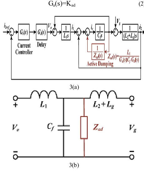
To better understand the illustrated active damping, Fig.2 has been redrawn as Fig.3 (a), which in circuit notation represents an impedance Zad (s) appearing across the filter capacitor Cf. This
notation has been drawn in Fig.3(b), which for the proportional
Ga (s) expressed in (2) leads to the resistive damper shown in
Fig.3 (c), if delays are ignored (Zad (s) = Rad)
Gd(s) =e-1.5Tss (1)
Fig.2. Per-phase diagram of grid current control loop with external capacitor–current active damping.
G
a(s)=K
ad (2)3(a)
3 (c)
Fig. 3. Equivalent representation of capacitor–current active damping.
(a) Block diagram representation. (b) Equivalent circuit with delays considered. (c) Equivalent circuit of proportional
controller without considering delays.
With delays included, impedance Zad (s) cannot be simplified,
and is represented by (3)
Zad(jɷ)=
(3)
The imaginary term in (3) can, in principle, cause the LCL resonance frequency to vary, while it’s real term can become negative if the LCL resonance frequency is located between fs/6 and the Nyquist frequency fs/2. The latter implies
an ineffective active damping with the nonminimum phase grid current behavior expected, owing to the presence of open-loop RHP poles. Proportional active damping expressed in (2) is therefore not a robust solution, as compared to the proposed RC damper to be discussed in the following.
III PROPOSED VIRTUAL RC DAMPER
A. Basic Princip le
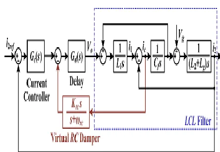
Fig.4 shows the proposed active RC damper, which unlike (2) has an additional first-order high-pass filter included. The resulting transfer function can thus be expressed as (4), where Krc and ωrc represent its gain and cutoff frequency,
respectively.
G
a(s)=
(4)Fig.4 Block diagram of proposed virtual RC damper. Corresponding equivalent circuits representing the proposed scheme can also be drawn as in Fig.5, where a virtual series RC damper can clearly be seen if delays are ignored. Expressions for the damper without considering delays can specifically be derived as (5)
Rrc= Crc= ɷrc=
(5)
Unlike (3) for proportional capacitor–current feedback, the real and imaginary terms of (6) include a second expression, which can be tuned by Crc. This is helpful since the
likelihood of Re {Zrc} being negative can now be lessened by
tuning.
Fig.5. Equivalent circuit of proposed virtual RC damper: (a) with and(b) Without delays considered.
These expressions change to (6) after incorporating delays
Z
rc(j
ɷ
)=
(1-j )[cos(1.5
ɷ
T
s)+jsin(1.5
ɷ
T
s)]
Re{Zr
c(j
ɷ
)}=R
rccos(1.5
ɷ
T
s)
+sin(1.5
ɷ
T
s)
Im{Zr
c(j
ɷ
)}=R
rccos(1.5
ɷ
T
s)
+sin(1.5
ɷ
T
s)
B. Robus t ness Evaluat ion and P aramet er T uning For evaluating robustness subject to a wide grid inductance variation, z-domain root locus analysis is performed on the scheme shown in Fig.4. Two transfer functions of the “plant” (converter and LCL filter) are necessary, and are hence derived accordingly. The first is obtained by applying zero-order hold (ZOH) discretization to Gvc (s) in (7) for relating the
converter output voltage and filter capacitor current. The second is obtained by applying impulse invariant transformation to Gcg
(s) in (7) for relating the filter capacitor current and grid current [23]. The resulting transfer functions obtained are given in (8) and (9), where ωres represents the LCL resonance frequency
Gvc(s) = =
Gcg(s) = = (7)
Gvc(z) =
(8)
Gcg(z) = (9)
The high-pass filter used for the virtual RC damper can next be discretized by Tustin transformation, which is expressed Combining (8) to (10), Fig. 7 shows the closed-loop pole trajectory of grid current control scheme, where Gc(s) in Fig.4 is
assumed to be a simple proportional gain designed with (L1+L2)
considered and for a PM of 45°[19].
The pole movement caused by the high-pass filter gain Krc is
plotted when its cutoff frequency ωrc is swept from 0 to 2ωs with
a step of 0.2ωs. In total, three grid inductance values are
evaluated with the LCL filter parameters listed in Table 1, which give three resonance frequencies centered around the critical frequency of fs/6=1.67kHz.
C. Frequency -Domain Comp arison
To further strengthen attractiveness of the proposed virtual RC damper, comparison among the three representative cases is performed in the frequency-domain. As mentioned in, Gc(s) in Fig.2 for all three cases have been simplified to a proportional gain designed with (L1+L2) and a PM of 45°
considered [19]. Beginning with the first case having no external active damping (Ga(s) = 0 in Fig.2). The plots clearly show a
reduction of LCL resonance frequency as the grid inductance increases, which will eventually lead to instability when the resonance frequency falls below fs/6.
D. Sy nchronous -Frame Imp lement at ion
The virtual RC damper in (3.4) can equivalently be realized in the synchronous frame after applying the necessary frequency shifting transformation according to the first
expression in (11) [6], [8]. Transfer function of the resulting RC damper in the synchronous frame is thus given by the second expression in (11), whose implementation involves cross-coupling, and is hence more complex like shown in Fig.11. Realizing and analyzing the damper in the stationary frame is thus generally recommended because of simplicity
Gdq(s)=Gαβ(s+jɷ1) (10)
Ga-dq(s)= Krc (11)
IV SELECTIVE HA RM ONIC COMPENSATION
Selective harmonic compensation is performed by placing resonant peaks at frequencies identified for compensation. It can be performed in the synchronous or stationary frame. For the latter, multiple resonant controllers are commonly used, which for L-filtered converters, have been proved to compensate for harmonics up to the Nyquist frequency [9]–[11], after introducing the necessary discretization and phase compensation. The resulting discretized resonant controllers are described next, before discussing how their harmonic compensation frequency range should be chosen for LCL-filtered converters.
A. Discret iz ed Resonant Cont rollers
Fig.12 shows two discretized resonant controllers used for selective harmonic compensation. In common, they consist of a forward Euler and a backward Euler integrator, which for the basic structure shown in Fig.12 (a), can be expressed as (12), where Kih is the resonant gain, θh is the compensation phase
lead, h is the harmonic order, and ω1 is the grid angular
GRh (z)=K1hTs
(
12)
Fig.6. Block diagram of proposed virtual RC damper in the synchronous frame.
Fig.7 (a) Basic block diagram
Equation (12) is, in fact, an approximation of the more precise resonant controller expressed in (13) [10]. The approximation helps to speed up computation, but is generally less accurate because of a reorientation of resonant poles and zeros from their intended positions. This discrepancy leads to frequency errors of the resonant peaks, which will further exacerbate as Tsand hω1
increase [11]
GRh (z)=K1hTs (13)
Fig.12 (b) therefore shows an improved resonant controller [8] with two added features for gaining better accuracy. The first is to replace cos (hω1Ts) in the denominator of (13) with a higher
sixth-order Taylor series to strengthen the resonant pole accuracy. The second is to modify the phase lead input θh so that
more accurate zeros can be obtained. The improved resonant controller generally functions well with an L-filtered converter, determination of θh for an LCL-filtered converter is however not straightforward because of possible phase change around the LCL resonance frequency. This is further complicated by the non minimum phase behavior of the proportional capacitor– current damper, which in principle will restrict the compensation of higher harmonic frequency.
Fig.7 (b) improved discretized resonant controllers with two integrators.
Fortunately, the non minimum phase behavior can be removed by the proposed virtual RC damper, where the frequency range for harmonic compensation can hence be extended. The next Subsection is thus used to identify this range, within which θh can be determined easily for harmonic
compensation.
B. Effect ive Comp ensat ion Range
Consequently, the harmonic compensation range chosen must be reduced significantly, if the traditional guideline of designing resonant controllers below the gain crossover frequency is followed. More correctly, resonant controllers should be able to compensate well as long as their frequencies are below the LCL resonance, at which a rapid transition in phase occurs. The resonance frequency is therefore the true upper limit, below which, the phase lead θh needed for each
resonant controller can be approximated as [8]
= (14)
In terms of harmonic compensation stability, it is therefore important to keep ωrc low. This is however in contrast, where a higher ωrc is recommended for a better damping robustness even when the grid inductance Lg varies widely. A compromised
range might hence be 0.2ωs ≤ ωrc<0.5ωs, where the upper limit
denotes the Nyquist angular frequency. Generally, the Nyquist frequency should not be exceeded because of possible noise amplification associated with the high-pass filter when in a noisy environment or sampling effects found in a digitally controlled system. It is thus a critical limit that should preferably be observed in practice, even though not strictly necessary.
V. Sp ace Vector Puls e W id th M o d u latio n (SVPW M )
Space Vector Modulation (SVM) was originally developed as vector approach to Pulse Width Modulation (PWM) for
modulation technique is to obtain variable output having a maximum fundamental component with minimum harmonics. Space Vector PWM (SVPWM) method is an advanced; computation intensive PWM method and possibly the best techniques for variable frequency drive application.This PWM technique approximate the reference voltage by a combination of eight switching pattern and treats the sinusoidal voltage as a constant amplitude vector rotating at constant frequency.
There are various variations of SVM that results in different quality and computational requirments.one major benifit is in the reduction of total harmonic distortion created by rapid swithching inherent to this PWM algorithm.
VI. M A TLAB/SIMULATION RESULTS
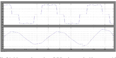
The measured PCC voltage and grid current for one phase of the LCL-filtered converter with no active damping is shown in the figures with different values of inductance . As the grid inductance Lg increases from , the converter obviously becomes unstable as the LCL resonance frequency moves below the critical value of fs/6=1.67 kHz.
Fig 8.Matlab/Simulink diagram of PCC voltage and grid current without external active damping
Fig.9. Simulink result of Measured per phase PCC voltage and grid current without external active damping with Lg=0mH
Fig.10 Measured PCC voltage THD without external damping with lg=0mH
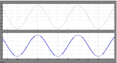
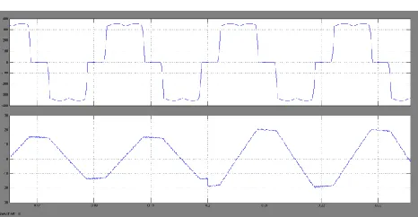
Fig.11. Simulink result of Measured per phase PCC voltage and grid current without external active damping with Lg=4.5mH
Fig.13.Simulink result of Measured per phase PCC voltage and grid current without external active damping with Lg=9mH
Fig.14. Measured PCC voltage THD without external active damping with Lg=9mH
The measured PCC voltage and grid current for one phase of LCL –filtered converter with conventional propotional capacitor –current active damping is shown in the figures from 16-18 for differentinductance values.The step response of the grid current is not effectively damped with visible oscillatory ripple noted.The oscillatory response is more prominant in fig 17 ,because with Lg=4.5mH ,its LCL resonance frequency is closest to ystem resonant frequency,above this frequency negative virtual resistance added unintentionally to destabilize the converter.
Fig.15. Matlab/Simulink diagram of PCC voltage and grid current with conventional proportional capacitor–current active
damping.
Fig16. Simulink result of Measured per phase PCC voltage and grid current of conventional capacitor-current active damping
with Lg=0mH
Fig.17Simulink result of Measured per phase PCC voltage and grid current of conventional capacitor-current active
damping with Lg=4.5mH
Fig 18 Simulink Result of Measured per phase PCC voltage and grid current of conventional proportional capacitor–current
active damping with Lg = 9 mH.
Fig. 19 Matlab/Simulink diagram of PCC voltage and grid current with proposed virtual RC damper.
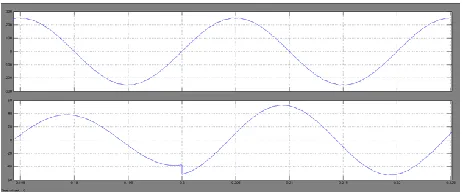
Fig.20 Measured per phase PCC voltage and grid current of proposed virtual RC damper with Lg = 0 mH.
Fig.21 Measured per phase PCC voltage and grid current of proposed virtual RC damper with Lg = 4.5 mH
Fig. 22 Measured per phase PCC voltage and grid current of proposed virtual RC damper with Lg = 9 mH.
For evaluating harmonic mitigation,a square PCC voltage with sizable low order harmonics was created by the power supply.With an improperly controlled converter,its injected grid current is usually be nonsinusoidal with significantly lower order harmonics anticipated.These lower order harmonics however be eliminated by selective harmonic compensation to obtain a sinusoidal grid current even with the square PCC voltage.
Resonant controllers for different grid inductances are thus placed to the highest of the resonant harmonic.These highest resonance terms are very close to the LCL resonace frequencies.
Fig.23 Matlab/Simulink diagram of Measured per p hase PCC voltage and grid current with low cut off frequency for t he
virt ual RC damp er
Fig.24 .Measured per phase PCC voltage and grid current with low cutoff frequency for the virtual RC damper (ωrc = 0.2 ωs )
with Lg=0mH
Fig.25 Measured per phase PCC voltage and grid current with low cutoff frequency for the virtual RC damper
Fig. 26 measured per phase PCC voltage and grid current wit h low cutoff frequency for the virtual RC damper (ωrc = 0.2 ωs ).
Wit h Lg = 9 mH
Measured per phase PCC voltage and grid current with high cutoff frequency is shown in the figure 27.The more oscillatory response is caused by the phase lag effect due to high cutoff frequency.so it is appropriate to choose ωrc within the
range of 0.2 ωs
≤
ωrc≤0.5 ωs to ensure effective harmoniccompensation up to the LCL resonance frequency,while preserving robustness even when Lg varies.
Fig.27 Matlab/Simulink Circuit for Measured per p hase PCC voltage and grid current with high cut off frequency for t he
virt ual RC damp er.
Fig.28 Measured per phase PCC voltage and grid current wit h high cutoff frequency for the virtual RC damp er(ωrc = 3 ωs)
wit h L9=0mH
Fig 29 Measured per phase PCC voltage and grid current wit h high cutoff frequency for the virtual RC damper (ωrc = 3 ωs)
wit h L9=4.5mH
Fig.31 Simulink result of measured per phase PCC voltage and grid current with high cutoff frequency for t he virt ual RC
damp er (ωrc = 3 ωs ) wit h Lg = 9 mH .
VII.CONCLUSION
REFERENCES
[1] Keng-Yuan Chen, Jwu-Sheng Hu, and Jau-Nan Lin,“Voltage
Source Inverter Drive Using Error-compensated PulseWidth Modulation,”Journal of Power Electronics, Vol.
16, No. 1, pp. 388-397, January 2016.
[2] Keng-Yuan Chen and Jwu-Sheng Hu, “A Filtered SVPWM for Multiphase Voltage Source Inverters Considering Finite Pulse-Width Resolution,”IEEE Transactions On Power Electronics, Vol. 27, No. 7, July 2012.
[3] E.AnandhaBanu, Dr.D. ShaliniPunithavathani, “Selective Harmonic Elimination In UPS – A Survey,”International Journal of Scientific & Engineering Research, Volume 5, Issue 4, April-2014 ISSN 2229-5518.
[4] Ashish Gupta, Sanjiv Kumar, “Analysis of Three Phase Space Vector PWM Voltage Source Inverter for ASD’s,” IJETAE ISSN 2250-2459, Volume 2, Issue 10, October 2012 [5] X. Wang, F. Blaabjerg, and Z. Chen, “Synthesis of variable harmonic impedance in inverter-interfaced distributed generation unit for harmonic damping throughout
distribution network,” IEEE Trans. Ind. Appl., vol. 48, no. 4, pp. 1407–1417, Jul./Aug. 2012.
[6] P.Mattavelli, “A closed-loop selective harmonic compensation for active filters,” IEEE Trans. Ind. Appl., vol. 37, no. 1, pp. 81–89, Jan./Feb. 2002.
[7] A. Yepes, F. Freijedo, J. Gandoy, O. Lopez, J. Malvar, and P. Comesana, “Effects of discretization methods on the performance of resonant controllers,” IEEE Trans. Power Electron., vol. 25, no. 7, pp. 1692–1712, Jul. 2010. [8] F. Wang, J. L. Duarte, M. A. M. Hendrix, and P. F. Ribeiro,
“Modeling and analysis of grid harmonic distortion impact of aggregated DG inverters,” IEEE Trans. Power Electron., vol. 26, no. 3, pp. 786–797, Mar. 2011.
[9] R. Venturini, P. Mattavelli, P. Zanchetta, M. Sumner, “Adaptive selective compensation for variable frequency active power filters in more electrical aircraft,” IEEE Trans. Aero.Electron. Syst., vol. 48, no. 2, pp. 1319–1328, Apr. 2012.
[10] J. Dannehl, M. Liserre, and F. W. Fuchs, “Filter-based active damping of voltage source converters with LCL filter,” IEEE Trans. Ind. Electron., vol. 58, no. 8, pp. 3623– 3633, Aug. 2011.
[11] Yepes, F. Freijedo, O. Lopez, and J. Gandoy, “High-performance digital resonant controllers implemented with two integrators,” IEEE Trans. Power Electron., vol. 26, no. 2, pp. 563–576, Feb. 2011.
[12] M.liserre,F.Blaabjerg, and S.hansen,”Design and control of an lcl-filter-based three –phase active rectifiers,”IEEE Trans,ind.appl.,vol.41,no.5,pp.1281-1291,sep/0ct.2005 [13] E.Twinning and D.G.Holmes,”Grid Current regulation of a
three phase voltage source inverter with an LCL input filter”,IEEE Trans.power Electron.,vol.18,no.3,pp.888-895,may 2003.
[14] R.N beres ,X.wang ,F.Blaabjerg,C,L,Bak,and M.Liserre,” A review of passive filters for grid-connected voltage source converters” in proc, IEEE Appl.power Electron .conf.Expo.,2014,pp 2208 -2215
[15] J.Dannel,M.Liserre ,and F.W fuchs. “Filter Based active damping of voltage source converters with LCL filter”, IEEE Tran,ind, electron., vol.58,no 8,pp. 3623-3633
Authors:
Ms. Ch.Nandini doing M.Tech in PE specialization in Teegala Krishna Reddy Engineering college, area of interests are power systems and power electronics.
Mr. Madhu Babu Thiruveedula completed M.Tech in IPA specialization. Currently working as Assistant Professor in Teegala Krishna Reddy Engineering college, area of interests are power electronics, power systems and electrical machines.