Reduced-Rank Chip-Level MMSE Equalization for the 3G
CDMA Forward Link with Code-Multiplexed Pilot
Samina Chowdhury
School of Electrical Engineering, Purdue University, West Lafayette, IN 47907-1285, USA Email: [email protected]
Michael D. Zoltowski
School of Electrical Engineering, Purdue University, West Lafayette, IN 47907-1285, USA Email: [email protected]
J. Scott Goldstein
SAIC 4001 N. Fairfax Drive, Suite 400, Arlington, VA 22203, USA Email: [email protected]
Received 31 July 2001 and in revised form 15 March 2002
This paper deals with synchronous direct-sequence code-division multiple access (CDMA) transmission using orthogonal channel codes in frequency selective multipath, motivated by the forward link in 3G CDMA systems. The chip-level minimum mean square error (MMSE) estimate of the (multiuser) synchronous sum signal transmitted by the base, followed by a correlate and sum, has been shown to perform very well in saturated systems compared to a Rake receiver. In this paper, we present the reduced-rank, chip-level MMSE estimation based on the multistage nested Wiener filter (MSNWF). We show that, for the case of a known channel, only a small number of stages of the MSNWF is needed to achieve near full-rank MSE performance over a practical single-to-noise ratio (SNR) range. This holds true even for an edge-of-cell scenario, where two base stations are contributing near equal-power signals, as well as for the single base station case. We then utilize the code-multiplexed pilot channel to train the MSNWF coefficients and show that adaptive MSNWF operating in a very low rank subspace performs slightly better than full-rank recursive least square (RLS) and significantly better than least mean square (LMS). An important advantage of the MSNWF is that it can be implemented in a lattice structure, which involves significantly less computation than RLS. We also present structured MMSE equalizers that exploit the estimate of the multipath arrival times and the underlying channel structure to project the data vector onto a much lower dimensional subspace. Specifically, due to the sparseness of high-speed CDMA multipath channels, the channel vector lies in the subspace spanned by a small number of columns of the pulse shaping filter convolution matrix. We demonstrate that the performance of these structured low-rank equalizers is much superior to unstructured equalizers in terms of convergence speed and error rates.
Keywords and phrases:CDMA forward link, minimum mean square error equalization, pilot code.
1. INTRODUCTION
Mobile units in current code-division multiple access (CDMA) cellular systems use a Rake receiver, which is a
maximal-ratio combiner and can be interpreted as a bank
of filters matched to the channel that combine the energy from multiple paths [1]. The Rake filter is the optimum (maximum likelihood) demodulator when there is no in-terference from other users [1]. In IS-95 and the proposed third-generation (3G) systems, orthogonal Walsh-Hadamard codes are used to spread the different users’ data symbols on the forward link. At the downlink receiver, after removing the coherent carrier, the signal is multiplied by the synchronized
base station long code and then decorrelated with the desired user’s spreading code. In a flat fading environment, this will ensure that any interference due to other users in the same cell is eliminated.
regardless of whether the fading is flat or not. In such en-vironments, the Rake receiver is suboptimal, because it herently treats MAI as uncorrelated noise. The multipath in-duced MAI also necessitates very tight power control. When many or all users are active in the cell, the bit error rate (BER) curve of the standard Rake receiver flattens out at higher signal-to-noise ratio (SNR) [2]. Thus, in situations where the number of active users approaches the spreading gain, the Rake receiver does not provide adequate performance.
The maximum likelihood multiuser detector was derived in [3] for the general case, and was shown to have com-putational complexity that increases exponentially with the number of users. This makes the optimal receiver practi-cally infeasible. Recently, chip-level downlink equalizers have been proposed to significantly increase the capacity of 3G CDMA based high-speed wireless communication links. In the CDMA downlink, for a given user, the signals from all users in the same cell propagate through the same multi-path channel, so the multiple-access and interchip interfer-ence can be suppressed by linear channel equalization at the chip-level [4]. One advantage of chip-level equalization is that the equalizer coefficients depend only on the down-link multipath channel. In contrast, due to the base station dependent pseudorandom scrambling code, the optimum symbol-level equalizer varies from symbol to symbol, regard-less of whether the multipath channel changes or not. Also, the chip-level equalizer is valid for all users, as the coeffi -cients do not depend on the channel short code [5]. Down-link equalization prior to despreading to restore the orthog-onality of the different users’ signals and hence suppress MAI has been suggested in [2, 4, 5, 6, 7, 8, 9]. Of these, linear zero-forcing (ZF) and minimum mean square error (MMSE) equalizers (proposed by Ghauri and Slock [7] and indepen-dently by Krauss et al. [2] and Zoltowski and Krauss [9]) em-phasized the multichannel aspect by means of oversampling and/or multiple antennas at the mobile station.
Given a perfect estimate of the common downlink chan-nel, zero-forcing equalization is possible in the noiseless case, regardless of the number of users, provided that sufficient spatio-temporal diversity is available [7]. But in the practical situation of noise in the received signal, the ZF equalizer may suffer from significant noise enhancement. In [2], the sum of the chip sequences from all the users is modeled as an i.i.d. random sequence, resulting in a “simple” chip-level equal-izer that does not depend on the (Walsh-Hadamard) channel code, or the base station dependent long code. The equalizer is followed by correlation with the desired user’s spreading code and the output, downsampled by the spreading factor, gives the symbol estimate. The resulting chip-level MMSE es-timators with perfect channel estimation were shown to out-perform both ZF and Rake [2].
References [2, 4, 5, 6, 7, 8, 9] all assumed that the chan-nel statistics and noise power are known at the receiver, hence the performances presented therein represent “upper-bounds” achievable with perfect channel estimation. A blind linear equalization algorithm which equalizes for the com-mon downlink channel was proposed in [10], based on max-imizing signal-to-interference plus noise ratio (SINR).
Sev-eral adaptive versions of chip-level equalizers have been pro-posed, such as in [11, 12, 13]. In [11], the matched filter for the chip sequence was followed by an adaptive chip decorre-lator based on blind linear decorrelation. In [12], the Grif-fith algorithm was used to update the multiuser chip esti-mator. However, both receivers were assumed to have perfect channel knowledge. A channel-response minimum-output energy equalizer was proposed in [14], which outperforms Rake for large number of users, provided that the channel es-timation error is not significant. Adaptive equalization which requires no knowledge of the channel or the other users’ codes was proposed by Frank and Visotsky in [5], where they assumed synchronization with the base station long code and suggested training at chip-level using the code-multiplexed common pilot channel as reference, but no simulation re-sults were presented. This straightforward adaptation does not exploit the orthogonality of the channel codes, and can-not suppress the intracell users due to pseudorandomness of the long code. Hence the SNR in the adaptation is low and the pilot-chip trained equalizer performs as poorly as Rake except at high SNR [13].
For high data rate applications, the multipath delay spread may span numerous chips so that the MMSE equalizer requires computation of a large number of coefficients, and may thus take an unacceptably long time to converge in adap-tive implementations. As a result, application of reduced-rank filtering methods in the context of equalization in CDMA has been an active topic of research in recent years. Goldstein et al. [15, 16, 17] first formulated the multistage nested reduced-rank technique for approximating the classi-cal Wiener filter. Their approach uses information from both the covariance matrix and the cross-correlation vector to de-termine the basis of a lower-dimension subspace that the Wiener filter is constrained to lie within. This method does not require any knowledge of the eigenvectors of the chan-nel covariance matrix, and so involves much less computa-tion than either the principal components (PC) [18] or the cross-spectral components (CS) [19] methods, the two most widely known reduced-rank techniques. A similar approach was developed in [20, 21, 22] where they used an orthonor-mal auxiliary vector (AV) in conjunction with the matched filter (Rake) to maximize the SINR subject to constraints.
The authors of [23, 24], applied adaptive multistage nested Wiener filter (MSNWF) to the reverse link with asyn-chronous users, flat fading, and no long code. An important result from their analysis is that the rankDneeded to achieve a desired SINR does not scale with system size. Indeed, through extensive supporting simulations, the MSNWF was shown to achieve near optimal SINR performance with a subspace of dimension roughly equal toD=8 or less where the full-rank space was of dimension 128. Another known application of the MSNWF is the cancellation of narrowband and wideband jammers for global positioning system (GPS) employing a power minimization based space-time prepro-cessor [25, 26].
of reduced-rank MMSE equalization for the CDMA down-link. We show that, with perfect knowledge of the chan-nel statistics, the MSNWF requires only a small number of stages to achieve near full-rank MMSE performance over a wide range of SNR. We then use a training-based block adaptive algorithm whereby the filter coefficients are adapted
on the symbol-levelusing the code-multiplexed pilot channel
that carries known symbols, to analyze the performance of the MSNWF when the channel is unknown. The SINR plot shows a convergence speed comparable to full-rank recursive lease square (RLS) and much faster than full-rank least mean square (LMS). Simulated bit error rate curves further illus-trate the excellent performance of the MSNWF.
We also present a reduced-rank MMSE equalizer that ex-ploits the structure and sparseness of the multipath chan-nel under high-speed, wideband conditions. In this case, the channel coefficients lie approximately in a subspace associ-ated with only a few columns of the pulse shaping filter con-volution matrix. We project the full-rank chip-level MMSE equalizer onto this much lower-rank subspace and illustrate a much better convergence rate than that achieved with an unstructured MMSE equalizer of similar rank.
The results in this paper are for the CDMA forward link with synchronous users, saturated loading, frequency selec-tive fading, long code scrambling and employing two an-tennas at the mobile receiver. The channel is assumed to be unvarying with time, which is generally true over a short time interval. We also assume that synchronization with the base station long code has been achieved. The rest of the paper is organized as follows. After describing the channel and data models in Section 2, Section 3 derives the chip-level MMSE estimator. Reduced-rank filtering based on the MSNWF is discussed in Section 4, and simulation results ob-tained for the CDMA downlink is presented in Section 5. Adaptive equalization based on the MSNWF is described in Section 6 along with simulation results. We present the new structured equalizer based on sparse multipath channel in Section 7 and corresponding simulation results in Section 8. Our conclusions are drawn in Section 9.
2. DATA AND CHANNEL MODEL
The channel model is shown in Figure 1. If the transmission is from only one base station, the impulse response for theith antenna channel between the transmitter and receiver (mo-bile station) is given by
hi(t)= Nm−1
k=0
hci[k]prc
t−τk
, i=1,2, (1)
where hci[k] is the time-invariant complex gain associated with thekth multipath at theith antenna; prc(t) is the
com-posite chip waveform (including the matched low-pass filters on the transmit and receive end). The chip waveform is as-sumed to have a raised cosine spectrum. AndNmis the total
number of delayed paths, that is, multipath arrivals, some of which may have zero or negligible power, so that the channel impulse response is sparse.
The transmitted “sum” signal may be described as
s[n]=cbs[n] Nu
j=1 Ns−1
m=0 bj[m]cj
n−Ncm
, (2)
wherecbs[n] is the base station dependent long code,bj[m] is
the bit/symbol sequence of thejth user,cj[n] is thejth user’s
channel (short) code of length Nc,Nuis the total number
of active users,Nsis the number of bit/symbols transmitted
during a given time window.
The signal received at theith antenna (after convolving with a matched filter having a square-root raised cosine im-pulse response) is given by
xi(t)=
n s[n]hi
t−nTc
+ηi(t), i=1,2, (3)
whereTcis the duration of one chip andηi(t) is a noise
pro-cess assumed white and Gaussian prior to coloration by the receiver chip-pulse matched filter.
2.1. Edge of cell/soft handoff
We consider the interference problem when the desired user is at the edge of a cell so that the total received signal at the mobile station is the sum of the contributions from two base stations, plus noise
xi(t)=xi(1)(t) +x (2)
i (t) +ηi(t), i=1,2 antennas at receiver,
(4)
where x(il)(t) denotes the signal received at theith antenna
due to transmission from thelth base station, andxi(t)
de-notes the total received signal at theith antenna.
At each antenna, we oversample the signalxi(t) to obtain r1i[n]=xi(nTc) andr2i[n]=xi(Tc/2 +nTc).
In thesoft handoff mode, the desired user’s data is trans-mitted simultaneously from the two base stations. At the re-ceiver, two equalizers are designed, one for each base station. The output of each of the two chip-level equalizers is related with the desired user’s channel code times the cor-responding base station’s long code. These two symbol es-timates are averaged to get the symbol estimate for the soft handoffmode. The block-diagram for the chip-level MMSE equalizer employing soft handoffis shown in Figure 2. In the
normal mode, the second base station is treated as
interfer-ence.
3. CHIP-LEVEL MMSE ESTIMATOR
The chip-level MMSE equalizer is designed to minimize the MSE between the multiuser synchronous sum signal, s[n], and the sum of the equalizer outputs, as depicted in Figures 1 and 2. Given the orthogonality of the channel codes, an estimate of the symbol, ˆbj[m], can be obtained via a correlate
and sum withcjandcbsat the output of the chip-level MMSE
equalizer.
Symbol
Figure1: Chip-level MMSE equalization for CDMA downlink with one base station.
Symbol
Figure2: Chip-level MMSE equalization for CDMA downlink, two base stations, soft handoff.
x[n]=H(1)s(1)[n] +H(2)s(2)[n] +η[n]
=Hs[n] +η[n], (5)
where H(l) is the 2N
g ×(L+Ng −1) channel convolution
matrix (Ng is the length of the equalizer, andLis the length
of the channel in chips.), comprised of
H(l)=
H is the composite channel convolution matrix H = [H(1) H(2)]. Ands(l)[n] is an (L+N
g−1) vector of the
trans-mitted signal, with the superscript denoting the correspond-ing base station.
The corresponding formulae for only one transmitting
base station can be found by simply removing the term in-volvingH(2)from (5).
Krauss et al. [2] made some simplifying assumptions to derive a chip-level MMSE equalizer that can be easily im-plemented. The sequence values for the multiuser sum sig-nal are assumed to be i.i.d. random variables. Otherwise, the covariance matrix of the sum signal s[n] is a compli-cated expression involving the Walsh-Hadamard spreading codes that vary from index to index. The i.i.d. assumption is valid if the (long) scrambling code is viewed as a random i.i.d. sequence and/or all users are active with equal power. With this assumption, the covariance matrix of the signal is
E{s[n]Hs[n]} = σ2
sI, and the MMSE equalizer was shown
to be 1)th position,Dcis the combined delay of the equalizer and
channel,σ2
s is the signal power, andRηη = E[ηH[n]η[n]].
In [2] and Section 5 of this paper, the delay Dc, 0 ≤ Dc ≤
(Ng+L−2), that yields the smallest MMSE is calculated
us-ing the actual channel statistics and that Dc is used in the
simulations.
Equation (8) has the form of the well-known Wiener-Hopf solution,
0
w1 1
w2 2
wN−2 N−2
wN−1
dN−2
BN−2
pN−2
xN−3
B2
x2
p2
x1
B1
p1
x0
Analysis filter bank Synthesis filter bank
d0
d1
d2
xN−2=dN−1=N−1
Figure3: Structure of successive stages of the multistage nested Weiner filter.
where Rxx is the channel covariance matrix and rdx is the
cross-correlation vector.
In [2, 27], the authors showed that the MMSE signifi-cantly outperforms the Rake receiver, especially when a large number of channel codes are active relative to the spreading factor. The difference is more pronounced when soft handoff is unavailable.
4. REDUCED RANK FILTERING
In general, the length of an MMSE equalizer should be at least equal to the channel length to achieve the desired per-formance, and longer equalizers yield better error rates [28]. Hence equalizers in the high-speed CDMA downlink will by necessity span many chips in length with a corresponding large number of degrees of freedom. In order to reduce the number of filter coefficients to be estimated, the received sig-nal vector may be projected onto a lower dimensiosig-nal sub-space, and the Wiener filter given by (9) constrained to lie in this subspace. This increases the speed of convergence dramatically for adaptive methods, if the subspace is cho-sen properly. But the overall MMSE for the reduced-rank filter may be higher than the MMSE for the full-rank fil-ter. The most widely known reduced rank techniques in sig-nal processing are the principal components method [18] and the cross-spectral methods [19], both based on eigen-decomposition of the channel covariance matrix.
4.1. Multistage nested Wiener filter
Goldstein et al. [15, 16, 17] first formulated the MSNWF, which uses information from the channel covariance matrix,
Rxx, and cross-correlation vector,rdx, to determine the bases
of the lower-dimension that wis constrained to lie within. The structure of the MSNWF is depicted in Figure 3. At each stage, a rank-one basis is selected based on maximal correla-tion between the desired signal,d0, and the observed signal
x0[n]. The observed vector process is decomposed by a
se-quence of nested filtersp1,p2, . . . ,pD,whereDis the order of
the filter,
pk= E
xk−1d∗k−1
E
xk−1d∗k−1
, (10)
anddk=pHkxk−1.
• Initialization:
c1=rdx=E[x0d0∗], δ1=
rH dxrdx, • Forward recursion:
Fork=1,2, . . . N−1 Do (1) pk=ck/δk, (2) Bk=null(pk), (3) dk=pHkxk−1,
(4) xk=Bkxk−1,
(5) ck+1=E[xkd∗k], (6) δk+1=
cH k+1ck+1,
• End
xN−1=dN=N, • Backward recursion:
ξN=E[|xN−1|2],δN=E[xN−1d∗N−1],wN =δN/ξN, • Fork=N−1, . . . ,2,1 Do
(1) k=dk−wk+1k+1,
(2) ξk=σd2k−δ 2
k+1/ξk+1,
(3) wk=δk/ξk, • End
Algorithm1: Basic MSNWF algorithm.
The input process to the (k + 1)th stage is xk[n] =
Bkxk−1[n], whereBkis ablockingmatrix such thatBkpk=0.
The outputs of the various stages are linearly combined via the scalar weights,w1, w2, . . . , wD−1, chosen so that the
mean square error at each stage is minimized. If the decom-position is carried out for the fullNstages, then the multi-stage nested filter is exactly equivalent to the full-rank clas-sical Wiener filter [15]. The filter-bank structure whitens the error residue at each stage, and compresses the colored por-tion of the observed data subspace and hence, it is optimal in terms of reducing the MSE for a given rank. The MSNWF does not require any eigen decomposition or inversion of the covariance matrix, and so represents a significant reduction in complexity over the full-rank Wiener solution and other reduced-rank techniques. This is very important for practical implementations, particularly if the rank one decomposition can be stopped after a few stages. The basic algorithm, based on [15] is listed in Algorithm 1.
The filter can be
Figure4: MSNWF as a lattice filter.
each stage,dk[n] is the output of a lengthNfilter,
A notable feature is that the first filter is orthogonal to filters of all the following stages, that is,
cH
kc1=δk1, k=1,2, . . . , N, (12)
δkidenotes the Kronecker delta function, which is 1 fork= i, and 0 otherwise. However, the filtershk, k = 2,3, . . . , N,
are not mutually orthogonal in general. The operation of the analysis filter-bank can be combined into aD×Ntransfer matrix, given by
The orthogonal decomposition ensures that the reduced di-mensionD×Dcorrelation matrixTDRxxTHD is tridiagonal
[15].
Honig and Xiao [24] first proposed choosing a projec-tion matrix on to the subspace orthogonal topkas the
block-ing matrix at each stage, hence retainblock-ing the lengthNof the filter and the “observed signal”xk[n]. With this choice for
the blocking matrix, TD = [p1 p2 · · · pD] forms an
or-thonormal basis for the reduced dimension subspace. More-over,wis constrained to lie in the Krylov subspace spanned by{rdx,Rxxrdx,Rxx2 rdx, . . .RDxx−1rdx}[24]. In this case,
Joham and Zoltowski [29] proved that this choice of the blocking matrix, that is, Bk = I−pkpHk, is optimum
in terms of maximizing the correlation between the scalar signals dk[n] and dk−1[n] at each stage. They developed a
covariance-levelorder recursiveform of the MSNWF working within the Krylov subspace, in which the backwards recur-sion coefficients and hence the weight vector and the mean square error, may be updated at each stage via a simple re-cursion.
4.2. Lattice structure of the MSNWF
Theblocking matrixis a very useful concept to develop and
analyze the performance of the MSNWF, but in practice, there is no need to calculate or store theseN×Nmatrices. A new reduced-complexity implementation was presented by Ricks and Goldstein in [30] based on the following substitu-tion: at thekth stage
This leads to the “lattice-type” structure for a D-stage MSNWF, as shown in Figure 4. This architecture has the ben-efit of being modular and scalable for hardware implementa-tion, as well as being computationally more efficient than the structure depicted in Figure 3.
50 40 30 20
10 0
−10
Time in chips 0
0.1 0.2 0.3 0.4 0.5 0.6 0.7 0.8
N
o
rm
aliz
ed
mag
nitude
Antenna 1 Antenna 2
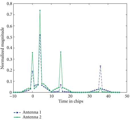
Figure5: Typical channel impulse response for simulated model.
and finds the “ideal” MSNWF solution after various stages, assuming thatRxx andrdxare known (perfect channel
esti-mation). The same simulations are also done for the edge of cell situation, when two base stations of equal power are re-ceived at the mobile-station and the receiver uses soft hand-off.
A wideband CDMA forward link was simulated similar to one of the options in the US CDMA2000 proposal. The chip rate was 3.6864 MHz (Tc=0.27µs), 3 times that of
IS-95. Simulations were performed for asaturated cell, that is, all possible 64-channel codes are active, and all users haveequal
power. The spreading factor wasNc=64 chips per bit. The
data symbols were BPSK, and spread with one of 64 Walsh-Hadamard codes. The signals were summed synchronously and then multiplied with a QPSK scrambling code of length 32678, similar to the IS-95 standard.
The channels were modeled to have four equal-power multipaths, uniformly distributed within a delay spread of 10 microseconds (corresponding to about 37 chips). The multipath coefficients are complex normal, independent ran-dom variables. The arrival times at antenna 1 and 2 are the same, but the multipath coefficients are independent. Figure 5 shows a typical channel’s impulse response with tails, sampled at the chip rate.
In the two-base station case, the maximum delay spread of the downlink channel from the second base station is also 10 microseconds, with 4 dominant multipaths arrivals at random. The channels are scaled so that the total energy from each of the two base stations is equal at the receiver. Specifically,
M
m=1 Ex(1)
m [n] 2
=
M
m=1 Ex(2)
m [n] 2
. (17)
SNR is defined to be the ratio of the sum of the average power of the received signals over all the channels, to the average
noise power, after chip-matched filtering. Since the spread-ing factor (number of chips per symbol) is equal to the num-ber of users, and each user contributes the same amount of power, this chip signal SNR is equal to the postcorrelation (or despread) SNR per user per symbol. The curves were gener-ated by averaging 100 or more different channels. Note that the abscissa in the graphs is the postcorrelation SNR foreach
user, which includes a processing gain of 10 log(64)≈18 dB. Figure 6 plots the mean square error for the different reduced-rank methods as a function of the subspace dimen-sion,D. The channel statistics and noise power are assumed to be known. In the single base station case, Figure 6a, the di-mension of the full space is 114 (the equalizer length is 57 at each of the 2 antennas, as multipath delay spread is 37 chips and the chip pulse waveform is cut offafter 5 chips at both ends). The MSE for MSNWF is seen to drop dramatically withD, and achieves the performance of the full-rank Wiener filter at dimension approximately 7! In contrast, the prin-cipal components method takes longer than twice the de-lay spread, and the cross-spectral method does only slightly better.
Figure 7a displays the BER curves obtained with the MSNWF for different sizes of the reduced-dimension sub-space. For comparison, the BER for a conventional Rake and full-rank chip-level MMSE equalizer are also shown. The channel statistics are assumed to be known perfectly, so these curves serve as an informative upper bound on the perfor-mance. It is observed that even a 2-stage reduced-rank filter outperforms the Rake at all SNRs and only a small number of stages of the MSNWF are needed in order to achieve near full-rank MMSE performance over a practical range of SNRs. Figures 6b and 7b display similar plots, but for the edge of cell scenario. In this case, there are 4 effective channels at the receiver, because we sampled the received signal at twice the chip-rate at each antenna. It can be shown that the two-polyphase channels created from either antenna are nearly linearly dependent in the case of a sparse multipath chan-nel as in our simulations. The dimension of the full space is 228, which makes the full rank calculations very cumber-some. Amazingly, the MSE for MSNWF still goes down very steeply with rank and achieves the full-rank value for sub-space dimension of only 8 or so. Compared to the PC and CS methods, this is a huge difference in effective rank reduc-tion. In the BER plots of Figure 7b, the bit error is calculated for the soft handoffmode. With perfect channel estimation, the MSNWF can achieve error rates similar to the full-rank MMSE over practical SNR range after stopping at stage as low as 5!
6. ADAPTIVE EQUALIZATION
120
Dimension of reduced-rank subspace forgc
−8
Multistage nested Wiener filter Principal components Cross-spectral components
(a) One base station.
250
Dimension of reduced rank subspace forgc
−6
Multistage nested Wiener filter Principal components Cross-spectral components
Normal handoff
(b) Two base stations.
Figure6: MSE versus rank of reduced dimension subspace, known channels, SNR=10 dB.
the knowledge of number of active users, all of the active channel codes and the transmitted symbols. Instead, we use the pilot channel of CDMA downlink, which has a known code and known symbols. For DS-CDMA with orthogonal spreading codes, the chip-level MMSE equalizer restores the synchronous sum signal transmitted by the base station, so the MMSE equalizer is identical for all channels within a multiplicative constant and the common pilot code can be used to train for any other channel code [5]. Our approach is to train offthe pilot symbols by using directly the following
20 Exact MMSE, rank 114
(a) One base station.
20
(b) Two base stations.
Figure7: BER for different chip-level equalizers for CDMA down-link, known channels.
relations (cf. Figure 1):
(ii) Despreading
Thus we convolve the received chip-sequence with the pilot channel code (which is all 1’s) times the appropriate portion of the base station scrambling code, and then train the equalizer on the pilot symbols. This is equivalent to first equalizing and then despreading due to the commutativity of convolution. We use ablock-adaptivetraining-based algo-rithm that implements the lattice-type MSNWF of Figure 4. The algorithm is given in Algorithm 2. We also find the full-rank Wiener solutions, using least mean squares and recur-sive least squares algorithms for purposes of comparison in the simulations.
First, we simulate the single base station scenario, where the dimension of the full-rank solution is 114 as described before. Figure 8 plots the output SINR for different chip-level equalizers versus time in symbols, at a fixed SNR. The out-put SINR is calculated using the formula derived by Krauss in [27]. The MSNWF after stages 5 and 10 yields very good performance with low sample-support. The convergence rate is similar to that of a full-rank RLS, which even asymptoti-cally, does not beat the MSNWF of rank only 10! The LMS algorithm converges much slower and to a lower SINR. For the two-base station case, we implement soft handoff. The asymptotic SINR is almost 3 dB lower for all the equalizers due to the added interference from the MAI of the second base station. But the convergence speed of low-rank MSNWF is still impressive.
Block size=Ntsymbols. • Initialization:
d0=bwherebis the lengthNtvector of the pilot symbols, andY0=[y[1], . . . ,y[Nt]],y[m]=CH1[m]˜x[m].
• Forward recursion: Fork=1,2, . . . , D, • Backward recursion:
D=dD,
Fork=D, D−1, . . . ,1 Do
wk=(kdHk−1)/k2=δk/k2, k−1=dk−1−wkk
Algorithm2: Structured lattice MSNWF algorithm for the CDMA forward link.
The output SINR is plotted versus the rank of the reduced dimension subspace, D, in Figure 9 at two different SNRs. For comparison, the SINR output for an “ideal” MSNWF, that is, with perfect channel estimation, is included. At a low SNR of 0 dB, the SINR after 200 symbols for the adaptive MSNWF shows a distinct peak at a dimension of only 3! At 10 dB SNR, the peak is less prominent, but the SINR output goes down after stage 8 or so. This can be explained as the “penalty” for learning the channels, that is, in the presence of significant noise, the lower rank MSNWF trades offa bias in the symbol estimate for a lower variance by working in a lower dimensional space so as to pass less noise. As the signal power increases, the higher-dimensional filters yield better approximation to the full-rank solution, as the lower rank filters do not have adequate degrees of freedom to suppress MAI and ISI.
The BER curves in Figure 10 illustrate the performance of these equalizers after training with 200 symbols in the sin-gle base station case, and 300 symbols in the multiple base stations case. At low SNRs, the BER for MSNWF stage 5 is actually slightly lower than the BER for stage 10 or 15, as ex-pected from the SINR graphs of Figure 9.
+ + +
+
+ +
+
+
+
+
+
500 400
300 200
100 0
Number of training symbols
−10
−5 0 5 10 15
SINR
(dB)
MSNWF, stage 5 MSNWF, stage 10
Full-rank LMS Full-rank RLS (a) One base station, SNR=10 dB.
+ +
+
+ +
+
+
+
+ +
+
+
+
+ o
o o
o o
o o
o o o
+ o
500 400
300 200
100 0
Number of training symbols
−10
−6
−2 2 6 10
SINR
(dB)
MSNWF, stage 5 MSNWF, stage 10
Full-rank LMS Full-rank RLS (b) Two base stations, SNR=10 dB, soft handoff.
Figure8: Output SINR versus time for adaptive chip-level equaliz-ers for CDMA downlink.
7. STRUCTURED EQUALIZER IN SPARSE MULTIPATH For high-speed CDMA, typically the vector of multipath channel coefficients is sparse, but the chip-rate linear equal-izers will not be sparse in general. Under certain conditions, the overall channel coefficients lie in a subspace associated with the pulse shaping filter convolution matrix. A semi-blind direct equalization approach that utilizes this structure to impose a penalty on nonblind equalizers was presented in [31], and compared to nonblind MMSE equalizers for indoor channels. For wideband CDMA, additional benefits
30 25
20 15 10 5
0
Dimension of reduced-rank subspace
−1 0 1 2 3 4 5 6
SINR
(dB)
Known channels Training with 200 symbols
(a) SNR=10 dB.
30 25 20 15 10
5 0
Dimension of reduced-rank subspace 2
4 6 8 10 12 14
SINR
(dB)
Known channels Training with 200 symbols
(b) SNR=10 dB.
Figure9: SINR of MSNWF versus dimension of reduced-rank sub-space, 1 base station.
may be obtained by realizing that, due to the sparse nature of the multipath arrivals, the total channel vector lies in a sub-space spanned by only a few columns of the pulse shaping convolution matrix [10]. If we project the full-rank chip-level MMSE equalizer onto this much lower-rank subspace, the equalizer should converge much faster.
It was shown in Section 3 that the channel cross-correlation vector is given by
20 15
10 5
0
SNR in dB 10−6
10−5 10−4 10−3 10−2 10−1 100
Av
er
ag
e
B
E
R
After 200 symbols training
MSNWF, stage 5 MSNWF, stage 10 MSNWF, stage 15
Full-rank LMS Full-rank RLS
(a) One base station.
20 15
10 5
0
SNR in dB 10−4
10−3 10−2 10−1
100 After 300 symbols training
MSNWF rank 5 MSNWF rank 10 MSNWF rank 15
Full-rank LMS Full-rank RLS
Soft handoff
(b) Two base stations.
Figure10: BER for adaptive chip-level equalizers for CDMA down-link.
If we restrict ourselves to the following two conditions:
(1) Ng ≥L, and
(2) Ng−1≥Dc≥L−1,
then it can be easily seen thatrdx now contains all the
ele-ments of the channel impulse response. In particular, if we chooseNg=LandDc=L−1, we get
rdx=
˜I ˜
I h1 h2
, ˜I=
0 · · · 1
. . .
1 · · · 0
. (22)
The impulse response for the channel between the trans-mitter and theith antenna at the receiver is given by (cf. (1))
hi(t)= Nm−1
k=0
hci[k]prc
t−τk
, i=1,2. (23)
If we sample at chip rate and assume a high enough chip rate so that the multipath delays are integer multiples of the chip periodTc(we will relax this assumption shortly), we can
write the channel vectors in (22) as
hi=Ghci, i=1,2, (24)
whereGis the convolution matrix corresponding to the chip pulse waveform, and hci is a sparse vector containing the multipath coefficients. In this case, the vector channelhilies
in a subspace spanned by only a few columns of Gand we can simplify (21) as
rdx=
Gp
Gp
hp1
hp2
=Ghp, (25)
whereGpcontains only theLccolumns of ˜IGcorresponding
to theLcdominant multipath arrivals, andhpis the vector
of corresponding complex gains, that is,hpconsists of only
nonzero elements ofhc.
Thus the chip-level MMSE equalizer has the form
gc=R−xx1rdx=R−xx1Ghp. (26)
This structure due to the sparse multipath channel can be utilized to increase the convergence speed of adaptive MMSE equalizers, if an estimate of the multipath arrival times τk, k =1, . . . , Lcis available at the receiver. We can then project
the observed data vector onto a rank 2Lc 2L subspace
by taking
yr[m]=GHR−xx1CHj[m]˜x[m]. (27)
This would also require estimation of the chip-level covari-ance matrix. We refer to the MMSE equalizer residing in this low-rank subspace as the “structured projected” equalizer, denoted bygr. Then the estimate of the desired user’s symbol
is given by
ˆ
bj[m]=gHryr[m]≡hˆHpyr[m]. (28)
7.1. Chip-level whitening with multistage nested Wiener filter
Direct inversion of Rxx in (27) can be avoided using the
500 400
300 200
100 0
Number of training symbols
−2 2 6 10 14
SINR
(dB)
Structured projected equalizer, rank 8
MSNWF solvesRxxγ[m]=y[m]
Rxxis 114×114
MSNWF, stage 5 MSNWF, stage 10 Exact inversion
Figure11: Application of MSNWF to covariance matrix inversion, SNR=10 dB.
Rxxγ[m]≈y[m]. (29)
Then ˆyr[m]=GHγ[m] is an approximation to the projected
data-vector.
The efficacy of the MSNWF is illustrated in Figure 11, which plots the output SINRs of 3 structured equalizers, the only difference is the use of 5 or 10 stages of the MSNWF to get approximate solution ˆyr[m] or direct inversion ofRxx
to obtain exact solution yr[m]. The dimension of Rxx is
114×114, so its inversion is prohibitively expensive, but only 10 stages of MSNWF is sufficient to give the same SINR over-all.
7.2. Generalized arrival times
When the multipath arrival times are not exact multiples of the chip period, (24) is only an approximate relation. In this case we form the basis vector matrix G(ν) by sampling the
chip-pulse shaping filter at rateTc/ν. The approximation
er-ror can be made arbitrarily small by increasingν.
The basis matrixGpis now formed by taking (ν+ 1)
con-secutive columns of ˜IG(ν)for each multipath arrival,
corre-sponding toντk/Tc , . . . , ντk/Tc. Maximum rank of
struc-tured projected equalizer is now 2Lc(ν+ 1). Note that our
scheme does not require any increase in the sampling rate of the received signal.
7.3. Delay estimation
The structured projected equalizer requires estimate of the multipath delays, but no knowledge of the multipath coeffi -cients is needed. The multipath delays will change relatively slowly as compared to the complex gains even in a time-varying situation. The use of multiple antennas at the re-ceiver enhances the quality of the delay estimates since the arrival times are the same at both antennas (the propagation
500 400
300 200
100 0
Time in symbols
−10
−5 0 5 10 15
SINR
(dB)
MSNWF, stage 8 MSNWF, stage 5 MSNWF, stage 2
(a) Structured projected equalizers.
500 400
300 200
100 0
Number of training symbols
−6
−2 2 6 10 14
SINR
(dB)
Structured projected
Unstructured, reduced-rank
MSNWF, stage 5 MSNWF, stage 8
(b) Comparison of structured projected and unstructured equalizers.
Figure 12: SINR convergence for chip-level equalizers using MSNWF, arrivals at exact chip-periods, SNR=10 dB.
500 400
300 200
100 0
Number of training symbols
−6
−2 2 6 10 14
SINR
(dB)
Full-rank LMS Full-rank RLS
Unstr. MSNWF, stage 8 Structured projected
Figure13: SINR versus time for different equalizers, arrivals at ex-act chip-periods, SNR=10 dB.
3 columns of ˜IGcentered on the doubtful estimate may be taken to formGp.
8. RESULTS
Figure 12a shows the output SINR vs. time (in symbols) at a fixed SNR of 10 dB for “structured projected” chip-level equalizers, for channels simulated as described in Section 5, that is, the arrival times are at exact multiples of the chip-period Tc. We assume that the receiver has already formed
estimates of the multipath arrival times. After the projection via (27), we use different stages of the MSNWF algorithm. The stage 2 MSNWF does not perform very well, but the con-vergence rate for stages 5 and 8 (maximum) is very good, as expected.
Figure 12b compares the SINR convergence speed of training-based unstructured chip-level equalizers and the structured projected equalizers, all of which use a MSNWF solution. It is clear that the structured projected equaliz-ers exploit the structure in the sparse channels to yield a much superior performance. The structured projected equal-izer is compared to full-rank RLS and LMS convergence in Figure 13. After training with 100 symbols there is approxi-mately 5 dB difference in output SINRs of the structured pro-jected MMSE equalizer and an unstructured MSNWF solu-tion of rank 10 and full-rank RLS.
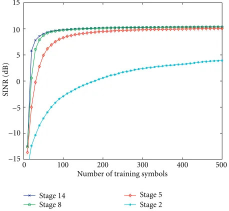
Next, we simulate frequency-selective channels where the first multipath arrival is at 0, and the other three are uni-formly distributed within 10µs, with the only constraint be-ing that the multipath delays are spaced at least one chip-period apart. Figure 14a shows the SINR plot after various stages of the MSNWF where the basis vectors are formed by sampling the pulse-shaping filter at rate Tc. In this case
the structured projected equalizers are of dimension 14, as
500 400
300 200
100 0
Number of training symbols
−15
−10
−5 0 5 10 15
SINR
(dB)
Stage 14 Stage 8
Stage 5 Stage 2 (a) Basis vectors formed by sampling atTc.
500 400
300 200
100 0
Number of training symbols
−15
−10
−5 0 5 10 15
SINR
(dB)
v=1, stage 8
v=2, stage 8
v=2, stage 20
v=4, stage 8
v=4, stage 32
(b) Basis vectors formed by sampling atTc/ν.
Figure 14: SINR convergence for chip-level equalizers using MSNWF, random arrivals, SNR=10 dB.
we form Gp by taking two consecutive columns of ˜IG
cor-responding to each multipath arrival that is in between two chip-periods. We see that 8 stages of the MSNWF are suf-ficient but there is a loss of about 2 dB in asymptotic SINR compared to Figure 12a due to the arrival times not being at exact chip periods.
Figure 14b shows the SINR plot where the basis vec-tors are formed by sampling the pulse-shaping filter at rate
20 15
10 5
0
SNR in dB 10−8
10−7 10−6 10−5 10−4 10−3 10−2 10−1 100
Av
er
ag
e
B
E
R
RAKE Full-rank LMS Full-rank RLS
Unstr. MSNWF, stage 10 Str. proj., rank 20
Figure15: Bit error rates graph, random arrival times.
recouped if we oversample by a factor of 2 and perform full-rank equalization (which is now full-rank 20). AtTc/4 the
conver-gence goes down due to the increased dimension of the filter (which is now 32) but there is no improvement in asymptotic SINR.
We plot the bit error rate graphs of the structured pro-jected equalizer where the pulse-shaping filter is sampled at rateTc/2, compare it with the full-rank RLS, and
reduced-rank unstructured equalizer curves in Figure 15. The multi-path delays are randomly distributed within 10µs. The struc-tured projected equalizer (of rank 20) exhibits significantly lower bit errors for all SNRs.
9. CONCLUSIONS
We presented reduced-rank chip-level MMSE equalizers for the CDMA downlink with frequency-selective multipath based on the multistage nested Wiener filter, for known channel case and also for training-based adaptation. The per-formance for the single base station case, and for the edge-of-cell scenario with soft handoffare very satisfactory. The con-vergence rate for MSNWF operating in a very low-rank sub-space was significantly better than LMS, and somewhat better than RLS. The BER performance showed improvement over the full-rank methods for practical SNR range. This excel-lent performance is achieved at a computational complexity in between LMS and RLS due to lattice-type structure that allows block-adaptive implementation through simple filter-ing operations.
We also developed a structured MMSE equalizer that uti-lizes the estimate of the multipath arrival times and sparse nature of the multipath channel to substantially reduce the number of parameters that need to be adapted. The con-vergence rate for this projected MMSE equalizer was
sig-nificantly better than unstructured MSNWF operating in a subspace of similar rank. The bit error rate performance of this structured MMSE equalizer was shown to be superior to full-rank RLS and reduced-rank unstructured MMSE equal-izer over a wide SNR range.
ACKNOWLEDGMENT
This research was supported by the Air Force Office of Sci-entific Research under grant No. F49620-00-1-0127 and by Texas Instruments’ DSP University Research Program.
REFERENCES
[1] J. G. Proakis, Digital Communications, McGraw-Hill, New York, NY, USA, 3rd edition, 1995.
[2] T. P. Krauss, M. D. Zoltowski, and G. Leus, “Simple MMSE equalizers for CDMA downlink to restore chip se-quence: comparison to zero-forcing and rake,” inProc. IEEE Int. Conf. Acoustics, Speech, Signal Processing, pp. 2865–2868, Istanbul, Turkey, June 2000.
[3] W. van Etten, “Maximum likelihood receiver for multiple channel transmission systems,”IEEE Trans. Communications, vol. 24, no. 2, pp. 276–283, 1976.
[4] S. Werner and J. Lilleberg, “Downlink channel decorrelation in CDMA systems with long codes,” inProc. IEEE Int. Conf. on Communications, Vancouver, Canada, June 1999.
[5] C. D. Frank and E. Visotsky, “Adaptive interference suppres-sion for direct-sequence CDMA systems with long spread-ing codes,” in Proc. 36th Allerton Conf. on Communica-tion, Control, and Computing, Monticello, Ill, USA, September 1998.
[6] A. Klein, “Data detection algorithms specially designed for the downlink of CDMA mobile radio systems,” inProc. IEEE Vehicular Technology Conference, vol. 1, pp. 203–207, Phoenix, Ariz, USA, May 1997.
[7] I. Ghauri and D. T. M. Slock, “Linear receivers for the DS-CDMA downlink exploiting orthogonality of spreading se-quences,” inProc. 32nd Asilomar Conf. on Signals, Systems, and Computers, Pacific Grove, Calif, USA, November 1998. [8] K. Hooli, M. Latva-aho, and M. Juntti, “Multiple access
inter-ference suppression with linear chip equalizers in WCDMA downlink receivers,” inProc. IEEE Global Telecommunications Conf., vol. 1, pp. 467–471, Rio de Janero, Brazil, December 1999.
[9] M. D. Zoltowski and T. P. Krauss, “Two-channel zero forc-ing equalization on CDMA forward link: Trade-offs between multi-user access interference and diversity gains,” inProc. 33rd Asilomar Conf. on Signals, Systems and Computing, Pa-cific Grove, Calif, USA, October 1998.
[10] I. Ghauri and D. T. M. Slock, “Structured estimation of sparse channels in quasi-synchronous DS-CDMA,” inProc. IEEE Int. Conf. Acoustics, Speech, Signal Processing, Istanbul, Turkey, June 2000.
[11] M. J. Heikkila, P. Komulainen, and J. Lilleberg, “Interfer-ence suppression in CDMA downlink through adaptive chan-nel equalization,” inProc. Vehicular Technology Conference, vol. 2 ofGateway to 21st Century Communications, pp. 978– 982, Amsterdam, Netherlands, September 1999.
Proc. IEEE Int. Symp. Personal, Indoor and Mobile Radio Com-munications, September 1999.
[13] K. Hooli, M. Latva-aho, and M. Juntti, “Performance eval-uation of adaptive chip-level channel equalizers in WCDMA downlink,” inIEEE Int. Conf. on Communications, Helsinki, Finland, June 2001.
[14] K. Hooli, M. Latva-aho, and M. Juntti, “Novel adaptive chan-nel equalizer for WCDMA downlink,” inProc. COST 262 Workshop, pp. 7–11, Ulm, Germany, January 2001.
[15] J. S. Goldstein, I. S. Reed, and L. L. Scharf, “A multistage rep-resentation of the Wiener filter based on orthogonal projec-tions,” IEEE Transactions on Information Theory, vol. 44, no. 7, pp. 2943–2959, 1998.
[16] J. S. Goldstein and I. S. Reed, “A new method of Wiener filter-ing and its application to interference mitigation for commu-nications,” inProc. IEEE Military Communications Conference, Monterey, Calif, USA, November 1997.
[17] J. S. Goldstein, J. R. Guerci, and I. S. Reed, “An optimal generalized theory of signal representation,” inProc. IEEE Int. Conf. Acoustics, Speech, Signal Processing, Phoenix, Ariz, USA, March 1999.
[18] X. Wang and H. V. Poor, “Blind multiuser detection: A sub-space approach,” IEEE Transactions on Information Theory, vol. 44, no. 2, pp. 677–690, 1998.
[19] J. S. Goldstein and I. S. Reed, “Reduced-rank adaptive filter-ing,”IEEE Trans. Signal Processing, vol. 45, no. 2, pp. 492–496, 1997.
[20] D. A. Pados and S. N. Batalama, “Low-complexity blind detec-tion of DS/CDMA signals: Auxilliary-vector receivers,” IEEE Trans. Communications, vol. 45, no. 12, pp. 1586–1594, 1997. [21] D. A. Pados, F. J. Lombardo, and S. N. Batalama, “Auxiliary-vector filters and adaptive steering for DS/CDMA single-user detection,” IEEE Trans. Vehicular Technology, vol. 48, no. 6, pp. 1831–1839, 1999.
[22] A. Kansal, S. N. Batalama, and D. A. Pados, “Adaptive max-imum SINR rake filtering for DS-CDMA multipath fading channels,”IEEE Journal on Selected Areas in Communications, vol. 16, no. 9, pp. 1831–1839, 1998.
[23] M. L. Honig and J. S. Goldstein, “Adaptive reduced-rank residual correlation algorithms for DS-CDMA interference suppression,” inProc. 32nd Asilomar Conf. on Signals, Systems, and Computing, Pacific Grove, Calif, USA, November 1998. [24] M. L. Honig and W. Xiao, “Large system performance of
reduced-rank linear interference supression for DS-CDMA,” inProc. Allerton Conf. on Communication, Control, and Com-puting, UIUC, October 1999.
[25] W. L. Myrick, M. D. Zoltowski, and J. S. Goldstein, “Anti-jam space-time preprocessor for GPS based on multistage nested Wiener filter,” inProc. IEEE Military Communications Confer-ence, Atlantic City, NJ, USA, October 1999.
[26] W. L. Myrick, M. D. Zoltowski, and J. S. Goldstein, “Low-sample performance of reduced-rank power minimization based jammer suppression for GPS,” inIEEE Sixth Interna-tional Symposium on Spread Spectrum Techniques & Applica-tions, pp. 93–97, Parsippany, NJ, USA, September 2000. [27] T. P. Krauss and M. D. Zoltowski, “MMSE equalization
un-der conditions of soft hand-off,” inIEEE Sixth International Symposium on Spread Spectrum Techniques & Applications, pp. 540–544, NJIT, Parsippany, NJ, USA, September 2000. [28] T. P. Krauss, W. J. Hillery, and M. D. Zoltowski, “MMSE
equalization for forward link in 3G CDMA: symbol-level ver-sus chip-level,” inProc. 10th IEEE Workshop on Statistical
Sig-nal and Array Processing, pp. 18–22, Pocono Manor, Pa, USA, August 2000.
[29] M. Joham and M. D. Zoltowski, “Interpretation of the multi-stage nested Wiener filter in the Krylov subspace framework,” Tech. Rep. TR-ECE-00-51, Purdue University, West Lafayette, Ind, USA, November 2000.
[30] D. Ricks and J. S. Goldstein, “Efficient architectures for im-plementing adaptive algorithms,” inAllerton Antenna Arrays Symp., UIUC, September 2000.
[31] B. C. Ng, D. Gesbert, and A. Paulraj, “A semi-blind ap-proach to structured channel equalization,” in Proc. IEEE Int. Conf. Acoustics, Speech, Signal Processing, Seattle, Wash, USA, May 1998.
Samina Chowdhury was born in Dhaka, Bangladesh in December 1971. She received her B.S. degree in electrical and electronic engineering from Bangladesh University of Engineering and Technology, Dhaka, Bangladesh in June 1996 with the top po-sition in her class. She was employed as a Lecturer in the Electrical Engineering De-partment of BUET from October 1996 to July 1997. She enrolled in the Ph.D.
pro-gram in electrical and computer engineering at Purdue Univer-sity, West Lafayette, Indiana, in August 1997. She completed her Ph.D. in December 2001 under supervision of Professor Michael D. Zoltowski. Her research interests include mobile cellular commu-nications, space-time processing, reduced-rank linear processing, and physical layer system design for wireless communications.
Michael D. Zoltowskiwas born in Philadel-phia, PA, on August 12, 1960. He received both the B.S. and M.S. degrees in electri-cal engineering with highest honors from Drexel University in 1983 and the Ph.D. in systems engineering from the University of Pennsylvania in 1986. In fall 1986, he joined the faculty of Purdue University where he currently holds the position of Professor of electrical and computer engineering. In this
for both theIEEE Transactions on Signal Processingand theIEEE Communications Letters.Within the IEEE Signal Processing Society, he has been a member of the Technical Committee for the Statisti-cal Signal and Array Processing Area and the TechniStatisti-cal Committee on DSP Education. Currently, he is a member of both the Technical Committee on Signal Processing for Communications (SPC) and the Technical Committee on Sensor and Multichannel (SAM) Pro-cessing. From 1998 to 2001, he was a member-at-large of the Board of Governors, and Secretary of the IEEE Signal Processing Society. He is a fellow of IEEE. His present research interests include space-time adaptive processing for all areas of mobile and wireless com-munications, GPS, and radar.
J. Scott Goldstein is an Assistant Vice-President at SAIC where he manages the Targeted Information Processing Solutions Division. He has over 17 years of experi-ence in the fields of radar, sonar, commu-nications, navigation, and imaging sensors. He is also an Adjunct Professor of electri-cal engineering at Virginia Tech, where he teaches courses on radar systems and signal processing. Dr. Goldstein is a Fellow of the