R E S E A R C H
Open Access
LFM-based waveform design for cognitive
MIMO radar with constrained bandwidth
Shuangling Wang
†, Qian He
*†and Zishu He
Abstract
Waveform design is studied for a cognitive multiple-input multiple-output (MIMO) radar system faced with a combination of additive Gaussian noise and signal dependent clutter. The linear frequency modulation (LFM) signals are employed as transmitted waveforms. Based on the sensed statistics of the target and clutter-plus-noise, assuming the LFM waveforms transmitted at different transmitters can have different starting frequencies and bandwidths, these waveform parameters are designed to maximize the signal-to-clutter-plus-noise ratio at the receiver of the cognitive MIMO radar system. The constraints of the allowable range of operating frequency and total transmit energy are considered. We show that in the tested examples, the designed waveforms are nonorthogonal which leads to superior performance compared with that of the frequency spread LFM waveforms commonly used in the traditional MIMO radar systems.
Keywords: Cognitive multiple-input multiple-output radar; Cognitive radar; Waveform design; Linear frequency modulation
1 Introduction
The advantages of multiple-input multiple-output
(MIMO) radar have drawn considerable attention in the last decade [1-7]. MIMO radar systems employ multiple antennas on both the transmit and receive sides. The antennas can be either co-located or widely separated. Geometry gains can be obtained for the former since the antennas are located in several different directions with respect to a target, while waveform gains can be pro-duced for the latter by sending different waveforms with different antennas.
Waveform design is a key issue in radar signal pro-cessing. The transmit waveforms of MIMO radar are usually optimized for specific goals, such as improving the signal-to-clutter-plus-noise ratio (SCNR) [8], increas-ing the resolution in the spatial and temporal domains, enhancing the detection performance [5], reducing the estimation error when approximating a desired beam-pattern [4], or maximizing the mutual information (MI) between the random target impulse response and the reflected waveforms [9].
*Correspondence: [email protected] †Equal contributors
EE Department, University of Electronic Science and Technology of China, Xiyuan Road, Chengdu 611731 China
The concept of cognitive radar (CR) was proposed in [10] for optimizing the performance of a radar sys-tem faced with interference and the constraint of lim-ited resources. The CR system can intelligently learn the state of the environment and store the information in the database. The stored information can be used as an available prior knowledge for the designs of radar systems and transmit waveforms, which is helpful for improving the performance of target detection and parameter esti-mation. There have been many researches on waveform design for CR systems [11-14]. In [11], the transmit signals are designed by minimizing the mean-square error of the estimate of the target reflection coefficient.
In [12], the waveform is designed to minimize the aver-age ambiguity of the transmitted signal over certain range Doppler bins. In [13,14], the waveform is optimized by maximizing the signal-to-interference-plus-noise ratio for CR radar systems.
The cognitive technique has been introduced to MIMO radar systems [15-18] to enhance the robustness and adaptability. During the learning process of a cognitive MIMO radar system, the information of the environ-ment, such as the prior knowledge of clutter and target impulse responses and noise, are collected by multi-ple receive antennas, which are transferred to multimulti-ple
transmit antennas through a feedback mechanism for adjusting system parameters. In [15], the authors present an adaptive waveform design method to improve the target recognition performance of the cognitive MIMO radar. In [16], artificial intelligence algorithm is employed to improve the robustness of target detection for the cog-nitive MIMO radar system. In [17], the authors optimize the waveforms based on the Bayesian Cramer-Rao bound and the Reuven-Messer bound for cognitive MIMO radar systems. In [18], a waveform optimization approach is provided for cognitive MIMO radar based on the MI between the target impulse response and the received echoes and the MI between successive backscatter signals. As a very common waveform for radar system, the linear frequency modulation (LFM) signal can provide advantages of high-resolution, anti-jamming, far detect-ing distance, etc. [19-23]. Moreover, the LFM signal can be conveniently generated and it has constant modu-lus. For MIMO radar, the frequency spread (FS) LFM signals are usually employed as a set of orthogonal sig-nals for transmission [24,25]. The orthogonality of the FS LFM signals can be obtained by increasing the fre-quency offset between two waveforms transmitted by the adjective antennas [26]. However, the maximum allow-able operating bandwidth for radar system is often limited as the frequency band source becomes more and more crowded with the development of the communication and radar applications. Therefore, it is important to know how one can improve the radar performance through wave-form design when the range of operating frequency is constrained.
In this paper, the waveforms are designed for the cog-nitive MIMO radar system. Since the detection probabil-ity is a nondecreasing function of the SCNR under the log-likelihood ratio test [27], we employ the SCNR max-imization as the objective of the optmax-imization problem to improve the detection performance. LFM signals are employed as the transmit waveforms. Unlike the FS LFM signals usually adopted in MIMO radars [24,25], where each of the transmit LFM signals has identical band-width and transmit energy and equally spaced starting frequencies, we propose to construct the transmit wave-forms as a set of LFM signals whose starting frequencies, bandwidths, and energies can be different and are to be optimized. The prior information about the target and clutter obtained by the cognitive process is used for the waveform optimization. The constraints of the total trans-mit energy and the allowable range of operating frequency impose restrictions on our optimization problem.
The rest of the paper is organized as follows. In Section 2, the signal model of the cognitive MIMO radar is intro-duced. In Section 3, the LFM-based waveform design for limited maximum allowable frequency band and total transmit energy is presented, and the algorithm for solving
the optimization problem is given. In Section 4, we show the superior SCNR performance of our designed wave-forms over the FS LFM signals through numerical exam-ples. The effects of the number of transmit antennas are also analyzed. Finally conclusions are drawn in Section 5.
Notation: Throughout this paper, we use superscripts (·)H,(·)∗, and(·)Tto denote the complex conjugate trans-pose, conjugate, and transpose of a matrix, respectively. The·denotes the operation of rounding down the value to the nearest integer. The (i mod j) represents the remainder of division ofibyj. We useE{·}for expecta-tion with respect to all the random variables within the brackets. The symbolstands for the convolution
oper-ator and ⊗for the Kronecker product operator. We let
diag{·}denotes diagonal matrix. Finally,(A)ijdenotes the
ijth entry ofA, andIN denotes the identity matrix of size
N×N.
2 Signal model
Consider a cognitive MIMO radar equipped withM trans-mit antennas andLreceive antennas. Each of the trans-mitted waveforms is assumed to be narrowband. The discrete-time waveform transmitted by themth transmit antenna is denoted bysm[n], 0 ≤n≤N−1, whereNis the total number of time samples. Assume that the signal propagation in the considered scenario is stable during the observation interval so that the target and clutter returns associated with each transmitter-to-receiver path can be regarded as the responses of two linear time-invariant (LTI) systems with the transmitted signal as input. Define
ht,ml[n] and hc,ml[n] as the target and clutter impulse responses associated with them-th (m=1,. . .,M) trans-mitter and thelth (l =1,. . .,L) receiver. Then the signal received by thelth receiver can be formulated as
rl[n]= returns corresponding to themlth transmitter-to-receiver path, andzl[n] is the noise at receiverl. Stacking theNR observations (the choice ofNRis discussed in Section 2.1) that contain the target return for allL receive antennas into a column vector, theLNR×1 overall received signal vector can be expressed as
r=(r1[0] ,. . .,rL[0] ,. . .,r1[NR−1] ,. . .,rL[NR−1])T =Hts+Hcs+z
=xt+xc+z, (2)
where xt denotes the target return vector, xc
[ 0] ,. . .,z1[NR−1] ,. . .,zL[NR−1])Tis the noise vector, the waveform vector
s=(s1[ 0] ,. . .,sM[ 0] ,. . .,s1[N−1] ,. . .,sM[N−1])T. (3)
TheHtandHcin (2) areLNR×MNmatrices, the expres-sions of which are given in Appendix 1.
To enhance the system performance, a receive filter with impulse response
hr=(hr1[0] ,. . .,hrL[0] ,. . .,hr1[NR−1] ,. . .,hrL[NR−1])T (4)
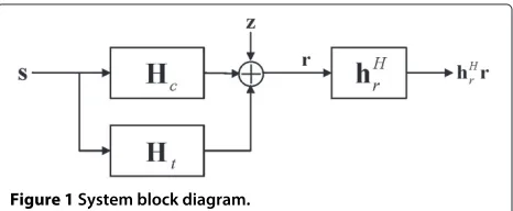
is used to process the receiver signalrat the receive end [12,28], as shown in Figure 1. Thus, the SCNR at the output of the receive filter is defined as
SCNR= E
As a cognitive MIMO radar system has the ability of learning, the prior knowledge of the environment state can be obtained from previous measurements. Using a specific environment database which contains the statis-tics of the target and clutter impulse responses and noise, the statistics of the target returnxtand the clutter return xtcan be derived. Next, we discuss the statistics of the tar-get impulse responseht[n], the clutter impulse response hc[n], and the noisez.
2.1 Statistics of target return
Consider an extended target and assume the length of the target impulse response of the potential extended target is
Ntsuch thatht[n]=0fornin [ 0,Nt−1] andht[n]= 0 otherwise. Then it can be shown from (1) that the target returnxt,ml[n]=0 for allmandlwhennis outside [ 0,N+ Nt−2]. So the number of the observations can be chosen asNR =N+Nt−1. Define the target impulse response vector
Figure 1System block diagram.
ht=
From (2), the statistic of the target return vector xt is determined by the statistic of the target impulse response vectorht, as described in the following lemma.
Lemma 1.GivenHε,s, andhεas in (2), (3), and (6)/(9), Waveform design for MIMO over-the-horizon radar detection, submitted).
In this paper, the target impulse responsehtis assumed to be zero-mean complex Gaussian distributed with covariance matrixRht=E{hεhHε}. Since any linear
trans-formation of a complex Gaussian random vector produces another complex Gaussian random variable [29], thextin (2) also follows a zero-mean complex Gaussian distribu-tion, whose covariance matrix
can be computed using Lemma 1.
2.2 Statistics of clutter return
Define the clutter impulse response vector
hc=
Assume the clutter impulse response vector hc is zero-mean complex Gaussian distributed with known covariance matrix Rhc = E{hchHc}. Thus, xc also fol-lows a zero-mean complex Gaussian distribution, whose covariance matrix
can be computed using Lemma 1.
2.3 Statistics of noise
The noise term z = (z1[ 0] ,. . .,zL[ 0] ,. . .,z1[NR −1] , . . .,zL[NR−1])Tis assumed to obey complex Gaussian distribution with mean zero and covariance matrixRz =
E{zzH} =σz2ILNR, which is assumed to be independent of
the target and clutter returns.
3 Waveform design with constrained bandwidth
In this section, waveform design for the SCNR maximiza-tion problem is introduced for cognitive MIMO radar systems. The waveforms are constructed as LFM signals where the starting frequencies and bandwidths for each of the LFM signals will be optimized. The optimization problem with the constraints of the allowable range of operating frequency and total transmit energy is pre-sented. The method to solve the optimization problem is given subsequently.
3.1 Waveform design for SCNR maximization
Design the waveform transmitted by the mth transmit
antenna at thenth ,n=0,. . .,N−1, discrete-time sample
whereEmis the transmitted energy of themth waveform within the time duration T, Ts is the sampling period,
andfm andbmare the staring frequency and bandwidth of themth waveformsm[n], such that the frequency band occupied bysm[n] is [fm,fm+bm]. UseF to denote the set of allowable operating frequencies. Thus, for any m,
m = 1,. . .,M, the frequency band [fm,fm+bm] should be within the set F. Considering fixed total transmit energy and the constrained allowable frequency band, our goal is to optimize the waveform parameter vector p =[f1,. . .,fM,b1,. . .,bM,E1,. . .,EM] and the receiver
impulse response vector hr to maximize the SCNR as
defined in (5). The optimization problem is given by
max
whereE0is the total transmit energy. The objective
func-tion in (12) is not a convex funcfunc-tion, so that the convex optimization approaches do not work for this problem. Instead, we adopt the iterative approach proposed in [28] to solve the optimization problem in (12). We first fix the waveformpto optimize the receiver impulse response hr, and then fix hr to optimizedp. These two steps are executed iteratively until the stopping criterion is met.
3.2 Optimization with fixed waveform
When the waveform parameter vector p is fixed, the
problem in (12) is reduced to
max
From (8) and (10), the problem in (13) can be rewritten as
DefininguYHhrwhereYis a lower triangular matrix which satisfiesYYH =Rc+Rz, the optimization problem can be expressed in terms ofuas
max u
uHu
uHu , (15)
where = Y−1RtYH−1. Solving the problem in (15)
with Lagrange multiplier method, the solution of u is
obtained as
u=φmax, (16)
whereφmaxis the eigenvector corresponding to the largest eigenvalue of. Thus, the solution ofhris given by
hr,=
YH−1φmax. (17)
3.3 Optimization with fixedhr
where the expressions of EHHt hrhHr Ht
and E
HHchrhHr Hc
are also determined by the statistics ofht in (6) andhcin (9), as described in the following lemma.
Lemma 2.GivenHεin (2),hrin (4), andhεin (6) or (9), theEHHεhrhHr Hε
can be defined in terms of E{hεhHε}, where the ijth entry ofEHHεhrhHr Hε
is given by
EHHεhrhHrHεij=
NR−1
n,n=0 L
l,l=1
hrl[n]h∗rl n E
hεhHε
de,
(19)
where d=N+n− (j−1)/M −1ML+l−1M+
˜
m, e =(N+n− (i−1)/M −1)ML+(l−1)M+ ˜m,
˜
m=((i−1)modM)+1, andm˜=((j−1)modM)+1.
Proof of Lemma.See ( S Wang, Q He, Z He, RS Blum, Waveform design for MIMO over-the-horizon radar detection, submitted to IEEE Transactions on Aerospace and Electronic Systems).
As the problem in (18) is highly nonlinear, it is solved numerically using the interior point method. The opti-mized solution is denoted asp.
3.4 Summary of the iterative method
The above discussed iterative method that solves the problem in (12) can be summarized in the following algorithm:
Algorithm 1
1. Set values for the target and clutter impulse response covariancesRhtandRhcand noise covarianceRzbased on the learning output of the cognitive MIMO radar. Initialize the waveform parameter vectorp(0). Initialize
the iteration indexκ =0.
2. Letκ=κ+1. Computehr,(κ)using (17) based on p(κ−1).
3. Computep(κ)by solving (18) based onhr,(κ).
4. Compute the objective function SCNR(κ)in (12) using p(κ)andhr,(κ).
5. Go back to step 2 untilSCNR(κ)−SCNR(κ−1)<
(in dB).
Then, both of the optimized waveform parameter vec-torpoptand receiving impulse response vectorhr,opt are
achieved. The optimized waveformsoptcan be obtained
by pluggingpoptinto (11).
4 Simulations
In this section, we present a few numerical results.
Assume the cognitive MIMO radar has L = 2 receive
antennas andM = 4 transmit antennas. The total trans-mit energy isE0 = 4. Suppose the allowable operating
frequency band is F =[ 0,B]=[ 0, 2 kHz]. Assume the
time duration of transmit waveforms N = 40 and the
length of the target impulse responseNt=8. The number of the observation isNR=N+Nt−1=47. Assume the σz2in the noise covariance matrix isσz2=40. Assume the covariance matrix of the clutter impulse response vector hcin (9) satisfiesRhc = CT ⊗CS, whereCSdenotes the spatial correlation between clutter impulse responses cor-responding to different transmitter to receiver paths for a fixed time index, andCT denotes the temporal correla-tion between clutter impulse responses corresponding to different time delays for a fixed spatial index [30]. Assume theijth element of the spatial correlation matrixCSis
CS,ij=σS2ρS|i−j|, (20)
whereσS2= 40 andρS = 0.9 denotes one-lag correlation coefficient. The temporal correlation matrixCT is con-sidered by the conventional time-varying autoregressive (TVAR) [31,32] modeling (see [33] for details).
4.1 Optimal waveform design
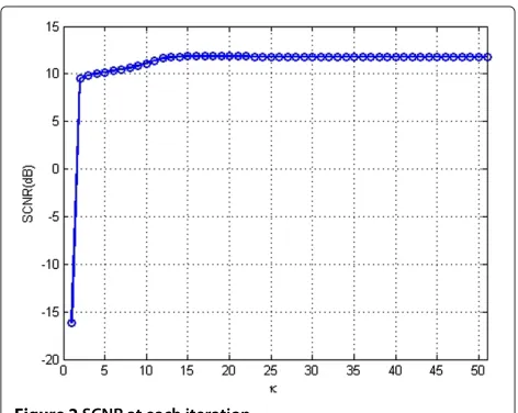
According to the theoretical analysis in Section 3, the opti-mal waveforms should satisfy the optimization problem in (12), which can be solved by applying Algorithm 1. In the simulations, the parameter in the stopping condition of Algorithms is set to be 10−3. The SCNR obtained at each iteration is plotted in Figure 2. Obviously, the value of the SCNR has been converged well before the 51th iteration, so that the parameter vectors obtained at the 51th itera-tion can be regarded as the optimized parameterspoptand hr,opt. The optimized starting frequency, bandwidth, and
transmit energy for each of the waveforms in vectorpopt
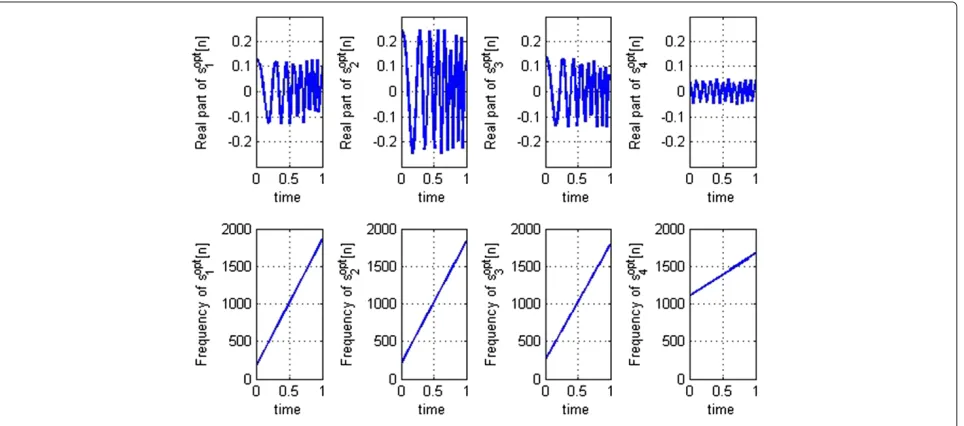
are listed in Table 1. Pluggingpoptinto (11), the designed
Table 1 Starting frequencies, bandwidths, and transmit energies in the waveform parameter vector p for optimized LFM signals
sm[n] fm/Hz bm/Hz Em
m=1 170.35 1,684.6 0.6625
m=2 209.00 1,621.7 2.4429
m=3 255.81 1,537.0 0.7964
m=4 1,100.6 556.60 0.1000
LFM signals are obtained. The real parts and frequencies of the designed LFM signals are shown in Figure 3.
For comparison, the real parts and frequencies of the FS LFM signals, which are commonly used in MIMO radar systems, are plotted in Figure 4. The low-pass component of the mth FS LFM signal at thenth,n = 0,. . .,N−1, discrete-time sample is set as [24-26]
um[n]=
E0
MNexp
j2π
(m−1)fnTs+
Bu 2T(nTs)
2
,
(21)
wheref is the frequency offset between the waveforms sent from two adjacent transmit antennas which is fixed to k/T to attain approximate orthogonality [26], where
k is a positive integer. When the operating frequency is constrained in F =[ 0,B], the Bu should satisfy Bu + (M− 1)f ≤ B. In this example, we let f = 2/T,
Bu=B−(M−1)f, and the value of the other parameters are the same as those in the previous example. Obviously, the optimized LFM signals in Figure 3 and the FS LFM signals in Figure 4 are very different. Unlike the FS LFM signals, where each waveform has identical bandwidth
and the frequency offset between adjacent waveforms are identical, the optimized LFM signals may have differ-ent bandwidths and the offsets between differdiffer-ent pairs of adjacent waveforms may be different, providing more degrees of freedom, which may lead to superior system performance.
4.2 SCNR performance
Now, we compare the SCNR performance of the cogni-tive MIMO radar using the LFM waveforms designed by the proposed method with that of the system using FS LFM signals. Assume that the other parameters are the same as the previous examples. For different values ofM
andE0/σz2, the waveforms are designed and the resulting SCNRs (solid curves) are plotted in Figure 5. The SCNRs obtained using the FS LFM signals (dashed curves) are plotted in the same figure for comparison. The curves with points marked with circles and stars correspond to the cases forM=2 and 4. It is seen that the SCNR curves of the systems employing the optimized LFM signals are uniformly higher than that of the systems employing FS LFM signals, indicating the superiority of our designed signals over the conventionally used FS LFM signals for any tested value ofM. In the studied examples, the SCNR performance is improved when the number of
transmit-ter M is increased from 2 to 4. Thus, employing more
transmit antennas can be helpful in increasing the SCNR. In Figure 6, we consider a cognitive MIMO radar with
M=2 transmitters. For different values ofσS2(20), which is a scaling factor of the clutter covariance matrix, the LFM waveforms are designed using the proposed method and the resulting SCNRs (solid curve with point marked with circle) are plotted in Figure 6. The other simulation
Figure 4Real parts and frequencies of the FS LFM signals.
settings are the same as those used in Figure 5. The SCNRs obtained using the FS LFM signals (dashed curve with point marked with square) are plotted in the same figure for comparison. It is observed that the SCNR decreases with the increase of the clutter covariance scaling fac-torσS2. The SCNR performance of the system using our designed signals is better than that of the system using FS LFM signals for all the tested values ofσS2.
5 Conclusions
In this paper, the waveforms are proposed to be con-structed by a group of LFM signals with undetermined starting frequencies, bandwidths, and transmit ener-gies. The waveform parameters and the receiver impulse
Figure 5SCNR versusE0/σz2curves.SCNR versusE0/σz2curves for systems employing the optimized LFM signals (solid curves) and systems using the FS LFM signals (dashed curves) for different number of transmittersM.
response are jointly designed by maximizing the SCNR performance of a cognitive MIMO radar system under the constraints of allowable range of operating fre-quency and total transmit energy. The algorithm for solving the waveform optimization problem was pre-sented. We showed through numerical examples that the systems using the proposed waveforms have superior SCNR performance than the systems using the FS LFM signals.
Appendix 1 Convolution matrices
From (1), lettingε = t orc, the target or clutter return received by thelth receiver can be expressed as
xε,l[n]=
wheresis the overall waveform vector as defined in (3) andHεdenotes the convolution matrix for target or clutter, in
whichhε,ml[n] is defined in (1).
Competing interests
The authors declare that they have no competing interests.
Acknowledgements
This work was supported by the National Nature Science Foundation of China under Grants 61032010 and 61102142, the International Science and Technology Cooperation and Exchange Research Program of Sichuan Province under Grant 2013HH0006, and by the Fundamental Research Funds for the Central Universities under Grant ZYGX2013J015.
Received: 2 February 2014 Accepted: 24 May 2014 Published: 12 June 2014
References
1. A Aubry, M Lops, AM Tulino, L Venturino, On MIMO detection under non-Gaussian target scattering. IEEE Trans. Inform. Theor.56(11), 5822–5838 (2010)
2. Y Yu, AP Petropulu, HV Poor, Power allocation for CS-based colocated MIMO radar system, inIEEE Sensor Array and Multichannel Signal Processing Workshop(Hoboken, New Jersey, June 2012), pp. 217–220
3. T Aittomaki, V Koivunen, Performance of MIMO radar with angular diversity under Swerling scattering models. IEEE J. Sel. Top. Signal. Process.4(1), 101–114 (2010)
4. P Stoica, J Li, Y Xie, On probing signal design for MIMO radar. IEEE Trans. Signal Process.55(8), 4151–4161 (2007)
5. AD Maio, M Lops, L Ventura, Diversity-integration trade-off in MIMO detection. IEEE Trans. Signal Process.56(10), 4151–4161 (2008) 6. Q He, RS Blum, H Godrich, AM Haimovich, Target velocity estimation and
antenna placement for MIMO radar with widely separated antennas. IEEE J. Sel. Top. Signal. Process.4(1), 79–100 (2010)
7. Q He, RS Blum, Diversity gain for MIMO Neyman-Pearson signal detection. IEEE Trans. Signal Process.59(3), 869–881 (2011)
8. B Friedlander, Waveform design for MIMO radars. IEEE Trans. Aero. Electron. Syst.43(5), 1227–1238 (2007)
9. Y Yang, RS Blum, MIMO radar waveform design based on mutual information and minimum mean-square error estimation. IEEE Trans. Aero. Electron. Syst.43, 330–343 (2007)
10. S Haykin, Cognitive radar: a way of the future. IEEE Signal Process. Mag. 23(1), 30–40 (2006)
11. P Stoica, H Hao, J Li, Optimization of the receive filter and transmit sequence for active sensing. IEEE Trans. Signal Process.60(4), 1730–1740 (2012)
12. A Aubry, AD Maio, M Piezzo, A Farina, M Wicks, Ambiguity function shaping for cognitive radar via complex quartic optimization. IEEE Trans. Signal Process.61(22), 5603–5619 (2013)
13. A Aubry, AD Maio, A Farina, M Wicks, Knowledge-aided (potentially cognitive) transmit signal and receive filter design in signal-dependent clutter. IEEE Trans. Aero. Electron. Syst.49(1), 93–117 (2013)
14. A Aubry, AD Maio, M Piezzo, A Farina, M Wicks, Cognitive design of the receive filter and transmitted phase code in reverberating environment. IET Radar Sonar Navig.6(9), 822–833 (2012)
15. J Bae, NA Goodman, Widely separated MIMO radar with adaptive waveform for target classification, inIEEE International Workshop on Computational Advances in Multi-Sensor Adaptive Processing(San Juan, Puerto Rico, December 2011), pp. 21–24
16. W Li, G Chen, E Blasch, R Lynch, Cognitive MIMO sonar based robust target detection for harbor and maritime surveillance applications, inIEEE Aerospace Conference(Big Sky, Montana, March 2009), pp. 1–9
17. W Huleihel, J Tabrikian, R Shavit, Optimal adaptive waveform design for cognitive MIMO radar. IEEE Trans. Signal Process.61(20), 5075–5089 (2013) 18. YA Nijsure, Cognitive radar network design and applications. PhD thesis,
Newcastle University (2012)
19. M Skolnik,Radar Handbook. (McGraw-Hill, New York, 2008)
20. G Babur, OA Krasnov, A Yarovoy, P Aubry, Nearly orthogonal waveforms for MIMO FWCW radar. IEEE Trans. Aero. Electron. Syst.49(3), 1426–1437 (2013)
21. FG Geroleo, M Brandt-Pearce, Detection and estimation of LFMCW radar signals. IEEE Trans. Aero. Electron. Syst.48(1), 405–418 (2012)
22. Z Wang, F Tigrek, O Krasnov, F Van Der Zwan, P Van Genderen, A Yarovoy, Interleaved OFDM radar signals for simultaneous polarimetric
measurements. IEEE Trans. Aero. Electron. Syst.48(3), 2085–2099 (2012) 23. MA Govoni, H Li, JA Kosinski, Low probability of interception of an
advanced noise radar waveform with linear-FM. IEEE Trans. Aero. Electron. Syst.49(2), 1351–1356 (2013)
25. JJMD Wit, WL van Rossum, AJD Jong, Orthogonal waveforms for FMCW MIMO radar, inRadar Conference(IEEE, Kansas City, Missouri, May 2011), pp. 686–691
26. B Liu, Z He, J Li, Mitigation of autocorrelation sidelobe peaks of orthogonal discrete frequency-coding waveform for MIMO radar, inRadar Conference(IEEE, 2008), pp. 1–6
27. HLV Tree,Detection, Estimation, and Modulation Theory, Part I. (Wiley-Interscience, New York, 2001)
28. C Chen, PP Vaidyanathan, MIMO radar waveform optimization with prior information of the extended target and clutter. IEEE Trans. Signal Process. 57(9), 3533–3544 (2009)
29. S Kay,Fundamentals of Statistical Signal Processing: Detection Theory. (Prentice-Hall, Upper Saddle River, 1998)
30. S Wang, Q He, Z He, RS Blum, MIMO over-the horizon radar waveform design for target detection, inIEEE International Conference on Acoustics, Speech, and Signal Processing (ICASSP)(Vancouver, Canada, May 2013), pp. 4134–4138
31. KB Eom, Time-varying autoregressive modeling of HRR radar signatures. IEEE Trans. Aero. Electron. Syst.35(3), 974–988 (1999)
32. SH Fouladi, M Hajiramezanali, H Amindavar, JA Ritcey, P Arabshahi, Denoising based on multivariate stochastic volatility modeling of multiwavelet coefficients. IEEE Trans. Signal Process.61(22), 5678–5589 (2013)
33. S Wang, Q He, Z He, RS Blum, Waveform design for MIMO
over-the-horizon radar detection in signal dependent clutter and colored noise, inIET Radar Conference(Cincinnati, Ohio, May 2014), pp. 1–6
doi:10.1186/1687-6180-2014-89
Cite this article as:Wanget al.:LFM-based waveform design for cognitive MIMO radar with constrained bandwidth.EURASIP Journal on Advances in Signal Processing20142014:89.
Submit your manuscript to a
journal and benefi t from:
7Convenient online submission
7Rigorous peer review
7Immediate publication on acceptance
7Open access: articles freely available online
7High visibility within the fi eld
7Retaining the copyright to your article