!
"
#"#
$ % %#
&
''' (
Formal Specification of Control Software Systems using Behavioral Views
Ayaz Isazadeh*
Department of computer science University of Tabriz
Tabriz, Iran [email protected]
Jaber Karimpour
Department of computer science University of Tabriz
Tabriz, Iran [email protected]
Habib Izadkhah
Department of computer science University of Tabriz
Tabriz, Iran [email protected]
Abstract: Large-scale control software systems are generally complex to describe, construct, manage, understand, and maintain. This paper approaches to reducing this complexity separate software structural and behavioral descriptions. Much research about control software systems continues on software structures and their patterns, characterizations, and classifications. Currently, research on the behavioral aspect of control software systems includes using formal notations for specifying software behaviors. Large formal specifications, however, can be difficult to create and to understand; more research is needed into methods for assisting software requirements engineers in reducing these difficulties. This paper uses the idea of a software behavioral view. We believe that a fully developed methodology based on views would significantly reduce the complexity of creating and understanding software requirements. This paper deals with the use of view formalism, a state chart based formalism, to specify of control logic for a telephone set system.
Keywords:Formal method; requirement specification; control system software; behavioral views and statecharts;
I. INTRODUCTION (HEADING1)
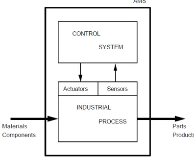
An Automated Manufacturing System typically consists of a controlling system and a controlled system where the controlling system interacts with the controlled system using information available from various sensors [4]. A control system is a device, or a collection of devices that manage the behavior of other devices and are modeled as continuous real-valued functions of real valued time. We denote by "Automated Manufacturing System" (AMS) all kind of automated machine used in industrial factories to process parts or products. Figure 1. gives the general structure of AMS.
Software safety is an important property for safety critical control systems and formality is essential in safety-critical applications, such as embedded control systems used in Manufacturing System, nuclear reactors or airplanes [1] especially those in control systems, whose failure could result in danger to human life, property or environment. It is recently becoming more important due to the increase in the complexity and size of safety critical control systems. Formal software requirements specification is known as a means to increase the safety of such systems in the early phase of software development process. It guides the developer to specify all requirements explicitly without any assumptions or omissions.
In addition, formal specification can be verified using tools such as model checker [1] or theorem prover.
The theory underlying formal software specification languages has developed rapidly in the past few years. Most of current methods for systems specifications are suitable
only for small systems. Requirements engineering of large-scale software systems using current Formal Description Techniques (FDT), is complex and difficult. In general, when the scale of the system grows linearly, the number of states (in FSM-based methods) grows exponentially. Therefore, much research continues on introducing new techniques for eliminating (or at least reducing) this problem.
Figure 1. the general structure of AMS.
problem with formal methods is size. The difficulties of managing a large volume of formal specifications have made formal methods impractical for large systems.
We use the idea of a software behavioral view: intuitively, this is a complete description of the behavior of the system observable from a specific point of view. We define a formal notation, behavioral view (Viewcharts), with a well-defined semantics based on Statecharts. Behavioral view gives a means for precisely describing views and their compositions.
This paper uses a behavioral view concept for formal specification of control system model and this model can be applied the large class of real Flexible Manufacturing System. Using this model, a designer expresses the functional capacities of his system and the product flows.
The remaining parts of this paper are organized as follows: In Section 2, we have a brief review of behavioral views. Section 3, the telephone set specified by behavioral views.
II. BEHAVIORALVIEWS
This section provide a brief over of the behavioral views formalism; a separate paper [2,10] describes it in more detail. The Viewcharts formal notation with well-defined semantics is based on Statecharts. Statecharts, however, has no concept of behavioral views. Viewcharts extends Statecharts to include behavioral views and their hierarchy of composition. This extension enables a systems analyst to specify the behavior of a large scale system by means of its simple views.
A behavioral view of a software system is the behavior of the system observable from a specific point of view. The caller view of a telephone set and telephone set view of a switching system is an example of behavioral views.
In the remainder of this section we provide some informal descriptions of the View concepts. The following section is dedicated to the formal description of the composition of views may require communication between the composed views; the scope of an event in one view. An action belongs to the view that generates the action. Similarly, a variable belongs to the view that declares it. The scope of a variable declared by a view is the view and all its sub views. An event or an action may have multiple owners while variables cannot. This notion of ownership, in behavioral views, adds name space control to limit the scope of broadcast communication, solving a problem with Statecharts[3,5].
B. Composing Behavioral Views
Views can be composed in three ways: SEPARATE, OR, and AND. Except for the effect of ownership and scoping restrictions the OR and AND compositions of views, in behavioral views, are similar to the OR and AND compositions of states, in statecharts, respectively. The SEPARATE composition of views, all the views are active if any one of them is active and no transition between the
views is allowed. In an OR composition only one view can be active, and there can be transitions between the views. Notice that a transition from a source view to a destination view interrupts the source view, i.e., takes the system out of any state(s) of the source view; it is, therefore called an interrupt transition. In case of a conflict between the interrupt transition and one internal to the source view, the interrupt transition has higher priority. Visually, the views involved in a SEPARATE composition are drawn on the top of each other, as shown in Figure 2, giving the impression that they are located on different planes and, consequently, are hidden from each other.
In an AND composition of views, all the views are active. The scope of all elements owned by each view is extended to the other views. Behavioral view adopts Harel’s synchrony hypothesis that events are instantaneous. Specifically, events, action, and checking the value of a condition expression ideally take no time; therefore, transitions are also instantaneous [4].
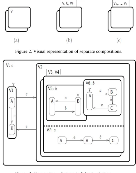
Figure 2. Visual representation of separate compositions.
Figure 3. Composition of views in behavioral views.
scopes of the elements owned by a superview covers all its subviews.
The behavioral views of Figure 3, for example, is composed of a SEPARATE composition of V5 and V6, which in turn is ANDed with V7 forming v3. A SEPARATE composition of two identical views V3 and V4 forms V2. The full view V is an OR composition of VI and V2.
C. Effect on transitions
The following examples demonstrate the way in which the compositions affect transitions with the same label. Recall (Section 2.1) that a view can trigger the events it owns. Assuming that the system described by the viewchart
of Figure 3 is in sub configuration
{V3.V5.B,V3.V6.A,V3.V7.A},
[a] if the view V3.V7 triggers a, then the sub-configuration will change to {V3.V5.A, V3.V6.B, V3.V7.B}; [b] if the view V triggers c, non deterministically, then the
entire system configuration will change to either (V1.A) or (V1.B);
[c] no other event can change the sub-configuration. Assuming that the system is in sub-configuration {V3.V5.A, V3.V6.B, V3.V7.B},
[d] if the view V3.V5 triggers b, then the sub-configuration will change to {V3.V5.B, V3.V6.B, V3.V7.C}; [e] if the view V3.V6 triggers b, then the sub-configuration
will change to {V3.V5.A, V3.V6.C, V3.V7.C}; [f] if the view V triggers c, non deterministically, then the
entire system configuration will change to either (V1.A) or (V1.B);
[g] No other event can change the sub-configuration. Assuming that the system is in sub configuration {V3.V6. C},
[h] if the view V triggers c, non deterministically, then the sub-configuration will change to {V3.V6.A} or the entire system configuration will change to either (V1.A) or (V1.B);
[i] No other event can change the sub-configuration.
III.TELEPHONESYSTEM
The behavioral views notation is designed to specify the behavioral requirements of large-scale complex systems; and we can do it on a need-to-specify basis. In behavioral views, we do not have to specify the full behavior of the system; therefore, we are not concerned with the complexity or scale of the system. A complex system may have many different features; we specify only the features of our interest, i.e., our view of the system.
We present behavioral views specification of a telephone service provided by a Plain Old Telephone System (POTS). Their informal description of POTS includes the diagrams shown in Figure 4 and 5 the diagrams are self explanatory. A LOTOS specification of this service is also given by Faci and others [8]. The timing aspect of POTS is missing from the LOTOS specifications, because timing aspects cannot be specified in LOTOS. As the specifiers state, for example, LOTOS cannot deal with a specification element such as "the telephone can only be off hook for a maximum of 20 seconds, after which it would be disconnected". Viewcharts specification, on the other hand, includes the timing aspects of POTS.
We want to specify a telephone service provided by POTS. That is only one of the many behavioral views of POTS (and we will still specify it as a composition of even simpler behavioral views).
Figure 4. A high level scenario for establishing a telephone connection (From [8]).
Figure 5. A detailed scenario for establishing a telephone connection (From [8]).
Accounting, routing, diagnostics, maintenance, and other aspects of POTS have their own views of the system and can be specified as separate behavioral views.
The behavioral views specification of POTS consists of a separate composition of many, but a finite number of, identical views called CALLs. A CALL is the behavioral view of POTS with respect to a single telephone connection. Each CALL, in turn, is composed of three behavioral views: CALLER, the caller view of a telephone set, CALLED, the called view of the set, and CONTROLLER, the telephone set's view of POTS.
A. Specifying Behavioral Views
fact, as far as our specification is concerned, an implementer may choose to deliver two devices: one for CALLER and the other for CALLED.
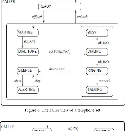
Figure 6 shows the caller view of a telephone set. The view specifies that the telephone by default is in the READY state. When a caller picks up the handset, an event offhook is triggered by CALLER and the telephone set enters to the state of WAITING. In addition to the event offhook, the view CALLER also owns the events st(DIALING), which occurs when the user starts dialing, and onhook, which occurs when the user hangs up. (These events must be declared by CALLER; for clarity, however, in this and the following views, wherever the ownership of an element is obvious, we have omitted the corresponding declaration from the views.) All other events be long to CONTROLLER and are described below. As far as CALLER is concerned, however, they are events that CALLER expects to occur and upon their occurrences it behaves as specified.
Figure 6. The caller view of a telephone set.
Figure 7. The called view of a telephone set.
Figure 7 shows the called view of a telephone set. This view owns only the events offhook and onhook. All other events belong to CONTROLLER. The figure is self-explanatory. Figure 8 shows the view CONTROLLER. It provides the interactions between CALLER and CALLED. The view CONTROLLER owns all the events that occur in this view, except those that belong to CALLER or CALLED. CONTROLLER also declares the ownership of n (a variable used for the caller's telephone number), m (a variable used for the called's telephone number), and x (a temporary variable). In addition, CONTROLLER uses another variable
B (the set of busy numbers) which is global to CONTROLLER.
Figure 8. A telephone set's view of POTS.
As the figure shows, CONTROLLER is ready for the offhook event of CALLER. This event triggers an action st(B := B U {n}), which means "start adding n to the set B". The time-consuming activity of adding n to B takes place in the state PROCESS.ADDING. The completion of this activity triggers the event done which, in turn, triggers the action st(DT). The actions st(DT), st(BS), and st(RS), start dialtone, busy signal, and ring signal, respectively. rd(m) is an event that occurs when m, the called's telephone number is read. The action st([
m
∈
B
]) starts checking whether or not m is in B, i.e., whether or not the called party is busy. Again, the checking activity takes place in the state CHECKING. Finally, the event tm(en(PROCESS); t) occurs at exactly t time units after the time that the system enters to the PROCESS state. The rest of the specification in Figure 8 should now be self-explanatory.Figure 9. A behavioral view for the telephone service provided by POTS.
B. Composing Behavioral Views
A separate composition of CALLER and CALLED forms the view PHONE, which describes the behavior of the system observable at the two ends of a telephone line. each other except for sharing the variable B.
C. Discussion
The Statecharts specification of POTS would require extending Statecharts to support parameterized repetition of AND-states. Without parameterized states, considering the number of CALLs, the Statecharts specification of POTS will not be practical. Recognizing this fact, Harel describes that such an extension "represent significant potential strengthening of the Statecharts formalism as a tool for specifying real systems" [9]. Assuming that Statecharts is extended to support this capability, Harel provides an informal diagram of a portion of a statechart that would specify a telephone system (Figure 10).
Figure 10. A portion of a statechart specifying POTS (From [9]).
This diagram does not show the complete picture of the statechart; but we can still see how much more easily our behavioral view specification of POTS expresses the specification compared to Statecharts. Notice that the telephone states of the statechart is similar to the CALL views of our behavioral view. However, the telephone states are ANDed, while the CALL views are separated.
Therefore, in the statechart we have to make sure that all the elements are uniquely specified within the 10,000 orthogonal states; and to do that we have to use parameters like i and j (e.g., receiver i lifted, receiver j replaced, etc.). In the behavioral view, on the other hand, there is no need for these parameters. As mentioned in the previous example, the parameters are within the structure of the behavioral view.
The diagram of Figure 10 does not show a portion of the statechart, the controller, that establishes the connections between telephones. The controller must be ANDed with all telephones. To get an idea of the complexities associated with expressing the behavior of the controller, note that if the network had only two telephones, then we could express the behavior of the controller as the CONTROLLER view of our behavioral view (Figure 8). The network, however, has
many telephones and we have to express the behavior of a controller that interacts with many telephones. Many telephones may request call setup independent of each other. We have to specify the way in which the controller must uniquely identify all these telephones and respond to their concurrent requests. Consequently, compared to our behavioral view specification, we have to provide
[a] more details to uniquely identify the telephones and the events they generate;
[b] An additional component, a queuing mechanism, to handle the concurrent requests.
We do not see any of these details in our behavioral view specification of POTS. The details are implicitly provided by our notion of views and their compositions. In summary, when we specify the behavioral requirements of a system by a behavioral view, part of the specification is expressed implicitly by the structure of the behavioral view. The specifications therefore, are expressed more easily in behavioral view compared to Statecharts.
IV. CONCLUSIONS
A large-scale control software system may exhibit a combination of many different and identical behavioral views. The behavioral view notation allows these views to be specified as stand-alone systems and provides a method of composing them to form the overall system behavior specification. It is important, however, to realize that composing behavioral views is different from integrating them. Consequently, since large-scale control system behavior can be described in terms of simple behavioral views, Viewcharts simplifies the specification by reducing it to the specifications of behavioral views.
V. REFERENCES
[1] Junbeom Yoo, Taihyo Kim. 2005. A formal software requirements specification method for digital nuclear plant protection. The Journal of Systems and Software 74 , 73–83
[2] A. Isazadeh, D. A. Lamb, and G. H. MacEwen. 1996. Viewcharts: A behavioral specification language for complex systems. In Proceedings of International Workshop on Parallel and Distributed Real-Erne System (WPDRTS), pages 208- 215, Honolulu, Hawaii. IEEE Computer Society Press.
[3] D. Harel. 1987. Statecharts: A visual formalism for complex systems Science of Computer Programming, 8:23 1-274.
[4] Amir A. Khwaja, Joseph E. Urban. 2009. RealSpec: An Executable Specification Language for Modeling Control Systems. IEEE International Symposium on Object/Component/Service-Oriented Real-Time Distributed Computing
[5] D. Hard and A. Naamad. 1995. The STATEMATE semantics of Statecharts. Technical report, i-logix, Inc., 22 Third Avenue Burlington, Mass. 01803, USA. [6] K. L. Heninger, J. W. Kallander, J. E. Shore, and D. L.
arnas. 1978. Requirements for the A-7E aircraft. Technical Report NRL 3876, Naval Research Laboratory, Washington, DC.
[8] M. Faci, L. Logrippo, and B. Stepien. 1991. Formal specification of telephone systems in LOTOS: The constraint-oriented approach. Computer Networks and ISDN Systems, 21:53-67.
[9] D. Harel. 1987. Statecharts: A visual formalism for complex systems. Science of Computer Programming, 8:231-274.
![Figure 4. A high level scenario for establishing a telephone connection (From [8]).](https://thumb-us.123doks.com/thumbv2/123dok_us/708544.1079050/3.612.324.553.98.270/figure-high-level-scenario-establishing-telephone-connection.webp)
![Figure 10. A portion of a statechart specifying POTS (From [9]).](https://thumb-us.123doks.com/thumbv2/123dok_us/708544.1079050/5.612.66.282.312.478/figure-portion-statechart-specifying-pots.webp)
