Volume 8, No. 5, May-June 2017
International Journal of Advanced Research in Computer Science RESEARCH PAPER
Available Online at www.ijarcs.info
ISSN No. 0976-5697
Steganography using Bit Plane Complexity Segmentation and Artificial Neural
Network
Rashmeet Kaur Chawla
IT DepartmentSGTBIMIT Delhi, India
Sunil Kumar Muttoo
Department of Computer ScienceUniversity of Delhi Delhi, India
Abstract: Steganography is a technique to hide information in some other vessel data without leaving any apparent evidence of vessel data alteration. There are different techniques for steganography namely substitution technique, transform domain technique, spread spectrum technique, statistical method, distortion technique and cover generation technique. The three characteristics which are taken care of are:- capacity, undetectibility and imperceptibility. Multilayer neural network is used to achieve image compression. The input pixels are used as target values and the hidden layer output is the compressed image. Our proposed technique uses an image as the vessel data and embeds a secret image that is compressed by artificial neural network in the bit-planes of the vessel image without deteriorating image quality. This technique makes use of the characteristics of the human vision system whereby a human cannot perceive any change in the information in a very complicated binary pattern. Its information hiding capacity can be made large.
Keywords: Steganography, Information hiding, Multilayer neural network, image compression, Hidden layer, Vessel image.
I. INTRODUCTION
To conceal the very existence of transmission we use steganography. Encryption clearly marks a message as containing “interesting” information and the encrypted message becomes subject to attack. So, a typical steganographic technique may use image data as the container of secret information. Some of the techniques use least significant bits of the image pixels to hide the data while others embed the secret information in a specific band of spatial frequency component of carrier. [3]
Image compression has been an active area of research since the inception of digital image processing. Compression is achieved by exploiting the redundancy in an image. Artificial Neural Network have found increasing applications in this field due to their noise suppression and learning capabilities. [1]
In this paper we have proposed a technique for Steganography using bit plane complexity segmentation and artificial neural network.
Some of the concepts used are as follows:-
1. Back Propagation Neural Network
An Artificial Neural Network (ANN) is a computational model based on the structure and functions of biological neural networks. They are considered nonlinear statistical data modelling tools where the complex relationships between inputs and outputs are found. [6]
Back Propagation Neural Network is designed and trained using different learning algorithms. The neural network structure shown in Figure1 has three layers: one input layer, one output layer and one hidden layer. Both of input layer and output layer are fully connected to hidden layer. [2] The connection weights in the network are gradually adjusted, working backwards from the output layer, to the input layer through the hidden layer, until correct output is produced. The general parameters deciding the performance of back propagation neural network algorithm includes
mode of learning, target values, goal, epochs, learning rate and momentum factors. [2]
Compression is achieved by designing the value of the number of neurons at the hidden layer, less than that of neurons at both input and output layers. The above neural network could be either linear or nonlinear network according to their activation function. [2]
Figure 1
1.1 Network Training Algorithms
Training the network is an important step to get the optimal values of weights and biases after being initialized randomly or with certain values. For training the network, the 128x128 pixels image has been employed. [1]
During training, the weights and biases of the network are iteratively adjusted to minimize the network performance function which is the mean square error for the feed forward networks. The mean square error is calculated as the average squared error between the inputs and targets. [1]
In the basic back propagation training algorithm, the weights are moved in the direction of the negative gradient, which is the direction in which the performance function decreases most rapidly. It can be written as: Xk+1 = Xk - αkgk +1 , where Xk+1 is a vector of current weights and biases, gk is the current gradient, and ak
Training could be started by making target matrix equal to input matrix. Different training algorithms can be used, mainly classified as fast algorithms(example trainbfg,
trainoss, trainlm, etc.) and slow algorithms (example traingd, traingda, etc.)
1.2 Simulation of Results
After training, we obtain a simulated network by the input matrix and the target matrix. In the simulation process two outputs are obtained, the hidden layer output and the output layer output. The hidden layer produces a matrix of 16x256, whereas the output layer produces a matrix of 64x256. Hidden layer output is the compressed image where hi<ni, where hi is the number of neurons in hidden layer and ni is the number of neurons in the input layer. [2]
In the hidden layer matrix, each column should be reshaped into 4x4 pixel blocks, while in the output layer matrix, each column should be reshaped into 8x8 pixel blocks to display both matrices as images. [1]
II. STEGANOGRAPHY
Steganography literally means covered writing and is the art of hiding secret messages within another seemingly innocuous message or carrier. The advantage of steganography is that the intended secret
message does not attract attention to itself as an object of scrutiny.
The carrier used is a grey scale image and the hidden image appear to be hidden (or be part of) the cover image. Steganography includes the concealment of information within computer files. In digital steganography, electronic communications may include steganographic coding inside of a transport layer, such as a document file, image file, program or protocol. [4]
2.1 BPCS Technique for Steganography:
• Canonical Grey Code
In PBC the substantial portions of the regions on the higher bit planes are relatively flat in color (mostly all 0s or all 1s). This is because of the “Hamming Cliffs” which occur with PBC wherein a small change in color affects many bits of the color value.
In binary:
127 = 01111111 & 128 = 10000000 In gray code:
127 = 01000000 & 128 = 11000000
In gray code the representation of adjacent gray levels will differ only in one bit(unlike binary format where all the bits can change). CGC images do not suffer from such Hamming Cliffs.
• Complexity of an image
The complexity of an image(α) is defined by the following: α =k/The maximum possible B-W changes in the image, where, k is the total length of black-and-white border in the image.
So, value of α ranges over 0≤ α≤1.
• Conjugation of a binary image:-
It is applied when the complexity of the vessel image block is less than the threshold and cannot be used for embedding the secret data.
P * = P XOR Wc,
where P* is a conjugated 8x8 block of vessel image, P is an informative (i.e. less complex) 8X8 block of vessel image, Wc is a complex binary pattern with a white pixel at the upper left corner position.
Wc pattern
After conjugation, complexity of the vessel image block increases and thus can be used for embedding secret data.
α(P*) = 1 – α(P). [3]
III. PROPOSEDTECHNIQUE
With this proposed technique, we can hide a larger size secret image into vessel image after compressing it using artificial neural network. This is extremely important for efficient storage and transmission of image data. Multilayer neural network has many advantages like noise suppression, learning capabilities and can accurately approximate to any linear or non-linear function. It is thus perfect to be used for image compression.
In [1] the Image compression technique and in [2] BPCS technique is described. The proposed technique is described in algorithm 1 and algorithm 2.
Algorithm 1 for the Image Compression:-
1. Take a 128x128 grey scale secret image. Divide it into 8x8 pixel blocks and reshape each one into 64x1 column vector.
2. Arrange the column vectors into a matrix of 64x256, which will be used as input matrix.
3. Let the target matrix equal to the input matrix obtained in step 2.
4. Choose a suitable learning algorithm such as traincgf and parameters like goal – 0.001 to start training the neural network using neural network toolbox of matlab.
5. Train and simulate the network with the given input matrix and the target matrix.
6. Obtain the output matrices of the hidden layer and the output layer.
7. Post-process them to obtain the compressed image and the reconstructed image respectively.
We take a 128x128 grey scale secret image and divide it into 8x8 pixel blocks. Then reshape each one into 64x1 column vector. We arrange these column vectors into a matrix of 64x256, which will be used as input matrix named as sample. Let the target matrix equal to the sample matrix. Then we use the neural network toolbox of matlab to create, train and simulate an artificial neural network.
Explanation for the above algorithm is as follows:-
a matrix of 16x256, whereas the output layer produces a matrix of 64x256. We post-process them to obtain the compressed image of size 64x64 and the reconstructed image of size 128x128.
Algorithm 2 for the BPCS technique:-
1. Transform the grey scale vessel image from PBC to CGC system.
2. Divide our vessel image into a series of bit planes (1-8). 3. Segment each bit-plane of the vessel image into informative and noise-like regions by using a threshold value (α=0.3).
4. Divide the secret file into a series of 8 x 8 secret blocks. 5. If a block (P) of cover image is less complex than the threshold (α), then conjugate it to make it a more complex block (P*). (Provided it is not used for embedding the watermark or the signature)
6. If the block is conjugated, then record this fact in a “conjugation map”. Embed the conjugation map in the noise block with the highest entropy.
7. Embed each secret block into the noise-like regions of the bit-planes (or replace all the noise-like regions with a series of secret blocks).
8. Generate a new stego image using modified bit planes. 9. Convert the stego image from CGC back to PBC.
We take a 256x256 grey scale image which is used as the vessel image. It is converted from PBC to CGC form before starting the algorithm. We divide the vessel image into 8 bit planes using bitget() function of matlab. Then each bit plane is segmented into informative and noise like regions by using a threshold value α. We divide compressed secret file of 64x64 size into 8x8 blocks.
Explanation for the above algorithm is as follows:-
If a block (S) of the vessel image is less complex than the threshold (α0), then we make it more complex (S*) α(P*) = 1 – α(P) by conjugation. If the block is conjugated, then it
is recorded in a “conjugation map”. We embed the
conjugation map in the noise block of the vessel image with the highest entropy. Embed each secret block into the noise-like regions of the bit-planes. At the end, we convert the stego image from CGC back to PBC.
IV. EXPERIMENTALRESULTS
Fig 1.1 a), b) represent original vessel image and secret data respectively.
[image:3.595.309.554.59.661.2]
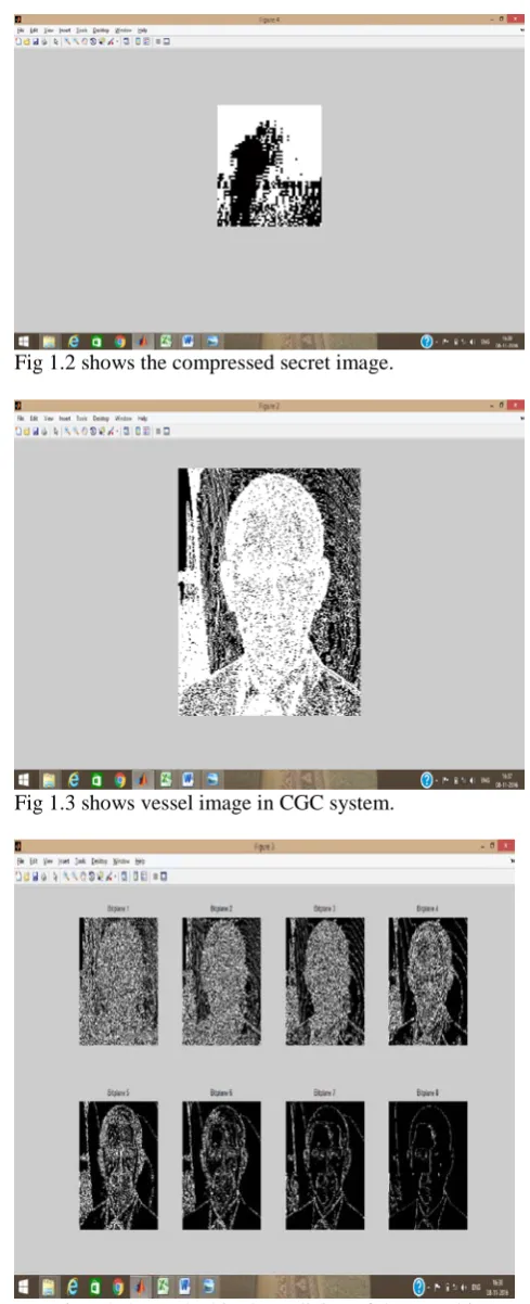
Fig 1.2 shows the compressed secret image.
Fig 1.3 shows vessel image in CGC system.
[image:3.595.312.549.437.655.2] [image:3.595.34.282.561.738.2]
Fig 1.5 shows the image reconstructed from the compressed secret image.
Fig 1.6 a), b) shows the original vessel image and vessel image obtained after embedding secret file in CGC system.
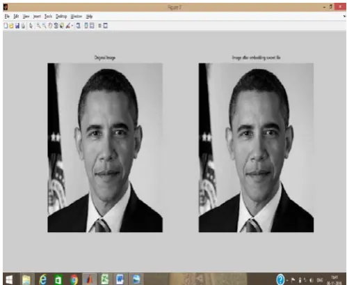
Fig 1.7 a), b) shows the Original vessel image and vessel image which is obtained after embedding the secret file.
V. ANALYSIS
The following table shows PSNR values between original vessel images and vessel images obtained after embedding different secret files in different formats. These PSNR values indicate that the robustness of the technique is preserved.
S.No. Vessel image used
Secret image used
PSNR Value
1 Test 1.gif Secret 1.bmp 51.2633
2 Test 2.bmp Secret 1.bmp 51.2988
3 Test 3.bmp Secret 1.bmp 51.1832
4 Test 4.jpg Secret 1.bmp 51.2254
5 Test 5.png Secret 1.bmp 51.2121
6 Test 6.gif Secret 1.bmp 51.2966
7 Test 7.jpg Secret 1.bmp 51.2298
8 Test 8.png Secret 1.bmp 51.2681
9 Test 9.gif Secret 1.bmp 51.2617
10 Test 10.jpg Secret 1.bmp 51.2693
11 Test 1.gif Secret 2.jpg 51.2461
12 Test 2.bmp Secret 2.jpg 51.3007
13 Test 3.bmp Secret 2.jpg 51.2058
14 Test 4.jpg Secret 2.jpg 51.2430
15 Test 5.png Secret 2.jpg 51.2227
16 Test 6.gif Secret 2.jpg 51.2797
17 Test 7.jpg Secret 2.jpg 51.2352
18 Test 8.png Secret 2.jpg 51.2769
19 Test 9.gif Secret 2.jpg 51.2696
20 Test 10.jpg Secret 2.jpg 51.2514
21 Test 1.gif Secret 3.png 51.2887
22 Test 2.bmp Secret 3.png 51.3089
23 Test 3.bmp Secret 3.png 51.1771
24 Test 4.jpg Secret 3.png 51.2356
25 Test 5.png Secret 3.png 51.1956
26 Test 6.gif Secret 3.png 51.2808
27 Test 7.jpg Secret 3.png 51.2575
28 Test 8.png Secret 3.png 51.2965
29 Test 9.gif Secret 3.png 51.2727
30 Test 10.jpg Secret 3.png 51.2593
Test 1.gif
[image:4.595.36.280.279.503.2] [image:4.595.34.284.546.750.2]
Test 3.bmp
Test 4.jpg
Test 5.jpg
Test 6.gif
Test 7.jpg
Test 8.jpg
Test 9.gif
Test 10.jpg
a),b) original image test 8.png and image test 8.png after embedding secret file respectively.
The following table shows PSNR values between original secret images and reconstructed secret images obtained after training and simulation of neural network. These PSNR values indicate that the robustness of the technique is preserved.
S.No. Secret Image used PSNR value
1 Secret 1.bmp 60.2917
2 Secret 2.jpg 60.6900
3 Secret 3.png 60.2443
4 Secret 4.bmp 60.8298
5 Secret 5.png 60.7043
6 Secret 6.gif 59.5828
7 Secret 7.gif 59.1863
8 Secret 8.gif 57.7780
9 Secret 9.gif 59.9990
10 Secret 10.png 58.1925
Secret 1.bmp
Secret 2.jpg
Secret 3.png
Secret 4.bmp
Secret 5.png
Secret 6.gif
Secret 7.gif
Secret 9.gif
Secret 10.png
a)Original Barbara.png b)Reconstructed barbara.png
a) Original p1.png b) Reconstructed p1.png
VI. COMPARISONWITHTHEEXISTINGWORK
The following graph indicates the comparison of psnr values of the ten test images (secret image used is secret 1) between the original work and the proposed work.
The following graph indicates the comparison of psnr values of the ten test images (secret image used is secret 2) between the original work and the proposed work.
The following graph indicates the comparison of psnr values of the ten test images (secret image used is secret 3) between the original work and the proposed work.
VII. APPLICATIONS
1. TRANSACTION TRACKING
Watermarks record the recipient in each legal sale or distribution of the work. If the work is misused (leaked to the press or illegally distributed), the owner could find out about who is the traitor. Visible watermarking is often adopted in this application but invisible watermark is even better.
2. FORENSIC AND PIRACY DETERRENCE
maliciously or unintentionally, quickly and accurately identify the source of leaked content, provide irrefutable evidence of content misuse in support of legal action, gain visibility over where and how their content is being accessed.
3. COPY CONTROL
It combines every content recorder with a watermark detector. When a copy-prohibit watermark is detected, the recording device will refuse to copy.
4. DOCUMENT AND IMAGE SECURITY
Images and documents are distributed to remote offices, agencies, distributors, dealers and must be managed to ensure confidential information is not leaked before the launch date.
VIII. CONCLUSION
• The most important point in this technique is that human eye cannot perceive any change in the information in the bit-planes of an image, thus protecting the copyright of image.
• By using artificial neural network for image
compression, we are able to use a larger size secret image for hiding in the vessel image.
Thus this technique is effective for both storage and transmission of data. Also with BPCS steganography, there is an increase in level of secret and secure communication.
IX. REFERENCES
[1] https://www.researchgate.net/publication/229026489_Image_ Compression_Using_Neural_Network
[2] Daneshwari i. Hatti, Savitri Raju and Mahendra m. Dixit, Design of neural network as data flow model for image compression, International Journal of Image Processing and Vision Sciences (IJIPVS) ISSN(Print): 2278 – 1110, Vol-1 Iss-3,4 ,2012.
[3] Eiji Kawaguchi and Richard O. Eason, Principle and applications of BPCS-Steganography,1999, SPIE 3528, Multimedia Systems and Applications, 464, Conference Volume 3528.
[4] https://en.wikipedia.org/wiki/Steganography
[5] https://www.cmlab.csie.ntu.edu.tw/~ipr/ipr2005/data/material/ [Digital%20Watermarking%2001%20&%2002]%20Applicati ons%20and%20Properties%20of%20Watermarking.pdf [6]