Available online at www.ijrat.org
397
A Literature Review on High Gain dc-dc Boost
Converter
Vinod Shrivastava
1*, Shimi S.L
2, Abhishek Kumar Gupta
3Department of Electrical Engineering1,2,3,NITTTR,Chandigarh1,2, Jamia Millia Islamia, New Delhi3 Email: [email protected]*,[email protected], [email protected]
Abstract-In the recent years the use of commercial sources like coal, diesel, nuclear etc have been increased. In the coming years the conventional sources may evanesce. So, now the prime concern of the engineers and researchers are shifted towards the non-conventional sources such as solar plants, fuel cells, batteries, wind power etc. But the problem in most of these sources is deliver very low and unstable voltage and such sources are not good for commercial use. So, to utilize these non-conventional sources it is required to tie the supply to grid. dc-dc converters are widely used in PV applications. Many researchers presented advancements in dc-dc converter topologies in literature. This paper presents the wide review on recent topologies of dc-dc converters.
Index Terms-High gain dc-dc boost converter; high voltage gain; interleaved boost converter; magnetic coupling; switched inductor; multi-level; multistage; switched capacitor; voltage multiplier cell.
1. INTRODUCTION
Industries have very much requirement of dc-dc converters in now days. Variable dc source improves the performance of industrial applications. Various dc-dc boost converters are available for conflicting power conversion applications. These dc-dc converters are very famous in non-conventional sources as well as most popular in medical, physics, military etc. Basically boost converters having high demand where high dc voltage is required [1]. Based on these requirements this paper presents different techniques for obtaining high gain than normally boost converters.
Non-conventional energy sources increases the electrical power magnitude. Solid fuel creates pollution so power converter topologies are very useful for next stage of power generation. The PV panels gives the output voltage in order of 20-60V. dc-dc boost converters are widely applied for interfacing between the PV panels and inverter-load combination. In PV panel high boost up is required for voltage gain. Full bridge inverter requires approx 380 volts for input [2].
2. VOLTAGE BOOSTING TECHNIQUES
There are many voltage boosting techniques are available now days. This paper presents these different types of voltage boosting techniques, their advantages, disadvantages and applications.
2.1. Multistage technique
This technique employs the combination of various stages of converters in miscellaneous connection. This method consists of cascaded, interleaved and multilevel converter techniques. The voltage gain of
these techniques increases exponentially or linearly based on the based method.
2.1.1. Cascaded Converters
Bidirectional power flow capability is the basic requirement of dc-dc converters. Due to this property regenerative energy can be absorbed and stored in the energy storage system. Besides of this some application requires overlapping input-output voltage limit.
Middle inductor is used in cascaded buck-boost converter. This topology is shown in fig.1. In this technique an interfacing inductor is used between input and output stages [3].
Fig.1 Cascaded Buck Boost Inductor
The voltage of battery is typically much lower than the bus voltage of DC with a high voltage stage in the vehicles driven by electricity. But the overlapping may happen between the battery voltage and the dc bus voltage which depends on the battery’s characteristics and its design of the system. So it is also a prime concern of the researcher, the converter must able to carry the voltage of output side and input side with the range of overlapping.
The cascaded proportional integral control may lead to system unstable during operating time. So to maintain the system stability, Mukherjee et. al. [4] taken a series connected dc-dc topology.
398 a. Some type of sources in converters like
batteries [5-10], fuel cells and super capacitors [11]-[12].
b. Different types of sources in converters, like stand alone photovoltaic system with battery, or solar/wind hybrid energy system [13]-[16].
c. Varying operating conditions at same type of sources in converter the varying conditions may be the photovoltaic panels under different partial shading [17]-[18].
A duty cycle based model predictive control (DC-MPC) technique proposed by Wei et. al [19] to achieve input voltage sharing (IVS) and output voltage sharing (OVS) for an input series output series (ISOS) converter. Wei et. al also proposed a discrete time optimized model of an input series output series type converter and the optimized duty cycles for input voltage sharing and output voltage sharing are predicted with a cost function. The proposed technique compared with the conventional proportional integral (PI) controller based technique. According the comparison of results the proposed duty cycle based MPC technique is better for input voltage sharing and output voltage sharing due to its simplicity, lower cost and higher dynamic performance.
Fig.2. shows the schematic diagram of hybrid cascaded dc-dc converter. As the Fig.2.shows a poly phase converter, in which each phase is controlled by a controllable switch and constructed by switches and energy storage device. The energy storage devices can store some amount of energy from one dc side to other dc side with the help of switches. The poly phase arrangement is modification of single phase switching action and overcome the problem of energy flow interruption in single phase switching action [20].
Fig.2HCDC 2.1.2.Interleaved Converter
The traditional bidirectional buck-boost (CBB) converter is low cost non-isolated and simple construction. Chen et. al.[21] proposed a topology consists bidirectional buck-boost converter with the coupled inductor. Mohammadi et. al.[22] proposed the family of soft switching bidirectional converters with high ZVS range. Non-isolated bidirectional dc-dc converters have been discussed in [23]-[25].
Bahrami.H [26] et.al proposed a novel technique which provides reduced ripple current during the operating at the battery side in the high current
inductors, soft switching and high VGR. This topology is the combination of interleaved cascaded buck-boost converters and the DAHB converter. In series connection the voltage stress on main switches reduced and voltage gain increased.
Xuefenget.al [27] has presents A High Gain Input-Parallel Output-Series DC/DC Converter with Dual Coupled-Inductors. This topology also has a voltage multiplier module. The primary windings of two coupled inductors are parallel connected for sharing the input current and for reducing the input current ripple. On the other hand this converter has the all features of interleaved series connected output capacitors for large output voltage, less ripples in voltage output and less switch voltage stress. The secondary sides of two-coupled inductors are also connected in series with a regenerative capacitor with a diode for increasing the output voltage. The active switches become ONN at zero current and the diode’s reverse recovery problem increases due to leakage inductance of the coupled inductors. The energy of leakage inductance can be recycled in this converter. Hu.et.al [28] proposed an isolated ultra high step up dc-dc converter in matrix transformer configuration for increasing the power level and improving the fault tolerant by a fly back converter. Fault tolerant capability can be increased in this case. Voltage stress on switching element and transformer size can be reduced easily in this technique.
Prabhalaet.al [29] proposed a dc-dc converter with high voltage gain and two input boost stages. It is inspired from a Dickson Charge Pump [20]. The voltage multiplier cells are used to increase the voltage gain. The voltage gain is depending on number of stages and duty cycle of the input stage.
Zhang et.al [30] proposed an interleaved switched capacitor bidirectional dc-dc converter with wide voltage range for energy storage system. In this technique an interleaved structure is added in the LV side to reducing the ripples of current by LV side. Similarly a series connected structure is adopted on HV side of converter for achieving the voltage gain. These converters also have high efficiency.
2.1.3.Multilevel Converter
Available online at www.ijrat.org
399 modular multilevel converter has gaining more
importance compared to others because of its low dv/dt, low harmonics, scalability and modularity. It also has low switching losses.
[image:3.595.89.275.249.327.2]Fault tolerant capability is more in important in converters which is a reason for high attention towards fault tolerant multilevel converter for HVDC applications. These topologies use full bridge sub module. Due to this, this topology uses large number of semiconductor switches. Mathew et. al [38] presents a generalized cross connected sub module with less number of switches with same features of FBSM as shown in Fig.3.
Fig.3 5 level X-SM structure
2.2. Switched Capacitor (Charge pump)
Non-conventional sources like solar and fuel cell preferred low voltage range for operation but grid tied systems requires high voltage range. These high voltage ranges affects the efficiency. To overcome the low efficiency problem Das et. al [39] proposed a novel high voltage gain with high efficiency dc-dc converter, based on coupled inductor, intermediate capacitor and leakage energy recovery technique. For reducing the losses the input energy of converter is stored in coupled inductor and intermediate capacitor in lossless manner.
A variant Dickson converter is proposed [40] as the name (n/m) X converter. This configuration can give the required voltage gain with high efficiency.
Many other advantages and limitations of converters based on switched capacitor based circuits have been discussed in [41]-[43]. Dickson based converters gives best performance as compared to these switched capacitor based converters [44].
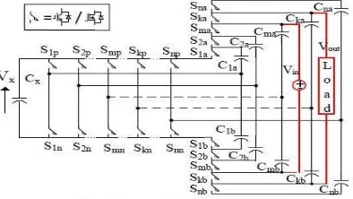
The (n/m) X converter is derived from a common structure of (k/m) X is shown in Fig.4. There are n arms and n legs in this converter which become total 2n limbs. Each arm has a series combination of two capacitors [45].
Fig.4 A generic (k/m) X Converter
2.3. Voltage Multiplier technique
400 V DC supply system gaining most popularity now days because of their higher efficiency, better reliability and most economically as compared to ac supply system [46]-[49]. Telecommunications, data communications, commercial and residential are the best example of dc distribution system [50]-[52]. In dc supply system or dc distribution systems, the most challenging task is dc-dc converters for 400 V systems. The range of PV panels is between 20 V to 40 V DC. For boosting up these voltages high duty ratio is required which results high voltage stress on components, voltage ripples and low efficiency. For overcome these drawbacks [53]-[56] have been proposed topologies for dc-dc boost converters followed by the voltage multiplier cells. Based on this technique Table I showing the comparison of different converters with respect to number of components, voltage gain and voltage stress on switches.
[image:3.595.302.534.436.617.2]Bin et. al [53] proposed a hybrid converter for high voltage gain but gives low output voltage as compared to its own VM circuit. It also has a large ripple in input current. Table 1 shows the comparison of different converters based on voltage gain and components used. The table has been formed using topologies presented in literatures [53]-[56].
Table 1: Comparison of different converters
Topology [53] [54] [55] [56] No of
Switches
1 1 2 2
No of Inductors
1 1 2 2
No of Capacitors
4 3 3 3
No of Diodes
4 3 3 4
Vout/Vin
Vswitch/v
out
(1-D)D
Input Current
Discont inuous
Contin uous
Discontin uous
Contin uous
[image:3.595.84.281.634.745.2]400 Dickson charge pump based voltage multiplier.
This converter is most useful for 400 V dc bus. This converter also has a tendency to extract power from both single source and two independent sources. Due to low voltage rating of capacitors for VM, these converters leads towards the size reduction.
2.4.Switched Inductor and Voltage Lift technique
For increasing the output voltage in dc-dc boost converter, voltage lift is one of better and approved method or technique. A capacitor is charged to a certain value by source voltage in this technique. After that the output voltage is boosted with voltage of charged capacitor. On adding more capacitor the voltage level can be increased more. When two capacitors are used, it is called re-lift, on three capacitors it become triple lift and similarly quadruple-lift technique [58]. Luo et. al [59] introduced some boost converters based on this technique. Zeta, Cuk and SEPIC converters have been used with Voltage Lift technique [60]. Fig.5 shows the basic structure of VL technique.
2.5.Magnetic Coupling
Magnetic coupling is most preferred boosting technique. It can be used as both non-isolated and
isolated dc-dc converter. There are some coupled- inductor based dc-dc converters have been designed to offer the freedom from the complexity of the switch duty cycle [61]-[68]. Due to leakage inductance of coupled inductor high voltage spikes occurs on device.
It also induces large energy losses. RCD snubbers can control the voltage variation or current and clamp voltage overshoot. RCD snubbers are composite of resistor, capacitor and diode. Leakage energy is still dissipated in this case so that these converters are also proposed [65]-[66]. In this case the number of switches increases which results the complexity in the circuit. Wai.et.al [67] proposed a passive regenerative snubber. This converter has higher voltage gain than others which are based on coupled inductor technology. In the same channel khalizadeh [68] et. al. proposed a converter with single switch by using three winding coupled inductor. Leakage energy of the inductor can be reused in this converter and also reverse recovery problem of diode can be reduced. This converter is designed for high voltage gain with high power density and efficiency. It consists of a single switch and two voltage multiplier cells. Besides this it is also have two regenerative snubbers for high voltage conversion, recycling the energy of stray inductance and reducing the voltage spike.
[image:4.595.70.511.90.237.2]3.
Comparison of Different Techniques
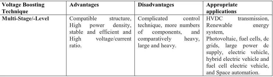
Table 2: Comparison of different techniques
Voltage Boosting Technique
Advantages Disadvantages Appropriate applications
Multi-Stage/-Level Compatible structure,
High power density, stable and efficient and High voltage/current ratio.
Complicated control technique, more numbers of components, and comparatively heavy, large and heavy.
HVDC transmission, Renewable energy system,
Photovoltaic, fuel cells, dc grids, large power dc supply, electric vehicle, hybrid electric vehicle and fuel cell electric vehicle, and Space automation. Co
VL-SL Cell
Do
Vo
[image:4.595.69.533.629.760.2]Vin S
Available online at www.ijrat.org
401 Switched Capacitor
(Charge Pump)
Cheap, Light weight, Small size, high power density and Fast response.
Comparatively
complicated modulation, Sensitive to the ESR of capacitors and Lack of output voltage regulation.
Energy accumulation, Mobile displays (AMOLED), Automotive and vehicular applications and High gain dc-dc applications.
Voltage Multiplier High voltage capability
topology, Cell based structure, and also it can be integrated to various converters.
High voltage stress on components, and need several cells for high voltage applications.
X-ray, laser, Military, plasma research and particle accelerator.
Switched Inductor and Voltage Lift
High boost ability, and
biddable in many
converters.
Need more passive elements, and not suitable for high power applications.
Mid-range dc-dc converters and High gain dc-dc applications.
Magnetic Coupling High design freedom,
Versatile in boost ability due to tunable, turns ratio of magnetic coupling, Switch can be implemented at the low voltage side help to reduce conduction losses and High efficiency in soft switched type.
Negative effects of leakage inductance, High voltage spike, and Relatively bulky.
High power/voltage DC supply, High voltage applications (military, physics), DC micro grids, Telecommunication and data centers, Bidirectional (FC, PV, UPS, P-EV, H-EV, V2G), Regenerative (elevator,
tram/trolleybus), and Avionic and space.
4. Conclusion
This paper presents a literature review of different
topologies of dc-dc converter which are discussed in
several international journals such as IEEE, IET, SCI
and many other international journals. These
converters were studied for better understanding about
converter techniques and their applications. This study
also gives the information about the best converter
topology with high voltage gain, less ripples, and high
efficiency. These converters have applications in solar
PV, electric vehicle and some other applications.
Many of these converters have been tested with
hardware and real time simulators. Also these are
tested with applications like solar and electric vehicle
etc.
REFERENCES
[1] M. Forouzesh, Y. P. Siwakoti, S. A. Gorji, F. Blaabjerg and B. Lehman, "A survey on voltage boosting techniques for step-up DC-DC converters," 2016 IEEE Energy Conversion
Congress and Exposition (ECCE), Milwaukee, WI, 2016, pp. 1-8.
[2] Revathi, B. S., &Prabhakar, M. (2016). Non isolated high gain DC-DC converter topologies
for PV applications–A comprehensive
review. Renewable and Sustainable Energy
Reviews, 66, 920-933.
[3] A. Ahmed, M. A. Khan, M. Badawy, Y. Sozer and I. Husain, "Performance analysis of bi-directional DC-DC converters for electric vehicles and charging infrastructure," 2013 IEEE Energy Conversion Congress and Exposition, Denver, CO, 2013, pp. 1401-1408.
[4] N. Mukherjee and D. Strickland, "Control of Cascaded DC–DC Converter-Based Hybrid Battery Energy Storage Systems—Part I: Stability Issue," in IEEE Transactions on Industrial Electronics, vol. 63, no. 4, pp. 2340-2349, April 2016.
[5] Kanchanaharuthai, A.; Chankong, V.; Loparo, K.A., "Transient Stability and Voltage Regulation in Multimachine Power Systems Vis-à-Vis STATCOM and Battery Energy Storage," IEEE Trans. Power Syst., vol.30, no.5, pp.2404-2416, Sept. 2015.
402 IET Renew. Power Gener, vol.7, no.5,
pp.531-539, Sept. 2013.
[7] Mithulananthan, N.; Shah, R.; Lee, K.Y., "Small-Disturbance Angle Stability Control With High Penetration of Renewable Generations," IEEE Trans. Power Syst., vol.29, no.3, pp.1463-1472, May 2014
[8] Ortega, A.; Milano, F., "Generalized Model of VSC-Based Energy Storage Systems for Transient Stability Analysis," IEEE Trans. Power Syst., vol. PP, no.99, pp.1-12, 2015 (in Press).
[9] Bazargan, D.; Filizadeh, S.; Gole, A.M., "Stability Analysis of Converter-Connected Battery Energy Storage Systems in the Grid," IEEE Trans. Sustain. Energy, vol.5, no.4, pp.1204-1212, Oct. 2014.
[10]Lu, X.; Sun, K.; Guerrero, J.M.; Vasquez, J.C.; Huang, L., "State-of-Charge Balance Using Adaptive Droop Control for Distributed Energy Storage Systems in DC Microgrid Applications," IEEE Trans. Ind. Electron., vol.61, no.6, pp.2804-2815, June 2014.
[11]Inthamoussou, F.A.; Pegueroles-Queralt, J.; Bianchi, F.D., "Control of a Supercapacitor Energy Storage System for Microgrid Applications," IEEE Trans. Energy Convers., vol.28, no.3, pp.690-697, Sept. 2013.
[12]Bostrom, A.; von Jouanne, A.; Brekken, T.K.A.; Yokochi, A., "Supercapacitor energy storage systems for voltage and power flow stabilization," in Proc. 1st IEEE Conf. on Technologies for Sustainability (SusTech), vol., no., pp.230-237, 1-2 Aug. 1-2013.
[13]Wandhare, R.G.; Agarwal, V., "Novel Stability Enhancing Control Strategy for Centralized PV-Grid Systems for Smart PV-Grid Applications," IEEE Trans. Smart Grid., vol.5, no.3, pp.1389-1396, May 2014.
[14]Kamel, R.M.; Chaouachi, A.; Nagasaka, K., "Three Control Strategies to Improve the Microgrid Transient Dynamic Response During Isolated Mode: A Comparative Study," IEEE Trans. Ind. Electron., vol.60, no.4, pp.1314-1322, April 2013.
[15]Massing, J.R.; Stefanello, M.; Grundling, H.A.; Pinheiro, H., "Adaptive Current Control for Grid-Connected Converters WithLCL Filter," IEEE Trans. Ind. Electron., vol.59, no.12, pp.4681-4693, Dec. 2012.
[16]Mohamed, Y. A -R I, "Mitigation of Converter-Grid Resonance, Converter-Grid-Induced Distortion, and Parametric Instabilities in Converter-Based Distributed Generation," IEEE Trans. Power Electron., vol.26, no.3, pp.983-996, March 2011. [17]Walker, G.R.; Sernia, P.C., "Cascaded DC-DC
converter connection of photovoltaic modules," IEEE Trans. Power Electron., vol.19, no.4, pp.1130-1139, July 2004
[18]Bratcu, A.I.; Munteanu, I.; Bacha, S.; Picault, D.; Raison, B., "Cascaded DC–DC Converter Photovoltaic Systems: Power Optimization Issues," IEEE Trans. Ind. Electron., vol.58, no.2, pp.403-411, Feb. 2011.
[19]Q. Wei, B. Wu, D. Xu and N. R. Zargari, "Model Predictive Control of Capacitor Voltage Balancing for Cascaded Modular DC–DC Converters," in IEEE Transactions on Power Electronics, vol. 32, no. 1, pp. 752-761, Jan. 2017.
[20]J. Yang, Z. He, H. Pang and G. Tang, "The Hybrid-Cascaded DC–DC Converters Suitable for HVdc Applications," in IEEE Transactions on Power Electronics, vol. 30, no. 10, pp. 5358-5363, Oct. 2015.
[21]G. Chen, Y. Deng, L.Chen, Y.Hu, L.Jiang, X. He, and Yousheng Wang, ―A Family of Zero-Voltage-Switching Magnetic Coupling Non-isolated Bidirectional DC-DC Converters, ― IEEE Trans. Ind. Electron., vol. 64, no. 8, pp. 6223 - 6233, Aug. 2017.
[22]M. R. Mohammadi , and H. Farzanehfard ,‖ Family of Soft Switching Bidirectional Converters with Extended ZVS Range,― IEEE Trans. Ind. Electron., vol. 64, no. 9, pp. 7000-7008, Sept. 2017.
[23]C. c. Lin , L. s. Yang , and G.W. Wu ,‖ Study of a non-isolated bidirectional DC-DC converter,― IET. Power Electron., vol. 6, no. 1, pp. 1755-4535, Jan. 2013.
[24]H. Ardi , R. R. Ahrabi , and S. N. Ravadanegh , ― Non-isolated bidirectional DC–DC converter analysis and implementation, ― IET. Power Electron., vol. 7, no. 12, pp. 3033 - 3044, Dec. 2014.
[25]H. Ardi , A. Ajami , F. Kardan , and S. N. Avilagh ,‖Analysis and Implementation of a Nonisolated Bidirectional DC–DC Converter With High Voltage Gain, ― IEEE Trans. Ind. Electron., vol. 63, no. 8, pp. 4878 - 4888, Aug. 2016.
[26]H. Bahrami, S. Farhangi, H. Iman-Eini and E. Adib, "A New Interleaved Coupled-Inductor Nonisolated Soft-Switching Bidirectional DC–DC Converter With High Voltage Gain Ratio," in IEEE Transactions on Industrial Electronics, vol. 65, no. 7, pp. 5529-5538, July 2018
[27]X. Hu and C. Gong, "A High Gain Input-Parallel Output-Series DC/DC Converter With Dual Coupled Inductors," in IEEE Transactions on Power Electronics, vol. 30, no. 3, pp. 1306-1317, March 2015.
Available online at www.ijrat.org
403 Transactions on Industrial Electronics, vol. 63,
no. 4, pp. 2190-2202, April 2016.
[29]V. A. K. Prabhala, P. Fajri, V. S. P. Gouribhatla, B. P. Baddipadiga and M. Ferdowsi, "A DC–DC Converter With High Voltage Gain and Two Input Boost Stages," in IEEE Transactions on Power Electronics, vol. 31, no. 6, pp. 4206-4215, June 2016.
[30]Y. Zhang, Y. Gao, J. Li and M. Sumner, "Interleaved Switched-Capacitor Bidirectional DC-DC Converter With Wide Voltage-Gain Range for Energy Storage Systems," in IEEE Transactions on Power Electronics, vol. 33, no. 5, pp. 3852-3869, May 2018.
[31]M. Bahrman and B. Johnson, ―The ABCs of HVDC transmission technologies,‖ IEEE Power and Energy Magazine, vol. 5, no. 2, pp. 32–44, 2007.
[32]N. Flourentzou, V. Agelidis, and G. Demetriades, ―VSC-based HVDC power transmission systems: an overview,‖ IEEE Trans. on Power Electron., vol. 24, no. 3, pp. 592–602, 2009.
[33]B. Gemmell, J. Dorn, D. Retzmann, and D. Soerangr, ―Prospects of multilevel VSC technologies for power transmission,‖ in Proc. IEEE Transmission and Distribution Conf. and Expo., pp. 1–16, 2008.
[34]S. Kouro, M. Malinowski, K. Gopakumar, J. Pou, L. Franquelo, B. Wu, J. Rodriguez, M. Perez, and J. Leon, ―Recent advances and industrial applications of multilevel converters,‖ IEEE Trans. on Ind. Electron., vol. 57, no. 8, pp. 2553– 2580, 2010.
[35]J. Candelaria and J.-D. Park, ―VSC-HVDC system protection: a review of current methods,‖ in Proc. IEEE Power Systems Conf. and Expo.,pp. 1–7, 2011.
[36]J. Yang, J. Zheng, G. Tang, and Z. He, ―Characteristics and recovery performance of VSC-HVDC transmission line fault,‖ in Proc. Asia Pacific Power and Energy Eng. Conf., pp. 1– 4, 2010.
[37]A. Lesnicar and R. Marquardt, ―An innovative modular multilevel converter topology suitable for a wide power range,‖ in Proc. IEEE Power Tech Conference, vol. 3, June 2003.
[38]E. C. Mathew, M. B. Ghat and A. Shukla, "A Generalized Cross-Connected Submodule Structure for Hybrid Multilevel Converters," in IEEE Transactions on Industry Applications, vol. 52, no. 4, pp. 3159-3170, July-Aug. 2016. [39]M. Das and V. Agarwal, "Design and Analysis of
a High-Efficiency DC–DC Converter With Soft Switching Capability for Renewable Energy Applications Requiring High Voltage Gain," in IEEE Transactions on Industrial Electronics, vol. 63, no. 5, pp. 2936-2944, May 2016.
[40]Singer, Z.; Emanuel, A.; Erlicki, M.S., "Power regulation by means of a switched capacitor," in Electrical Engineers, Proceedings of the Institution of , vol.119, no.2, pp.149-152, February 1972
[41]Singer, Z.; Emanuel, A.; Erlicki, M.S., "Power regulation by means of a switched capacitor," in Electrical Engineers, Proceedings of the Institution of , vol.119, no.2, pp.149-152, February 1972
[42]Tse, C.K.; Wong, S.C.; Chow, M.H.L., "On lossless switched-capacitor power converters," in Power Electronics, IEEE Transactions on , vol.10, no.3, pp.286-291, May 1995
[43]Makowski, M.S.; Maksimovic, D., "Performance limits of switched-capacitor DC-DC converters," in Power Electronics Specialists Conference, 1995. PESC '95 Record., 26th Annual IEEE , vol.2, no., pp.1215-1221 vol.2, 18-22 Jun 1995 [44]M. D. Seeman and S. R. Sanders, "Analysis and
Optimization of Switched-Capacitor DC-DC Converters," Computers in Power Electronics, 2006. COMPEL '06. IEEE Workshops on, Troy, NY, 2006, pp. 216-224.
[45]D. Gunasekaran, L. Qin, U. Karki, Y. Li and F. Z. Peng, "A Variable (n/m)X Switched Capacitor DC–DC Converter," in IEEE Transactions on Power Electronics, vol. 32, no. 8, pp. 6219-6235, Aug. 2017.
[46]V. A. K. Prabhala, B. P. Baddipadiga, and M. Ferdowsi, "DC distribution systems - An overview," in Renewable Energy Research and Application (ICRERA), 2014 International Conference on, 2014, pp. 307-312.
[47]G. AlLee and W. Tschudi, "Edison Redux: 380 Vdc Brings Reliability and Efficiency to Sustainable Data Centers," Power and Energy Magazine, IEEE, vol. 10, pp. 50-59, 2012. [48]V. Sithimolada and P. W. Sauer, "Facility-level
DC vs. typical ac distribution for data centers: A comparative reliability study," in TENCON 2010 - 2010 IEEE Region 10 Conference, 2010, pp. 2102-2107.
[49]S. M. Lisy, B. J. Sonnenberg, and J. Dolan, "Case study of deployment of 400V DC power with 400V/-48VDC conversion," in Telecommunications Energy Conference (INTELEC), 2014 IEEE 36th International, 2014, pp. 1-6.
[50]A. Fukui, T. Takeda, K. Hirose, and M. Yamasaki, "HVDC power distribution systems for telecom sites and data centers," in Power Electronics Conference (IPEC), 2010 International, 2010, pp. 874-880.
404 (INTELEC), 2011 IEEE 33rd International, 2011,
pp. 1-7.
[52]E. Rodriguez-Diaz, M. Savaghebi, J. C. Vasquez, and J. M. Guerrero, "An overview of low voltage DC distribution systems for residential applications," in Consumer Electronics - Berlin (ICCE-Berlin), 2015 IEEE 5th International Conference on, 2015, pp. 318-322.
[53]W. Bin, L. Shouxiang, L. Yao, and K. M. Smedley, "A New Hybrid Boosting Converter for Renewable Energy Applications," Power Electronics, IEEE Transactions on, vol. 31, pp. 1203-1215, 2016.
[54]W. Gang, R. Xinbo, and Y. Zhihong, "Nonisolated High Step-Up DC-DC Converters Adopting Switched-Capacitor Cell," Industrial Electronics, IEEE Transactions on, vol. 62, pp. 383-393, 2015.
[55]T. Yu, W. Ting, and H. Yaohua, "A Switched-Capacitor-Based Active-Network Converter With High Voltage Gain," Power Electronics, IEEE Transactions on, vol. 29, pp. 2959-2968, 2014. [56]J. C. Rosas-Caro, F. Mancilla-David, J. C.
Mayo-Maldonado, J. M. Gonzalez-Lopez, H. L. Torres-Espinosa, and J. E. Valdez-Resendiz, "A Transformer-less High-Gain Boost Converter With Input Current Ripple Cancelation at a Selectable Duty Cycle," Industrial Electronics, IEEE Transactions on, vol. 60, pp. 4492-4499, 2013.
[57]B. P. Baddipadiga and M. Ferdowsi, "A high-voltage-gain dc-dc converter based on modified dickson charge pump voltage multiplier," in IEEE Transactions on Power Electronics, vol. 32, no. 10, pp. 7707-7715, Oct. 2017.
[58]F. L. Luo and H. Ye, Advanced DC-DC Converters: crc Press, 2003.
[59] L. Fang Lin, "Luo-converters, voltage lift technique," in Proc. IEEE PESC, 1998, pp. 1783-1789 vol.2.
[60]E. H. Ismail, M. A. Al-Saffar, A. J. Sabzali, and A. A. Fardoun, "A family of single-switch PWM converters with high step-up conversion ratio,"
IEEE Trans. Cir. and Sys. I: Reg. Papers, vol. 55, pp. 1159-1171, 2008.
[61]W. H. Li and X. N. He, ― Review of non-isolated high step-up DC/DC converters in photovoltaic grid-connected applications,‖ IEEE Trans. Ind. Electron., vol. 58, no. 4, pp. 1239–1250, Apr. 2011.
[62]Y. P. Hsieh, J. F. Chen, T. J. Liang, and L. S. Yang, ―Analysis and implementation of a novel single-switch high step-up DC-DC converter,‖ IET Power Electronics, vol. 5, lss. 1, pp. 11-21, Jan. 2012.
[63]Tseng, Kuo-Ching, Jang-Ting Lin, and Chi-Chih Huang. "High step-up converter with three-winding coupled inductor for fuel cell energy
source applications." IEEE Transactions on Power Electronics, vol 30, no. 2: 574-581, 2015.
[64]X.F.Hu, G.R.Dai, L.Wang, C.Y.Gong, ―A Three-state switching boost converter mixed with magnetic coupling and voltage multiplier techniques for high gain conversion,‖ IEEE Transactions on Power Electronics, vol 31, no. 4: 2991-3001,2016.
[65]T. F. Wu, Y. S. Lai, J. C. Hung, and Y. M. Chen, ―Boost converter with coupled inductors and buck–boost type of active clamp,‖ IEEE Trans. Ind. Electron., vol. 55, no. 1, pp. 154-162, Jan. 2008.
[66]Y. Zhao, W. H. Li, and X. N. He, ―Single-phase improved active clamp coupled-inductor-based converter with extended voltage doubler cell,‖ IEEE Trans. Power Electron., vol. 27, no. 6, pp.2869-2878. Jun. 2012.
[67]R. J. Wai, and R. Y. Duan, ―High step-up converter with coupled-inductor,‖ IEEE Trans. Power Electron., vol. 20, no. 5, pp. 1025-1035, Sep. 2005.