2573
Constructal design of Array of Tree-shaped Heat Sink
1
R.Siddhardha,2P.V.Vinay,3M. Sumanth Sekhar 1
Assistant Professor, 2Professor , 3Student 1,2,3
Department of Mechanical Engineering,
GVP College for Degree and PG Courses, School of Engineering, Visakhapatnam, India
1
[email protected], [email protected], [email protected]
Abstract- An array of tree shaped heat sink is investigated and optimized by the constructal optimization method. In the first part of the paper a solid tree shaped heat sink was designed on the basis of conventional array of rectangular-fin heat sink, allocated volume as a constraint. In the second part, considering Fin material (volume fraction) as a constraint, an array of tree shaped heat sink with 3 stems was introduced. Experiments were conducted at constant heat input by varying Reynolds number from 15K to 40K.the center stem thickness (6mm) kept as constant and four different space to thickness ratios 1.5, 2, 2.75 and 4 (S/t) were considered for optimization.
Keywords -Tree-shaped Heat Sink, forced convection
1. INTRODUCTION
[1]Majed assumed a unidirectional conduction model with uniform heat transfer coefficient to analyze the thermal performance of the optimized tree-shaped fin by considering the space occupied, and material of the fin as constraints. The addition of more branches with equal length and thicknesses to the tree-shaped fin performs much better than longitudinal fin and the optimized T-shaped fins.[2] Bejan concentrated mainly on two aspects, the conductive and convective heat transfer over Constructal trees of circular fins. The geometry of the assembly is optimized to total volume, solid volume, number of circular fins, the external shape of the assembly, the optimal ratio of the central stem diameter to circular fin thickness, to minimize the thermal resistance and to maximize global conductance of the assembly. [3] They adopted triple optimization technique to optimize the constructal design i.e., Y-shaped assembly of fins, over the T-Y-shaped structure by varying length ratio, thickness ratio of root to stem of Y-shaped fin and also the angle between a tributary branch and the horizontal. The objective is to minimize the global thermal resistance. [4] they analyzed the pressure drop and heat transfer characteristics of a tree-shaped micro channel net and proposed certain advantages over conventional parallel channel nets such as more uniform temperature distribution and better stability in case of accidental blockage. [5] Giulio compared the performances of finned (straight fins) surfaces, using (CFD) software, with the reference of Bejan’s Constructal theory and found a valid agreement. [6] “The larger the number of freedom degrees for evolving is, the more perfect the system performance is”. (XIE ZhiHui, 2010).They studied the heat transfer performance of the twice Y-shaped assemblies over T-Y-shaped fin and Y-Y-shaped fin and found the corresponding constructal optimization
2574 has 15% lower thermal resistance and 26% smaller
material mass compared to the conventional heat sink. [16] Proposed wavy micro channel heat sink with porous fins having rectangular cross-section which reduces pressure drop by 43.0–47.9%, while thermal resistance increases by 4.1–4.9% .the increase in channel length accelerates the cooling mixing by Dean Vortices and forced diffusion. [17] Concentrated to improve the thermal performance of heat sink by mitigating the heat transfer stagnation zone, to achieve this the corner part of the heat sink was removed and placed the heat sink in vertical position.[18] Introduced fork-shaped inserts for better thermal performance. In this paper, an array of tree shaped heat sink is
investigated and optimized by the constructal optimization method. In the first part of this paper a solid tree shaped heat sink was designed on the basis of conventional array of rectangular-fin heat sink, volume as a constraint. In the second part, considering Fin material (volume fraction) as a constraint, an array of tree shaped heat sink with 3 branches was introduced. Experiments were conducted at constant heat input by varying inlet air velocities. Keeping the center array thickness (6mm) as constant, [9] The heat transfer enhancement occurs by adding material, by taking this as a consideration the array of tree shaped heat sink was optimized with four different space to thickness ratios 1.5, 2, 2.75 and 4 (S/t) respectively.
Nomenclature
Q Rate of heat transfer (W) Re Reynolds number
havg Average convective heat transfer coefficient (W/m2K) ν Kinematic viscosity As Total surface area (m
2
) Ac Cross sectional area (m
2 )
Ts Surface temperature (0C) P Perimeter (m)
Tout Outlet temperature (0C) St Stanton number
Tin Inlet temperature (
0
C) Pr Prandtl number
Nu Nusselt number Cf Coefficient of friction
K Thermal conductivity (W/mK) L Length of the reference block (m)
Dh Hydraulic diameter (m) B Breadth of the reference block (m)
U Velocity (m/s) H Height of the reference block (m)
2. MODEL
2.1. Array of rectangular fin heat sink
An array of rectangular-fin heat sink consists of 128 fins having 30mm length, 2.75 mm width, and 1.25 mm thickness over the base plate of thickness 4mm and area 36mmx 66mm made of Aluminium 6061 was taken from the CPU for reference. The volume occupied by the heat sink is 66mm x 36mm x 34mm.
2.2. Tree-shaped heat sink
A trunk of a tree acts like abridge network to connect the roots and other parts of it by thick-walled cells,to transfer water and nutrients. The basic idea of this model is to develop a heat sink which absorbs the heat from the source at the bottom and transfers to the branches through the trunk as shown in figure 1.
2575 Table 1: Dimensions of space and thickness.
By considering the volume (L x B x H) occupied by the reference model, a solid tree shaped heat sink was designed by Al-6061 as shown in Figure 3, to optimize the fin material, an array of tree shaped heat sink was introduced by varying space to thickness ratio in 4 stages. The dimensions of the tree shaped heat sink are as shown in Figure 2(b).and different space to thickness ratios are shown in Figure 2.
At 12mm space and 3mm thickness the model weighs same as reference heat sink. [9] As the tree-shaped assembly becomes better as the fraction of fin material increases. The thickness added in 1mm incremental in 4 stages up to 6mm by keeping the center stem thickness as constant.
2.3. Test sample preparation
[image:3.595.78.527.417.669.2]In EDM the machining process is in the form of die-sinking machines and wire-cutting machines (Wire EDM).The designed tree shaped heat sink was made by wire EDM process in which material was removed by a slowly moving wire travels along a prescribed path of the work piece.by using electro-thermal mechanism The material was removed in a sequence of discrete discharges between the wire electrode. The presence of dielectric fluid in the process creates a path for discharge as the fluid becomes ionized in the gap.
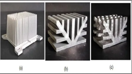
Fig. 2: Working models of (a) Array of rectangular fin heat sink, (b) Solid tree-shaped heat sink, (c) Array of tree-shaped heat sink
Space (mm) Thickness(mm) S/t
9 6 1.5
10 5 2
11 4 2.75
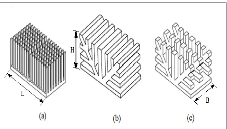
2576 Fig. 3: Dimensions of different models (a) Array of rectangular fin heat sink, (b) Array of tree heat sink,
.
[image:4.595.81.533.421.677.2]2577 2.4. Heat transfer and friction factor
The convective heat transfer rate
Q
conv conv from the electrically heated test surface is calculated usingconv electric cond
Q
Q
Q
(1)Where
Q
indicates the rate of heat transfer in which subscriptsrepresents the convection, electrical, and conduction, respectively. The electrical heatinput is calculated from the electrical potential and currentsupplied to the base plate. The conductive heat losses through the sidewalls can beneglected in comparison to those through the bottom surfaceof the test section. Using these findings, together withthe facts that the two side walls and the top wall of the testsection were well insulated and the readings of the thermocouple placed at the outer surface of the heating sectionwere nearly equal to the ambient temperature.The heat transfer from the test section by convection canbe expressed as
conv
2
out in
avg s s
T
T
Q
h
A
T
(2)Hence, the average convective heat transfer coefficient
avg
h
could be deduced viaconv
2
avg out in s sQ
h
T
T
A
T
(3)The total surface area is equal to the sum of theprojectedarea of the base plate and surface area contribution from the pin fins.
Total surface area (As) =Projected area of the base
plate + Total surface area contribution from the blocks
Nusselt number calculated based on the total surface area, will reflect the effectsof the variation in the surface area as well as the disturbances in the flow due to the fins on the heattransfer, in this study, the heat transfer enhancement characteristics were determinedby using Nu and Re based on.
avg
h
Nu
k
(4) hD U
Re
(5) 4 C h A D P (6)Where Dhis the hydraulic diameter of the duct, Ac is
the cross sectional area and P is the perimeter of the duct.
Reynolds’s analogygives a relation betweenthe momentum and heat transfer of the fluid flow. The dimensionless parameter Stanton number relates skin friction coefficient from Eqn. (8)
(7)
(8)
In all calculations, the values of the thermophysical propertiesof air were obtained at the bulk mean temperature, which is
T
m
T
in
T
out
/ 2
3. EXPERIMENTAL SETUP
The experimental setup consisting of the main duct test section and tested heat sinks as shown in fig .the internal cross section of the duct is 250 mm width and 150 mm height. The hydraulic diameter is 0.1875m.total length of the channel was 2.8 meter and the length of the test section is 400mm positioned horizontally.
2578 Fig 5: (1) Test section, (2) Variac, (3) Pressure transducers, (4) Anemometer, (5) Temperature indicator,
(6) Heat source, (7)Inlet, (8) Outlet, (9) Thermocouples, (10) Work piece.
[image:6.595.78.530.98.369.2]4. RESULT DISCUSSIONS
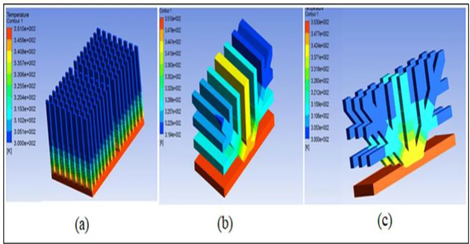
[image:6.595.73.545.457.702.2]2579 The Fig. 6 represents the temperature variation
along the heat sinks using FLUENT CFD solver. Here the sink receives heat from the chip which is placed at the bottom, located at the center of cross sectional area 30mmx30mm. So more temperature is observed at the bottom of the sink i.e. at the base plate. As shown in Figure 6(a) the temperature distribution is uniform for all fins. Fins localized at the center conduct a better amount of heat, where as in Figure 6(b) and 6(c) shows the importance of trunk part to distribute the temperature to the tips of the branches from the base. The difference in solid tree shaped heat sink to array of tree shaped heat sink is the former design fails to convect the heat from the center trunk to surroundings. But the later one distributes more uniformly without accumulating the heat.
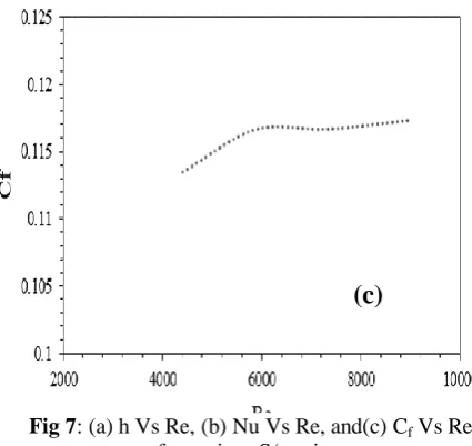
Fig. 7(a) shows Heat transfer co-efficient as a function of the Reynolds number based on hydraulic diameter, for different S/t ratios. As the velocity of the incoming air increases from 1.5m/s to 3m/s, as the Reynolds number increases the heat transfer coefficient also increases linearly, while considering different models, it was found that, at S/t ratio 2, i.e., 10mm space and 5mm stem thickness the thermal performance is significantly more than any other model. As mentioned earlier the tree-shaped assembly becomes better as the fraction of fin material increase it is also observed that the further increase in thickness contributes the rise internal thermal resistance to the heat sink and the trend is continued up to S/t is 0,i.e.,complete solid tree shaped heat sink. The trend of Nu number follows the same pattern as heat transfer co-efficient with respect to Reynolds number in figure 8(b) and there is no much variation in coefficient of friction with different air velocities can be shown in Fig. 7(c).
5. CONCLUSION
An array of tree shaped heat sink was investigated and optimized by the constructal optimization method. Fin material (volume fraction) as a constraint, an array of tree shaped heat sink with 3 stems was introduced. Experiments were conducted at constant heat input by varying Reynolds number, by keeping the center array thickness (6mm) as constant,though four different space to thickness ratios 1.5,2,2.75 and 4 (S/t),were considered, at 2 the thermal performance is significantly more.
Fig 7: (a) h Vs Re, (b) Nu Vs Re, and(c) Cf Vs Re for various S/t ratios.
(a)
(c)
[image:7.595.313.526.118.319.2] [image:7.595.55.289.303.743.2]2580 REFERENCES
[1] Almogbel, Majed A. "Constructal tree-shaped fins". International Journal of Thermal Sciences, vol. 44, pages 342–348, 2005.
[2] A. Alebrahim, A. Bejan, "Constructal trees of circular fins for conductive and convective heat transfer". International Journal of Heat and Mass Transfer, vol. 42, pages 3585-3597, 1999. [3] Giulio Lorenzini, Luiz Alberto Oliveira Rocha,
"Constructal design of Y-shaped assembly of fins". International Journal of Heat and Mass Transfer, vol. 49, pages 4552–4557, 2006. [4] Xiang-Qi Wang, Arun S. Mujumdar, Christopher
Yap, "Thermal characteristics of tree-shaped microchannel nets for cooling". International Journal of Thermal Sciences, vol. 45, pages 1103–1112, 2006.
[5] Giulio Lorenzini, Simone Moretti, "A CFD Application to Optimize T-Shaped Fins: Comparisons to the Constructal Theory’s Results". ASME, Journal of Electronic Packaging, vol. 129, pages 324-327, 2007. [6] XIE ZhiHui, CHEN LinGen & SUN FengRui,
"Constructal optimization of twice Y-shaped assemblies of fins by taking maximum thermal resistance minimization as objective". Science China technological Sciences, vol. 53, pages 2756–2764, 2010.
[7] XIAO QingHua, CHEN LinGen & SUN FengRui, "Constructal entransy dissipation rate minimization for umbrella-shaped assembly of cylindrical fins". Science China Technological Sciences, vol. 54, pages 211–219, 2011.
[8] Peng Xu, X.Q. Wang, A.S. Mujumdar, C. Yapa, B.M. Yu b, "Thermal characteristics of tree-shaped microchannel nets with/without loops" International Journal of Thermal Sciences, vol. 48, pages 2139–2147, 2009.
[9] Lingen Chen, Qinghua Xiao, ZhihuiXie, Fengrui Sun., "Constructal entransy dissipation rate minimization for tree-shaped assembly of fins". International Journal of Heat and Mass Transfer, vol. 67, pages 506–513, 2013.
[10] G. Lorenzini, C. Biserni, R.L. Correa, E.D. dos Santos, L.A. Isoldi, L.A.O. Rocha., "Constructal design of T-shaped assemblies of fins cooling a cylindrical solid body". International Journal of Thermal Sciences, vol. 83, pages 96-103, 2014. [11] G. Lorenzini, M. Medici, and L. A. O. Rocha,
"Convective Analysis of Constructal T-Shaped Fins". Journal of Engineering Thermophysics, vol. 23, pages 98–104, 2014.
[12] Kim, Dong-Kwon, "Thermal optimization of branched-fin heat sinks subject to a parallel flow". International Journal of Heat and Mass Transfer, vol. 77, pages 278–287, 2014.
[13] Dede, Ercan M., "Topology Optimization, Additive Layer Manufacturing, And Experimental Testing of An Air-Cooled Heat Sink," in ASME, San Francisco, California, 2015.
[14] C. Biserni, F.L. Dalpiaz, T.M. Fagundes, L.A.O. Rocha, "Constructal design of T-shaped morphing fins coupled with a trapezoidal basement: A numerical investigation by means of exhaustive search and genetic algorithm". International Journal of Heat and Mass Transfer, vol. 109, pages 73-81, 2017.
[15] Younghwan Joo, Ikjin Lee, Sung Jin Kim, "Topology optimization of heat sinks in natural convection considering the effect of shape-dependent heat transfer coefficient". International Journal of Heat and Mass Transfer, vol. 109, pages 123–133, 2017. [16] Gui Lu, Jun Zhao, Lin Lin, Xiao-Dong Wang ,
Wei-Mon Yan, "A new scheme for reducing pressure drop and thermal resistance simultaneously in microchannel heat sinks with wavy porous fins". International Journal of Heat and Mass Transfer, vol. 111, pages 1071– 1078, 2017.
[17] Xiangrui Meng, Jie Zhu , Xinli Wei, Yuying Yan, "Natural convection heat transfer of a straight-fin heat sink". International Journal of Heat and Mass Transfer, vol. 123, pages 561– 568, 2018.