217 | P a g e
EXPERIMENTAL INVESTIGATION OF THERMAL
CHARACTERISTICS WITH MULTIPLE TWISTED TAPE
INSERTS IN TUBULAR HEAT EXCHANGER
Chakole M.M.
1, Sali N.V.
2 1PG Student, Government college of Engineering, Karad, Maharashtra, (India)
2
Associate Professor, Government college of Engineering, Karad, Maharashtra, (India)
ABSTRACT
The aim of this present work is to enhance thermal performance characteristics in a tubular heat exchanger by studying
multiple twisted tapes in different arrangements. The tube inserted the multiple twisted tapes showed superior thermal
performance factor when compared with plain tube or the tube inserted a single twisted tape, due to continuous
multiple swirling flow and multi-longitudinal vortices flow along the test tube. The higher number of twisted tape
inserts led to an enhancement of thermal performance that resulted from increasing contact surface area, residence
time, swirl intensity and fluid mixing with multi-longitudinal vortices flow. Moreover, arrangement of twisted tapes in
counter current was superior energy saving devices for the practical use, particularly at low Reynolds number. This
was especially the case for quadruple counter tapes in the cross directions (CC-QTs) where heat transfer enhancement
with relatively low friction loss penalty was deserved. The use of CC-QTs led to the highest thermal performance factor
up to 1.33. The Nusselt number and friction factor increased to 2.28 times and 9.8 times of those in the plain tube.
Keywords:
Heat Transfer Enhancement, Dual/Triple/Quadruple Twisted Tapes, Multiple Swirl Flows, Heat Exchanger.I INTRODUCTION
Several heat transfer enhancement (HTE) techniques have been used in many engineering applications such as nuclear
reactor, chemical reactor, chemical process, automotive cooling, refrigeration, and heat exchanger, etc. HTE techniques
are powerful tools to increase heat transfer rate and thermal performance as well as to reduce of the size of heat transfer
system in installing and operating costs. HTE techniques can be classified into 2 categories; (1) active method: by
supplying external power source to the fluid or the equipment; (2) passive method: by turbulence promoter (such as
special surface geometries, twisted tape, propeller, tangential inlet nozzle, snail entry, axial/radial guide vane, spiral fin)
or fluid additives (such as nanofluid), without using any direct external power source. Due to its easy
installation/operation and cost saving, passive method has drawn great attention.
One important group of devices used in passive method is swirl flow devices which produce secondary recirculation on
the axial flow leading to an increase of tangential and radial turbulent fluctuation. This allows a greater mixing of fluid
inside a heat exchanger tube and subsequently reduces a thickness of the boundary layer [1]. Among the swirl generators
of tube inserts, twisted tapes have gained great attention and widely used for producing compact heat exchangers and
upgrading the heat transfer rate of the existing heat exchanger due to its low cost, acceptable thermal performance and
ease of manufacture installation [2]. Twisted tapes are generally equipped along the core tube to generate swirl causing
218 | P a g e
augmentation by improving flow velocities caused by partial blockage of the tube flow, which directs toward reducingthe hydrodynamic or thermal boundary layer thickness. The hydraulic diameter reduction results in greater heat transfer
coefficient, lengthening flow path in consequence of a helically twisting fluid motion, improving fluid mixing and
thinning thermal boundary layer. However, more pumping power is required when twisted tapes are equipped inside the
tube. Therefore, economic consideration has to be taken into account by using twisted tape with a proper geometry.
Nomenclature:
Greek SymbolA heat transfer surface area, m2 Tape thickness, m
D inside diameter of test tube, m η Thermal performance factor friction factor
h heat transfer coefficient, W m-2K-1 Abbreviations L length of test section, m
Nu Nusselt number ST single tape as single swirl flow generator
ΔP pressure drop, Pa Co-DTs dual co-tapes as co-dual swirl flow generators Pr Prandtl number C-DTs dual counter tapes as counter-dual swirl flow
Q Heat transfer rate, W generators
T Temperature, OC Co-TTs triple co-tapes as co-triple swirl flow generators W Tape width, m C-TTs triple co-tapes as counter -triple swirl flow
y Pitch length of twisted tape, m generators
y/W Twist ratio Co-QTs quadruple co-tapes as co-quadruple swirl flow generators
Subscripts CC-QTs quadruple counter tapes as counter-quadruple
swirl flow generators
b bulk PC-QTs quadruple counter tapes as parallel-quadruple
i inlet swirl flow generators
o outlet p plain tube t twisted tape w wall
II LITERATURE REVIEW
Since Whitham et al. [1] reported the success of using twisted tapes in improving heat transfer in heat exchanger, heat
transfer enhancement using the devices have been extensively studied. In particular, the modifications of twisted tape
have been continually released. Recently, many research groups modified various types of twisted tapes. They found
that the geometries of twisted tapes have significant influences on fluid mixing and heat transfer rate [3-6]. The modified
edges or centre of twisted tapes have been proposed to induce stronger turbulence intensity in the vicinity of tube wall
or the core of tube. Rahimi et al. [7] numerically evaluated heat transfer enhancement by modified twisted tapes
including jagged perforated and notch twisted tapes. Their results revealed that among the studied twisted tapes, jagged
twisted tape possessed the best performance with 31% higher heat transfer rate and 22% higher thermal performance
factor compared to those of typical twisted tape. Sivashanmugam and Suresh [8-11] compared the heat performance and
pressure drop of full length helical twisted and the helical twisted with spacer length in laminar and turbulent flow
region, and found that the tape with spacer length within 10% of the entire length could preserve heat transfer
augmentation and decrease pressure drop simultaneously. Krishna et al. [12] reported that the twisted tape with twist ratio
of 4 and width of 1 inch provided an appreciable heat transfer enhancement when space length was kept below 2 inches.
219 | P a g e
superior heat transfer enhancement to straight helical twist at the same twist ratio. Later, the helical and left-righttwisted tapes were used in thermosyphon solar water heating system to enhance heat transfer and thermal
performance [15]. Moreover, Nagarajan et al. [16] reported that the geometries of left-right twisted tapes played an
important role in governing heat transfer, friction factor and thermal performance. Jaisankar et al. [17] employed typical
twisted tapes with different twist ratios (3.0–5.0) in a solar water heater, and found that the tape with a smaller twist
ratio provided higher heat transfer enhancement as well as friction factor due to a stronger swirl flow intensity.
Eiamsa-ard et al. [18] investigated the effect of coupling twisted tapes on heat transfer enhancement in a heat exchanger.
The studied parameters were: (i) twisted tape orientation; co twisted tapes (co-CTTs) and counter twisted tapes
(counter-CTTs); (ii) width ratio; (iii) twist ratio. The experimental results revealed that heat transfer, friction loss and
thermal performance factor increased with decreasing twist ratio and increasing width ratio. Three different
arrangements were determined: (1) the wing-tips pointing upstream of the flow (TTW-up, twin delta-winged twisted
tape in counter-flow arrangement) (2) the wing-tips pointing downstream of the flow (TTW-down, twin delta-winged
twisted tape in co-flow arrangement) and (3) the wing-tips pointing opposite direction (TTW-o, opposite winged
twisted tape). At similar conditions, TTW-up gave the highest Nusselt number, friction factor and thermal performance
factor, followed by TTW-o and TTW-down. The TTW-up with wing-tip angle of 20° gave the maximum thermal
performance factor of 1.26 along with the Nusselt number and friction factor of 2.57 and 8.55 times compared to those
of the plain tube.
According to the above review, it has been proven that the heat transfer enhancement by using twisted tape is a
promising approach. However, the influences of the geometries of twisted tape on heat transfer enhancement, friction
factor and thermal performance characteristics and nanoparticles are limited explored. To extend the study in the field
of heat transfer enhancement by compound technique, this work introduces the use of modified twisted tapes (dual,
triple, quadruple twisted tapes) with water as base fluid. The study encompasses Reynolds number from 5000 to 25,000.
III DUAL/TRIPLE/QUADRUPLE TWISTED TAPES
The schematic view and details of the single, dual, triple and quadruple twisted tapes with different arrangements are
shown in Fig. 1(a &b) and Table 1. All twisted tapes were made of aluminium strip with a thickness of 0.8 mm, which
is a minimum twisting operation, and a length of 1000 mm. To fabricate a twisted tape, one end of a straight tape was
clamped while another end was carefully twisted to achieve a desired twist length. Single twisted tape was 19 mm in
width while dual, triple and quadruple twisted tapes were 8 mm in width. The tapes were formulated at constant twist
ratio (y/W) of 3 where twist ratio is defined as twist length (180°/twist length) to tape width (W). For dual, triple and
quadruple twisted tapes, each tape was individually twisted and subsequently welded together. In the experiment, the
swirl direction corresponding to tape arrangement was designed as: (i) co-swirl flow; all tapes were aligned to be
twisted in the same direction. In this case, dual, triple and quadruple twisted tapes were assigned as
Co-DTs/Co-TTs/Co-QTs, respectively, (ii) counter-swirl flow; this arrangement was designed for dual and quadruple twisted tapes.
In the case of dual twisted tapes, two tapes were aligned to be twisted in opposite directions and assigned as C-DTs. In
the case of quadruple twisted tapes, two tapes were aligned to be twisted in the same direction which was opposite to
that of other two tapes. In addition, the quadruple counter tapes consisting of two pairs of tapes were in two different
arrangements, to produce (1) parallel counter-swirl flow and (2) cross counter-swirl flow. For parallel counter-swirl
220 | P a g e
assigned as PC-QTs. For cross counter-swirl flow, the tapes in each pair produced swirl flow in the opposite directions.The quadruple counter tapes were assigned as CC-QTs.
Fig.1(a) Fig.1(b)
Table 1 Details of twisted tape inserts
Twisted tape ST Co-DTs C-DTs Co-TTs C-TTs Co-QTs PC-QTs CC-QTs
(a) Number of tape 1 2 2 3 3 4 4 4
(b) Tape width (W) 19 mm 8 mm 8 mm 7.5 mm 7.5 mm 7 mm 7 mm 7 mm (c) Tape pitch length
(y) 90 mm 40 mm 40 mm
37.5 mm
37.5
mm 35 mm 35 mm 35 mm (d) Twist ratio (y/W) 5 5 5 5 5 5 5 5 (e) Tape thickness (δ) 1 mm 1 mm 1 mm 1 mm 1 mm 1 mm 1 mm 1 mm
(f) Material Al Al Al Al Al Al Al Al
(g) Swirl type S–S Co D-Ss Counter
D-Ss Co T-Ss
Counter
D-Ss Co Q-Ss
Counter Q-Ss in P-A
Counter Q-Ss in C-A
IV EXPERIMENTAL STRATEGY
For this research work, the experimental setup fabricated is totally unique setup build for the investigation of performance of multiple twisted tape inserts. The different component of experimental setup are selected cautiously so that the component give the accurate performance. A specification of the present experimental setup is given in following table 2
Table 2 Specification of the Experimental Setup
Sr No Equipment Name Dimension Range / Capacity Remark
1 Test Section(Copper Tube) Length= 1m, ID= 18mm , OD= 23mm
2 Nichrome Wire Heater 3 kW, 20 Gauge, 240V, 5A Surface Temp=5500C
3 Insulation ( Ceramic wool) Thickness=20mm K=0.12 W/mk
4 Differential Manometer 0 to 500 mm Least Count= 1 mm
5 Pump 0.5HP
6 Thermocouple( K Type) 00C to 12600C Least Count= 0.10C
7 Rotameter 2 L/min to 20 L/min Least Count= 0.5 l/min
221 | P a g e
The experimental setup consists of a test section, a chiller, a storage tank, and a variable displacement pump with aby-pass valve arrangement, temperature indicator, flow meter and a differential manometer. The Schematic diagram of the
proposed experimental setup is shown in Fig2.
Fig2. Experimental Set-Up
Fig 2. Shows the photographic image of experimental setup fabricated for this dissertation. Test section consist of
copper tube of 1m length having 20mm and 23mm inside and outside diameter respectively. Nichrome wire is wound
on outer periphery of copper tube. Nichrome wire is properly insulated so that current will not pass to the copper tube
and other components. Several thermocouples are provided, in which two are used to record the inlet, outlet
temperatures of the working fluids and the remaining thermocouples are brazed on the outer periphery of the test
section of the tube, to measure the average surface temperature of the tube. Pressure drop across the test section is
measured by providing differential manometer. Copper tube along with Nichrome heater is thermally insulated to avoid
heat loss to the environment. Test section is covered with metallic sheet to protect it from physical damage. The aspect
ratio of the test section is sufficiently large for the flow to be hydro-dynamically developed.
The working fluid under investigation is forced through the test section with pump connected to the sufficient capacity
of storage tank. The fluid is heated by receiving heat from the test section and is allowed to cool by passing it through
an evaporative cooler. By recirculation, the chiller in the flow loop helps in achieving steady state condition faster. PUC
pipes are used to transfer of fluid. Flow meter is incorporated in order to measure flow rate of working fluid.
Temperature indicator with 0.10C least count is used to indicate temperature readings of various thermocouples
provided at different positions of test section. The physical properties of fluid flowing inside the tube of test section is
222 | P a g e
V RESULTS AND DISCUSSION
The experimental and numerical results of heat transfer enhancement by using dual, triple and quadruple twisted tapes
as tube inserts and water as the working fluids, are reported in this section. The results of the plain tube and the tube
with the single twisted tapes are also presented.
5.1 Verification of the plain tube with/without typical twisted tape
To gain confidence on experimental data throughout the research, the experimental data of the plain tube with water as
the working fluid were firstly compared with those from the open literatures [19] which are Dittus–Boelter and
Gnielinski correlations for Nusselt number and Blasius and Petukhov correlations for the friction factor.
Fig. 3 (a)
Fig. 3 (b)
Verification of the heat transfer and friction in the plain tube is shown in Fig. 3(a). The experimental Nusselt number
was in satisfactory agreement, the mean experimental Nusselt number of plain tube were respectively 9% and 12%
lower than that of the Dittus-Boelter and Gnielinski correlations. Experimental meanfriction factors of plain tube were
respectively 42% and 43% higher than that of the Blasius and Petukhov correlations. Fig. 3(b) shows the comparison
between the experimental data of the present plain tube equipped with the typical/single twisted tape and those from the
correlations of Manglik and Bergles[20]. Evidently, mean Nusselt number and friction factor of the tube with the
typical/single twisted tape (ST) were respectively 9.65% lower and 37.9% higher than those of Manglik and Bergles
equation. According to the comparative results mentioned above, it can be concluded that the present facility was
reliable and experimental data was accurate enough. These provide a strong confidence in the present investigation of
the heat transfer and flow friction in the tube equipped with dual/triple/quadruple twisted tapes.
Nusselt number correlations for the plain tube:
223 | P a g e
Correlation of Gnielinski:Friction factor correlation for the plain tube:
Correlation of Petukhov:
Correlation of Blasius
Nusselt number correlations for the typical twisted tape of Manglic and Bergles
Friction factor correlation for the typical twisted tape of Manglic and Borgles:
5.2 Effect of multiple twisted tapes
5.2.1 Heat transfer
224 | P a g e
number of swirl flows imparted to an axial flow, resulting in more uniform fluid mixing between the core
and the tube wall regions, throughout the tube.
Fig. 4 (a)
Fig. 4 (b)
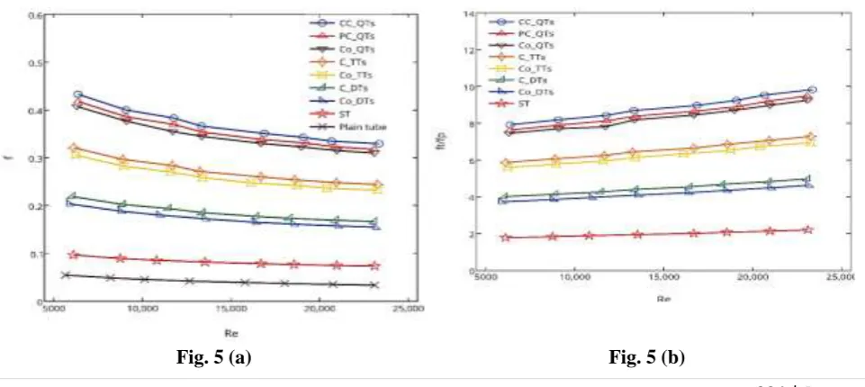
5.2.2. Friction loss
The friction loss of tubes equipped with tape inserts presented in terms of friction factor (ft) and friction factor ratio
(ft/fp), where fp is friction factor for the plain tube, is shown in 5. For all the cases, friction factor slightly decreased Fig.
5(a) while friction factor ratio (ft/fp) slightly increased Fig 5 (b) with increasing Reynolds number. The effect of twisted
tape on friction factor was found that friction factors generated in the tube with tape insert(s) were considerably higher
than those in the plain tube. In addition, multiple-tapes inserts (dual/triple/quadruple twisted tapes) consistently caused
higher friction factor than the single one. This is directly responsible by the larger surface area of the inserts which
perturbed the flows within the tubes. Moreover, an increase of swirl flow number boosted the interaction of the pressure
forces with inertial forces in the boundary layer. Therefore, the highest mean friction factors were observed in
quadruple twisted tapes. For co-swirl arrangement, friction factors over Co-QTs were 2.0 and 1.33 times higher than for
Co-DTs (co-dual twisted tapes) and triple twisted tapes, respectively. For counter-swirl arrangement, CC-QTs generated
1.96 and 1.34 times more friction factors than C-DTs (counter-dual twisted tapes) and C-TTs respectively. The
influence of multiple-tape inserts on friction factor ratio (ft/fp) was similar to that on friction factor (ft). The CC-QTs
gave the highest friction factor with the maximum friction factor ratio (ft/fp) of about 9.83.
225 | P a g e
5.2.3. Thermal performance factor
Fig. 6demonstrates the thermal performance factors (η) of tubes with tape inserts, which compromises between the heat
transfer and friction loss. For a net energy gain, the value of the thermal performance factor is greater than unity. The
results revealed that thermal performance factor decreased when Reynolds number increased. This implies the benefit
of using tape inserts at lower Reynolds number rather than at higher Reynolds number. For a given Reynolds number,
thermal performance factor increased as the number of tape inserts increased. It can be mentioned that the heat transfer
enhancement by tape inserted reflects an overwhelming of increased friction loss. The thermal performance factors of
the tubes with quadruple, triple and dual twisted tapes varied between 0.96-1.33, 0.82-1.13, and 0.77-1.01, respectively.
In other words, quadruple and triple twisted tapes respectively gave 13-27%, (-3)-8% higher thermal performance
factors than the single tape, whereas dual twisted tapes gave 4-10% lower thermal performance factors than the single
tape.
Fig 6
5.3. Effect of co-/counter tape arrangement
5.3.1. Heat transfer
The effect of co-/counter tape arrangement on heat transfer enhancement can be observed from Fig. 4 (a) and (b). The
tapes in counter arrangement consistently yielded higher Nusselt number than that in co-arrangement (Nu of
C-DTs > Nu of Co-C-DTs and Nu of CC-QTs and PC-QTs > Nu of Co-QTs). Nusselt number of C-C-DTs was 6.5-10.1%
higher than those of Co-DTs. For quadruple twisted tapes, Nusselt number of CC-QTs and PC-QTs was respectively
5.1-7.6% and 1.9–3.8% higher than those of Co-QTs. Comparing the heat transfer enhancement in counter arrangement
of QTs indicated that Nusselt number of CC-QTs was 5.6–3.7% higher than that of PC-QTs.
5.3.2. Friction loss
The effect of co-/counter tape arrangement on friction loss is shown Fig 5 (a) and (b). For dual twisted tapes, C-DTs
consistently caused higher friction factor than Co-DTs due to a higher Nusselt number reflecting to the pressure forces,
as similarly explained in Section 6.2.2. The friction factors of C-DTs were 7.5% higher than those of Co-DTs. That is,
the friction loss increased in the order CC-QTs > PC-QTs > Co-QTs. The friction factors of CC-QTs were 2.5% and
6.3% higher than those of PC-QTs and Co-QTs, respectively. In other words, friction factors of CC-QTs were 3.7%
226 | P a g e
5.3.3. Thermal performance factor
The effect of co-/counter tape arrangement on thermal performance factor at the same pumping power is shown in Fig.
6. Apparently, the tapes in counter arrangement possessed higher thermal performance factors than that in
co-arrangement. Therefore, it can be mentioned that in a case of DTs the heat transfer enhancement by C-DTs reflects an
overwhelming of increased friction loss. With a tubes equipped with QTs, the highest thermal performance of 1.33 was
observed for CC-QTs due to their excellent heat transfer enhancement with relatively low friction loss penalty. This
highlights the important role of CC-QTs in improving the performance. In addition, it can be noted that the counter tape
arrangement in all cases was superior energy saving devices for the practical use, particularly at low Reynolds number.
V CONCLUSIONS
The influences of multiple twisted tapes with a co- or counter arrangements (e.g., ST, Co-DTs, Co-TTs, Co-QTs,
C-DTs, PC-QTs, CC-QTs) and water as a working fluid on heat transfer enhancement are described in this study. The
experimental results are compared with the tube equipped with plain tube and typical twisted tape inserts. The
conclusions are drawn below:
Nusselt number, friction factor and thermal performance factor increased as a number of tapes increased. The tapes in counter arrangement provided higher thermal performance factor than that in co-arrangement,
Interestingly, CC-QTs exhibited superior twisted tape which delivers not only high Nusselt number but also
high thermal performance factor.
Over the range of Reynolds number 5000–25,000, Nusselt number in tubes with the Typical TT, Co-DTs,
C-DTs, Co-TTs,C-TTs, Co-QTs, PC-QTs and CC-QTs was, respectively, 20.6-31.7%, 30.4-35.3%, 38.8-49.0%,
60.7-70.1%, 66.5-77.8%, 91.9-112.9%,95.5-120.6%, 128.8-106.4%, higher than that of the plain tube. The
enhanced Nusselt number was accompanied with friction factors around 1.8-2.2, 3.7-4.6, 4-5, 5.6-6.9, 5.9-7.3,
7.4-9.3, 7.6-9.5, 7.9-9.8, times over that of the plain tube.
Thermal performance factors for Typical TT, Co-DTs, C-DTs, Co-TTs, C-TTs, Co-QTs, PC-QTs and
CC-QTs, were found to 0.96-1.33, 0.94-1.30, 0.92-1.26, 0.82-1.13, 0.82-1.08, 0.77-1.01, 0.75-0.98, 0.85-1.05,
respectively.
REFERENCES
[1]. J.M. Whitham, The effects of retarders in fire tubes of steam boilers, Str. Railw. J. 12 (1896) 374.
[2]. R.L. Webb, Performance evaluation criteria for use of enhanced heat transfer surfaces in heat exchanger
design, Int. J. Heat Mass Transf. 24 (1981) 715e726.
[3]. A.W. Date, U.N. Gaitonde, Development of correlations for predicting characteristics of laminar flow in a
tube fitted with regularly spaced twisted-tape elements, Exp. Therm. Fluid Sci. 3 (1990) 373-382.
[4]. S. Eiamsa-ard, C. Thianpong, P. Promvonge, Experimental investigation of heat transfer and flow friction in
a circular tube fitted with regularly spaced twisted elements, Int. Commun. Heat Mass Transf. 33 (2006)
1225-1233.
[5]. A.Dewan, P. Mahanta, K. SumithraRaju, P. Suresh Kumar, and Review of passive heat transfer
227 | P a g e
[6]. S. Eiamsa-ard, P. Seemawute, K. Wongcharee, Influences of peripherally-cut twisted tape insert on heattransfer and thermal performance characteristics in laminar and turbulent tube flows, Exp. Therm. Fluid Sci.
34 (2010)
[7]. M. Rahimi, S.R. Shabanian, A.A. Alsairafi, Experimental and CFD studies on heat transfer and friction
factor characteristics of a tube equipped with modified twisted tape inserts, Chem. Eng. Process. Process
Intensif. 48 (2009) 762-770.
[8]. P. Sivashanmugam, S. Suresh, Experimental studies on heat transfer and friction factor characteristics of
laminar flow through a circular tube fitted with helical screw-tape inserts, Appl. Therm. Eng. 26 (2006)
1990-1997.
[9]. P. Sivashanmugam, S. Suresh, Experimental studies on heat transfer and friction factor characteristics of
turbulent flow through a circular tube fitted with helical screw-tape inserts, Chem. Eng. Process. Process
Intensif. 46 (2007) 1292-1298.
[10].P. Sivashanmugam, S. Suresh, Experimental studies on heat transfer and friction factor characteristics of
laminar flow through a circular tube fitted with regularly spaced helical screw-tape inserts, Exp. Therm.
Fluid Sci. 31 (2007) 301-308.
[11].P. Sivashanmugam, S. Suresh, Experimental studies on heat transfer and friction factor characteristics of
turbulent flow through a circular tube fitted with regularly spaced helical screw-tape inserts, Appl. Therm.
Eng. 27 (2007) 1311-1319.
[12].S.R. Krishna, G. Pathipaka, P. Sivashanmugam, Heat transfer and pressure drop studies in a circular tube
fitted with straight full twist, Exp. Therm. Fluid Sci.33 (2009) 431e438.
[13].S.R. Krishna, G. Pathipaka, P. Sivashanmugam, Heat transfer and pressure drop studies in a circular tube
fitted with straight full twist, Exp. Therm. Fluid Sci. 33 (2009) 431-438.
[14].P. Sivashanmugam, P.K. Nagarajan, S. Suresh, Experimental studies on heat transfer and friction factor
characteristics in turbulent flow through a circular tube fitted with right-left helical screw-tape inserts, Chem.
Eng. Commun. 195 (2008) 977-987.
[15].S. Jaisankar, T.K. Radhakrishnan, K.N. Sheeba, Experimental studies on heat transfer and thermal
performance characteristics of thermosyphon solar water heating system with helical and left-right twisted
tapes, Energy Convers. Manag. 52 (2011) 2048-2055.
[16].P.K. Nagarajan, YagnaMukkamala, P. Sivashanmugam, Studies on heat transfer and friction factor
characteristics of turbulent flow through a micro finned tube fitted with left-right inserts, Appl. Therm. Eng.
30 (2010) 1666e1672.
[17].S. Jaisankar, T.K. Radhakrishnan, K.N. Sheeba, Experimental studies on heat transfer and friction factor
characteristics of thermosyphon solar water heater system fitted with spacer at the trailing edge of twisted
tapes, Appl. Therm. Eng. 29 (2009) 1224-1231.
[18].S. Eiamsa-ard, K. Nanan, C. Thianpong, P. Eiamsa-ard, Thermal performance evaluation of heat exchanger
tubes equipped with coupling twisted-tapes, Exp. Heat Transf. 26 (2013) 413-430.
[19].F.P. Incropera, P.D. DeWitt, T.L. Bergman, A.S. Lavine, Fundamentals of Heat and Mass Transfer,
John-Wiley & Sons, 2006.
[20].R.M. Manglik, A.E. Bergles, Heat transfer and pressure drop correlations for twisted-tape inserts in