Available Online atwww.ijcsmc.com
International Journal of Computer Science and Mobile Computing
A Monthly Journal of Computer Science and Information Technology
ISSN 2320–088X
IJCSMC, Vol. 4, Issue. 5, May 2015, pg.209 – 217
RESEARCH ARTICLE
Low Transmission Delay Based on
LEACH and PEGASIS Protocol in WSN
Hiba S. Mahdi
1, Imad J. Mohammed
2, Nushwan Y. Baithoon
31,2Department of Computers, College of Science, University of Baghdad, Baghdad, Iraq 3Department of Computers, College of Science for women, University of Baghdad, Baghdad, Iraq
[email protected] 1, [email protected] 2, [email protected] 3
Abstract - Wireless Sensor Networks (WSNs) are used to collect and send various kinds of messages to a base station, for instance, WSNs are used in many important applications such as health care, military and monitoring buildings. Routing protocol (such as LEACH and PEGASIS) is one of the important issues in WSN, when applying routing protocol on sensor nodes causes a delay in data transmission between sensor nodes and cluster head. This paper proposed a protocol named Enhanced PEGASIS protocol (EPEGASIS) based on clustering mechanism with k-means algorithm to compute the distances between sensor nodes and their own cluster head in each cluster. The EPEGASIS protocol achieves low transmission delay in wireless sensor networks. The simulation result shows that EPEGASIS protocol reduced the transmission delay between sensor nodes by about 27% compared with LEACH and by about 36% compared with PEGASIS protocols.
Keywords – Wireless Sensor Network (WSN), PEGASIS protocol, LEACH protocol, Transmission delay, K-means algorithm.
Introduction
sensor nodes are aggregated together and calculate the mean measurement mechanism. The target node is found based on the criteria such that the node which one is nearest to the base station in the range, and the energy level of the node is greater than the threshold level. This scheme effectively reduces the delay and save network energy compared to some of the previous schemes. These protocols highly useful in military based application, especially in cross border terrorisms for detecting an object. The detected events are quickly sending it to the base station for further actions [3].
The rest of the paper is organized in the following sections; a related work section which focuses on the existing developed techniques of transmission delay in WSN, followed by sections in which the structure of LEACH and PEGASIS protocols are discussed respectively. Then, the proposed method EPEGASIS is explained with four steps includes the k-means algorithm are given and how they deployed to satisfy the nodes clustering. Next, the performance evaluation of the EPEGASIS is discussed in details compared to LEACH and PEGASIS performances using two experiments. Finally, last section concludes the paper work.
Related Work
In 2003, Su Ping, study the special issue of time synchronization in tiny sensor networking devices and presents a Delay Measurement Time Synchronization (DMTS) technique applicable for both single hop and multi-hop wireless sensor networks. DMTS is flexible and lightweight in wireless sensor networks [4].
In 2009, Bo Jiang, introduce the concept of per-hop success probability to estimate the probability that a packet can reach the sink meeting its deadline and analyze the quantitative relation among the end-to-end delay, the probability of guaranteeing this delay, and network parameters for event-driven sensor networks [5].
In 2010, Joohwan K., Xiaojun L., Ness B.S. and Prasun S., they are interested in minimizing the delay and maximizing the lifetime of event-driven wireless sensor networks, for which events occur infrequently. The study of this paper is how to optimize the anycast forwarding schemes for minimizing the expected packet-delivery delays from the sensor nodes to the sink [6].
In 2012, Jiliang W., Wei D., Zhichao C. and Yunhao L., they are presented a comprehensive delay performance measurement and analysis in an operational large-scale urban wireless sensor network. We build a light-weight delay measurement system in such a network and present a robust method to calculate per-packet delay [7].
In 2014, Dinesh K. G. Proposed a new algorithm named “Distance-based Energy-Aware Routing” (DER) protocol. The proposed protocol that selects a route to the base station based on the mean measurement mechanism and a node, which is nearest to the base station within the range. The distance based energy aware routing efficiently reduces the time and energy in WSN [3].
Low Energy Adaptive Clustering Hierarchy (LEACH)
LEACH is a routing protocol in which the data are delivered to the data sink or base station in a cluster-based approach. There are a few factors to be kept in mind such as maximizing network lifetime, minimizing energy consumption and performing data processing at intermediate nodes to reduce the number of transmissions. It is a cluster-based hierarchy in which the entire network is divided into clusters and each cluster has a cluster head assigned to it. Cluster formation is dynamic in each round and the cluster head is responsible for the data collection from all the nodes of that cluster; it processes the data and sends the collected data to the base station. In LEACH, cluster heads are selected randomly, but the energy spent for each round is balanced as all the sensor nodes have a probability to be selected as a cluster head as shown in figure (1). For every round, 5% of the total sensor nodes are cluster heads [8].
1. The Cluster head is generated by a random method, so it cannot guarantee the even distribution of cluster heads, and the selection not considering the transmission distance and the node remains energy, leading the uneven energy consumption for different nodes.
Fig. 1 The structure of the LEACH protocol [9]
Power Efficient Gathering in Sensor Information System (PEGASIS)
PEGASIS is a chain based protocol provides improvement over LEACH algorithms. In PEGASIS, each node communicates only with a close neighbor and takes turns transmitting to the base station, thus reducing the amount of energy spent per round. Using greedy algorithm, the nodes are organized to form a chain, after that base station can compute this chain and broadcast it to all the sensor nodes. Energy saving in PEGASIS over LEACH takes place by many stages: First, in the local data gathering, the distances between the cluster head and the base station is less than the distances between each cluster head to the base station in LEACH. Second, only one node transmits to the base station in each round of communication as shown in figure (2). PEGASIS outperforms LEACH by limiting the number of transmissions, eliminating the overhead of dynamic [10].
Fig. 2 The structure of PEGASIS protocol [9]
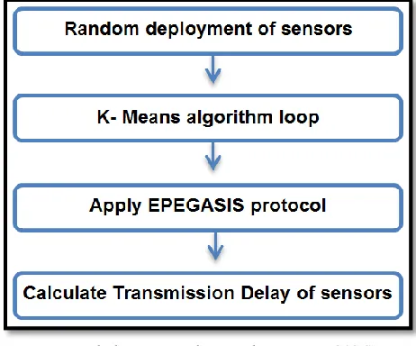
The structure of the proposed system consists of four main stages, as shown in figure (3). Each stage has specific functions. These four stages are:
Fig. 3 The structure of proposed system (EPEGASIS)
A. Random Deployment of Nodes
This stage defines and configures nodes randomly in the given topography, the number of all nodes is 100 (4 cluster head and 96 member nodes), network area is (500m×500m), the position of the base station is on the point (1650m, 700m) in x and y axis, this position is outside the network area.
B. K-means Algorithm Loop
K-means algorithm is one of the most popular clustering methods which are based on partitioning. It is very simple and fast algorithm for cluster head selection.
Step 1: Initial clustering
K-means algorithm is executed for cluster formation with the target WSN. Assume that the WSN of n nodes is divided into k clusters. First, k out of n nodes is randomly selected as the CHs. Each of the remaining nodes decides its CH nearest to it according to the Euclidean distance.
Step 2: Reclustering
After each of the nodes in the network is assigned to one of k clusters, the centroid of each cluster is calculated. With the new CH in each cluster, Step 2 is recursively executed until the CH is not changed anymore.
Step 3: Choosing the CH
After the clusters are formed, an ID number is assigned to each node of a cluster according to the distance from the centroid, assigning smaller numbers to the closer one [11].
C. Apply EPEGASIS Protocol
The data are transmitted from far node to the cluster head using the shortest path based on the Euclidean distance equation in K-means algorithm. It is characterized by the division of the network area into four colonies to reduce the transmission delay and to save the nodes energy besides the considering the shortest distances among the cluster heads themselves, such that the far cluster head transmitted the data to the nearest cluster head down to the base station. Our EPEGASIS protocol is characterized by local and global consideration in looking for a short distance between member nodes and cluster heads respectively.
D. Calculate Transmission Delay of Sensor Nodes
(Node_ID, Time and Energy) to the base station. Finally the base station calculates distance based on time and speed. The summarized data’s are broadcast it again to all nodes in the network by the base station.
The Equation for calculating the Distance:
D = S × T
Where, D is the distance between the node and the base station, S is the speed of waves in air and T is the time elapsed of a message to reach from the base station to the node [3].
Experimental Results
For our experiments, we simulate an environment with 100 sensor nodes in the field of size (500m × 500m) and the base station is located (1650m, 700m) at outside the wireless sensor area. We assume that sensor node has initial energy 0.5 joules. Therefore, the total initial energy of all nodes in the field is 50 joules. Many experiments have been done to evaluate the performance of the enhanced PEGASIS protocol using the clustering scheme and comparing the results with LEACH and PEGASIS protocols.
Experiment 1: (500m ×500m) Network Topology for Investigating the Transmission Delay
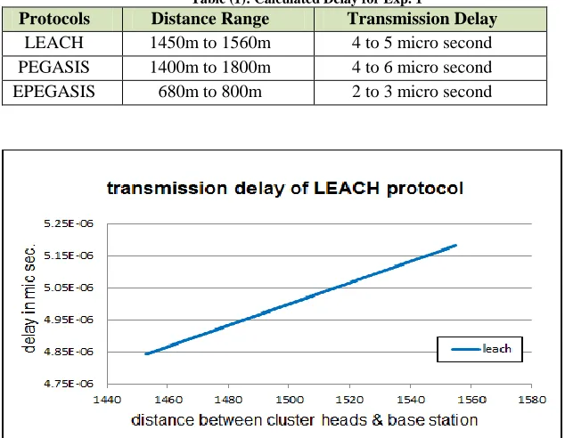
For this experiment, a set of tests for the transmission delay between cluster heads and the base station are calculated. Typically, in computer networks, there are many types of delay affecting the packet delivery to the destination such as processing delays, queuing delays, propagation delay and transmission delay. This experiment shows how the transmission delay (the significant parameter in WSN) impacts the performance of the proposed EPEGASIS compared to LEACH and PEGASIS routing protocols. Figure (4) shows the delay of LEACH protocol representing the calculated distance between the cluster heads to the base station directly. Thus, the average of the four distances from (CH1, CH2, CH3 and CH4) to the base station is calculated representing the delay transmission based on the speed equation. Numerically, using LEACH, the average of distances ranging from 1450m to 1560m and the transmission delay is 4 to 5micro second.
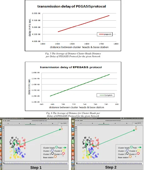
Comparatively, the result of transmission delay using LEACH protocol is better than the result of using PEGASIS protocol because the average of distances from four cluster heads to the base station using PEGASIS protocol is longer than the average distances using the LEACH protocol as shown in figure (5). In overall for PEGASIS, the average of distances ranges from 1400m to 1800m and the transmission delay is 4 to 6 microseconds.. Figure (6) shows the testing results of the transmission delay using EPEGASIS protocol. The distances between the cluster heads is less than the distances between them in the previous protocols which makes EPEGASIS the best in performance due to the decreased average of distances that range from 680m to 800m and the transmission delay is 2 to 3 microseconds. Table (1) summarizes experiment 1 results:
Table (1): Calculated Delay for Exp. 1
Protocols Distance Range Transmission Delay
Fig. 5 The Average of Distance Cluster Heads Distance per Delay of PEGASIS Protocol for the given Network
Fig. 6 The Average of Distance for Cluster Heads per Delay of EPEGASIS Protocol for the given Network
Cluster heads Path Cluster 1 Cluster 2 Cluster 3 Cluster 4 Base station
Step 1
Initialization of 100 nodes randomly in WSN
Cluster heads Path Cluster 1 Cluster 2 Cluster 3 Cluster 4 Base station
Step 2
Fig.7 EPEGASIS protocol using NAM of NS2
Figure (7) shows the necessary steps or screenshots produced from NAM/NS2. It explores how the cluster head is selected based on k-means algorithm through 100 nodes, deployed in (500m × 500m) area and divided into 4 clusters with 4 cluster heads. In step 1 of figure (7), the 100 nodes are divided into 4 clusters with four cluster heads; all are randomly distributed in the first round of simulation to initialize the system. The k-means algorithm is deployed to select the cluster heads based on Mean equation. From step 2 to step 6 the cluster heads are changed based on the computation of the Mean equation of k-means algorithm. The cluster heads consumed low energy and decrease the transmission delay.
Experiment 2: Comparing of LEACH, PEGASIS and EPAGASIS based on delay per round using (500m×500m) network topology
Experiment 2 investigates the transmission delay of (LEACH, PEGASIS and EPEGASIS) protocols related to the number of rounds figure (8). This test proves that, using simulation, the speed performance of LEACH protocol is better than PEGASIS protocol since normally the transmission delay represents the effect of distance and the transmission media. Analytically, using LEACH, the total distance between the member nodes and cluster head to the base station seems long, so the nodes consume more energy, but locally the transmission delay is less because the member nodes transmit their data to the cluster head directly which in turn sends the combined data to the base station directly within each colony. Using PEGASIS protocol and compared to LEACH, the total distance between the nodes and the cluster head down to the base station seems short; therefore the nodes consume less energy. But, the transmission delay of PEGASIS protocol is more comparable with LEACH protocol because the far node of the chain may take a longer distance in transmitting the data to its cluster head then to the base station within each colony.
Cluster heads Path Cluster 1 Cluster 2 Cluster 3 Cluster 4 Base station
Step 3
Cluster heads Path Cluster 1 Cluster 2 Cluster 3 Cluster 4 Base station
Step 4
Cluster heads Path Cluster 1 Cluster 2 Cluster 3 Cluster 4 Base station
Step 5
CH1, CH2, CH3 and CH4 are changed to new CHs
Cluster heads Path Cluster 1 Cluster 2 Cluster 3 Cluster 4 Base station
Step 6
on average. Moreover, using EPEGASIS, the nodes transmit the data to the cluster head, and then the cluster head sends data to the second cluster head down to the base station. That means that there are four colonies always worked together makes the balance or the distribution of energy consumption among cluster heads. As a result, EPEGASIS reduced the distance and transmission delay on average compared to the other tested protocols.
Fig.8 Transmission Delay for Routing Protocols per Rounds
Conclusion
Routing protocol is a very important area in wireless sensor network. The K-means algorithm applied clustering to the sensors node in order to decrease the transmission delay, in experiment one adopting 4 clusters using k-means algorithm is reduced the delay transmission compared with PEGASIS and LEACH, and avoiding the long chain in PEGASIS. When the distances between the nodes and cluster heads are short, the average of transmission delay to the base station becomes less. EPEGASIS protocol achieved the best result by decreasing the transmission delay compared with PEGASIS protocol by 27% and with LEACH protocol by 36%. In experiment two the proportion of improvement of EPEGASIS is very high comparing with LEACH and PEGASIS. The EPEGASIS still stable with low transmission delay. A long chain in PEGASIS causes some delay until round 72, PEGASIS outperforms LEACH until round 100, and EPEGASIS protocol with clustering achieved the minimum transmission delay compared with PEGASIS protocol by 48% and with LEACH protocol by 51%.
References
[1] L. Almazaydeh, E. Abdelfattah, M. Al- Bzoor, and A. Al- Rahayfeh,” Performance Evaluation of Routing Protocols in WSN”, International Journal of Computer Science and Information Technology, Volume 2, Number 2, April 2010.
[2] S. Zhong, G. Wang, X. Leng, X. Wang, L. Xue, Y. Gu, “A Low Energy Consumption Clustering Routing Protocol Based on K-Means”, Journal of Software Applications, 2012Engineering and, 5, 1013-1015.
[3] D. Kumar, “Distance-Based Energy-Aware Routing (DER) Protocol for Wireless Sensor Networks”, IJISET - International Journal of Innovative Science, Engineering & Technology, Vol. 1 Issue 6, August 2014.
[4] S. Ping, “Delay Measurement Time Synchronization for Wireless Sensor Networks”, Intel Research Berkeley Lab, IRB-TR-03-013 //June, 2003.
[6] J. Kim, X. Lin, N. B. Shroff, P. Sinha, “Minimizing Delay and Maximizing Lifetime for Wireless Sensor Networks With Anycast”, IEEE, 90/5446467/05339116. Apr 16, 2010.
[7] J. Wang, W. Dong, Z. Cao and Y. Liu, “On the Delay Performance Analysis in A Large-Scale Wireless Sensor Network”, [Online] www.greenorbs.org/people/jiliang/publications/rtss12-delay.pdf.
[8] P. Bansal, P. Kundu, and P. Kaur, “Comparison of LEACH and PEGASIS Hierarchical Routing Protocols in Wireless Sensor Networks”, Int. J. of Recent Trends in Engineering & Technology, Vol. 11, June 2014.
[9] G. Asha, S. Durgadevi, K. Shankar, “The comparison between routing protocols based on lifetime of wireless sensor networks”, International Journal of Engineering Science Invention, ISSN (Online): 2319 – 6734, ISSN, Volume 3 Issue 11 || November 2014 || PP.20-26.
[10] V. Kumar, S. Jain,and S. Tiwari, “Energy Efficient Clustering Algorithms in Wireless Sensor Networks: A Survey”, IJCSI International Journal of Computer Science Issues, Vol. 8, Issue 5, No 2, September 2011.
![Fig. 1 The structure of the LEACH protocol [9]](https://thumb-us.123doks.com/thumbv2/123dok_us/1950026.1256653/3.612.202.417.397.604/fig-structure-leach-protocol.webp)