Scholarship@Western
Scholarship@Western
Electronic Thesis and Dissertation Repository
11-19-2018 10:45 AM
The use of current steering during subthalamic deep brain
The use of current steering during subthalamic deep brain
stimulation to alleviate upper limb symptoms of Parkinson's
stimulation to alleviate upper limb symptoms of Parkinson's
disease
disease
Shabna Iftikar Mohideen The University of Western Ontario
Supervisor Jog, Mandar
The University of Western Ontario
Graduate Program in Physiology and Pharmacology
A thesis submitted in partial fulfillment of the requirements for the degree in Master of Science © Shabna Iftikar Mohideen 2018
Follow this and additional works at: https://ir.lib.uwo.ca/etd
Part of the Analytical, Diagnostic and Therapeutic Techniques and Equipment Commons, Nervous System Commons, Nervous System Diseases Commons, Neuroscience and Neurobiology Commons, Pharmacology Commons, and the Physiology Commons
Recommended Citation Recommended Citation
Iftikar Mohideen, Shabna, "The use of current steering during subthalamic deep brain stimulation to alleviate upper limb symptoms of Parkinson's disease" (2018). Electronic Thesis and Dissertation Repository. 5882.
https://ir.lib.uwo.ca/etd/5882
This Dissertation/Thesis is brought to you for free and open access by Scholarship@Western. It has been accepted for inclusion in Electronic Thesis and Dissertation Repository by an authorized administrator of
i
Subthalamic (STN) deep brain stimulation (DBS) is an established treatment to alleviate the appendicular motor symptoms of Parkinson's Disease (PD). Current steering during DBS allows the unequal fractionation of current between two electrodes on the lead, resulting in a non-spherical electrical field. It is hypothesized that the way the electrical field is shaped will affect a patient’s upper limb symptom alleviation. Seven PD patients who underwent
bilateral STN-DBS were tested over four weeks post-operation. 16 current fractionation settings were tested each week at an amplitude that increased weekly. Optimal setting was defined as the setting that provided the best symptom improvement based on kinematic data detected by a motion capture system and the Unified Parkinson's Disease Rating Scale. Results assessing right and left upper limb symptoms gave 14 optimal settings in seven patients, of which eight settings employed current steering either unilaterally or bilaterally, and six settings employed bilateral monopolar stimulation. Thus, the use of current steering was patient-dependent and limb-dependent; factors contributing to this finding include differences in lead placement, symptom heterogeneity, and possible differences in STN functionality.
Keywords
Parkinson’s disease, deep brain stimulation, current steering, motor symptoms, appendicular
ii
List of Abbreviations
BK: Bradykinesia BKI: Bradykinesia Index CT: Computed Tomography DBS: Deep Brain Stimulation
DSM: Diagnostic and Statistical Manual of Mental Disorders ED: Euclidean Distance
EEG: Electroencephalogram EMG: Electromyography FEF: Frontal Eye Field
fMRI: Functional Magnetic Resonance Imaging GABA: gamma-Aminobutyric Acid
GPe: Globus Pallidus Pars Externa GPi: Globus Pallidus Pars Interna HFS: High Frequency Stimulation IMU: Inertial Measurement Unit IPG: Implantable Pulse Generator LFP: Local Field Potential
M1: Primary Motor Cortex MER: Microelectrode Recording MRI: Magnetic Resonance Imaging OFF: Medication-off, Stimulation-off PD: Parkinson’s Disease
PFC: Prefrontal Cortex PMC: Premotor Cortex
PPN: Pedunculopontine Nuclei PSA: Posterior Subthalamic Area PT: Postural Tremor
RMS: Root-mean-square RRA: Retrorubral Area RT: Rest Tremor
iii SNc: Substantia Nigra Pars Compacta SNr: Substantia Nigra Pars Reticulata STD: Standard Deviation of the Signal STN: Subthalamic Nucleus
TSS: Tremor Severity Score TW: Therapeutic Window
UPDRS: Unified Parkinson’s Disease Rating Scale VIM: Ventral Intermediate Nucleus of the Thalamus VL: Ventral Lateral Thalamus
VLp: Ventral Posterolateral Nucleus of the Thalamus
iv
Co-Authorship Statement
Chapter 2
Methods of feature extraction (section 2.3.1) were computed by Mehdi Delrobaei and Sara Memar and adapted by Sima Soltani.
v
Acknowledgments
First off, I would like to thank my supervisor, Dr. Mandar Jog, for making this study possible; his dedication, optimism and perseverance helped me get through the pitfalls and minor mishaps along the way. Furthermore, his passion for research and commitment to advancing treatment has inspired some of my personal goals and strengthened my work ethic.
I would like to thank the members of my advisory committee, Dr. Stan Leung, Dr. Vania Prado and Dr. Arthur Brown, for their continued support and mentorship. They showed up to every meeting with an open mind and constructive criticism to help guide my work and make me a better scientist. A special thanks to Dr. Stan Leung for making time for me on
numerous occasions to provide feedback and a sense of direction.
I would like to thank the members of my lab, who went from awkward coworkers to friends who gave me laughs and the downtime I sometimes desperately needed. A special thanks to Sima Soltani, Daphne Hui, Greydon Gilmore and my volunteers for their time and effort in helping with data collection and analysis.
Lastly, I could not have made it this far without the unwavering support of my parents. Being there for me in every way with their (sometimes unsolicited) advice, words of encouragement and utmost love and care, I am truly grateful and feel indebted to them nearly as much as I feel indebted as a graduate student.
vi
Table of Contents
Abstract ... i
List of Abbreviations ... ii
Co-Authorship Statement... iv
Acknowledgments... v
Table of Contents ... vi
List of Tables ... ix
List of Figures ... x
List of Appendices ... xii
Chapter 1 ... 1
1 Introduction ... 1
1.1 Parkinson’s disease: overview and etiology ... 1
1.1.1 The classical model of basal ganglia function in PD ... 2
1.2 Deep brain stimulation for PD ... 5
1.2.1 Stimulation technology ... 6
1.2.2 Functional organization of the STN ... 6
1.2.3 Fundamentals of neuronal stimulation ... 8
1.2.4 Monopolar and multipolar stimulation ... 11
1.2.5 Current-based programming and current steering ... 11
1.3 STN-DBS procedure ... 16
1.3.1 Reasons for lead misplacement ... 16
1.4 Pathophysiology of bradykinesia ... 17
1.5 Pathophysiology of rigidity... 19
1.6 Pathophysiology of PD tremor... 20
vii
1.7.1 Summary of objectives ... 24
Chapter 2 ... 26
2 Methods ... 26
2.1 Study participants... 26
2.2 Assessment tools ... 27
2.2.1 Motion capture system ... 27
2.3 Clinical tasks and study timeline ... 28
2.3.1 Feature extraction... 32
2.4 Data analysis ... 34
2.4.1 Electrode localization... 36
Chapter 3 ... 37
3 Results ... 37
3.1 Study participants: clinical outcomes ... 37
3.2 Objective #1 results... 39
3.3 Objective #2 results... 55
Chapter 4 ... 67
4 Discussion ... 67
4.1 Discussion of objective #1 ... 67
4.1.1 Involvement of the ipsilateral STN ... 69
4.1.2 Lateralization of motor control ... 70
4.2 Discussion of objective #2 ... 71
4.2.1 Optimal tremor control ... 72
4.2.2 Optimal control of rigidity and bradykinesia ... 73
4.3 Implications and clinical relevance ... 74
4.4 Limitations ... 75
viii
4.6 Conclusion ... 76
Bibliography ... 77
Appendices ... 82
ix
List of Tables
Table 1: Participant pool demographics ... 27
Table 2: Current fractionation settings ... 32
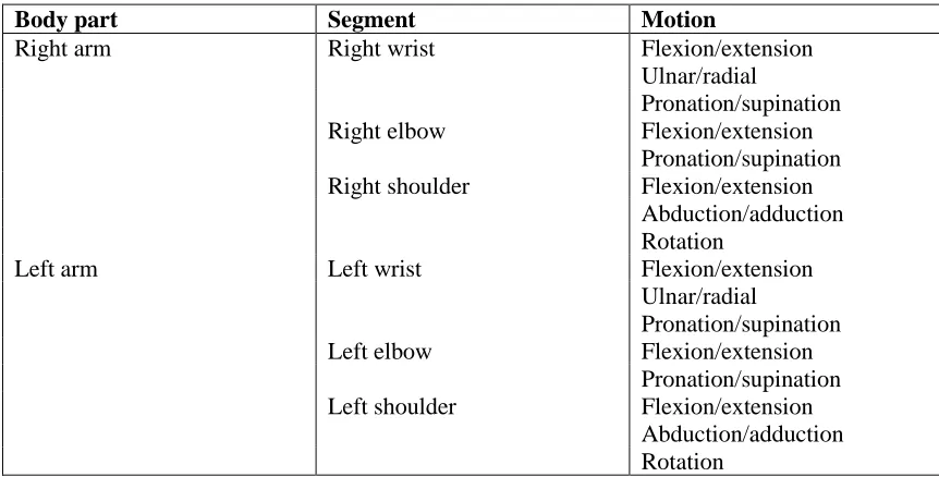
Table 3: List of joint angles for tremor assessment ... 34
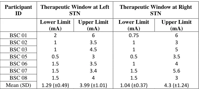
Table 4: Lower and upper amplitude limits of the therapeutic window ... 38
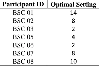
Table 5: Optimal setting at study conclusion according to whole-body UPDRS score ... 39
Table 6: Optimal settings for upper limb rest tremor, postural tremor and bradykinesia determined by kinematic data ... 54
Table 7: Week 1 optimal settings determined by UPDRS-III subscores ... 62
Table 8: Week 2 optimal settings determined by UPDRS-III subscores ... 63
Table 9: Week 3 optimal settings determined by UPDRS-III subscores ... 63
Table 10: Week 4 optimal settings determined by UPDRS-III subscores ... 64
Table 11: Chi-square assessment of instances involving settings that optimally alleviate hyperkinetic and hypokinetic symptoms in the same limb ... 65
Table 12: Chi-square assessment of instances involving settings that optimally alleviate only hyperkinetic symptoms in a limb ... 66
x
List of Figures
Figure 1: Schematic representation of the classical model of basal ganglia function in the (a)
normal and (b) parkinsonian states ... 3
Figure 2: Subthalamic Nucleus (STN) subdivision into three functional units; the sensorimotor, associative, and limbic regions ... 7
Figure 3: Altered electrical field shape using current steering ... 13
Figure 4: Dimmer-switch model of PD resting tremor ... 22
Figure 5: Position of IMU sensors on the upper limbs ... 28
Figure 6: Study timeline... 29
Figure 7: Optimal stimulation sites ... 37
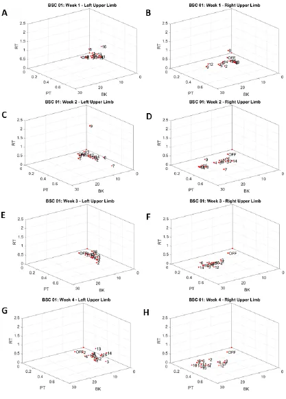
Figure 8: 3D graphs of kinematic data for BSC 01 ... 40
Figure 9: 3D graphs of kinematic data for BSC 02 ... 42
Figure 10: 3D graphs of kinematic data for BSC 03 ... 44
Figure 11: 3D graphs of kinematic data for BSC 05 ... 46
Figure 12: 3D graphs of kinematic data for BSC 06 ... 48
Figure 13: 3D graphs of kinematic data for BSC 07 ... 50
Figure 14: 3D graphs of kinematic data for BSC 08 ... 52
Figure 15: Euclidean distances (EDs) of optimal settings for alleviation of rest tremor, postural tremor and bradykinesia in the left and right upper limbs of patients with Parkinson's disease ... 54
Figure 16: Radar charts of UPDRS-III subscores for BSC 01 ... 55
xi
Figure 18: Radar charts of UPDRS-III subscores for BSC 03 ... 57
Figure 19: Radar charts of UPDRS-III subscores for BSC 05 ... 58
Figure 20: Radar charts of UPDRS-III subscores for BSC 06 ... 59
Figure 21: Radar charts of UPDRS-III subscores for BSC 07 ... 60
xii
List of Appendices
Appendix 1: Letter of Information and Consent ... 82
Appendix 2: Ethics Approval Notice ... 94
Appendix 3: Unified Parkinson's Disease Rating Scale Part 3 ... 95
Appendix 4: Electrode Localization ………...…99
Chapter 1
1
Introduction
The current thesis investigates the effects of current steering during deep brain stimulation of the subthalamic nucleus on the appendicular motor symptoms of Parkinson’s disease. This chapter lays down the foundation of Parkinson’s disease,
exploring its etiology and the available treatment. An in-depth review on deep brain stimulation will be presented, focusing on different targets in the brain and the technology used for stimulation. Next, the pathophysiology of the three main
appendicular motor symptoms—bradykinesia, tremor, and rigidity—will be detailed, followed by the study rationale and objectives.
1.1 Parkinson’s disease: overview and etiology
Parkinson’s disease (PD) was first medically described by James Parkinson in 1817 in his short monograph “An Essay on the Shaking Palsy” (Parkinson 1817). It is a progressive
neurodegenerative disease characterized by motor and non-motor symptoms (DeMaagd & Philip, 2015). The cardinal motor features include resting tremor, muscular rigidity, and bradykinesia, which are often reported as the first clinical findings of the disease (DeMaagd & Philip, 2015). Although the cardinal features mainly affect the appendages of the body, PD also includes axial symptoms such as dysarthria, gait dysfunction, and postural instability (Bejjani et al., 2000). Nonmotor presentations of the disease have been stated to occur before the onset of motor symptoms and include sleep disorders, depression, and cognitive changes (DeMaagd & Philip, 2015).
PD is one of the most common neurodegenerative diseases, with an incidence in the U.S. of approximately 60,000 cases per year and a prevalence of approximately 1% in people 60 years of age and older (DeMaagd & Philip, 2015). With the mean age of onset close to 60 years, PD is primarily a disease of the elderly although individuals have developed the disease as early as their 30s. There are gender differences in the incidence of PD,
The pathophysiological hallmark of PD can be characterized by two processes: (a) the loss of dopaminergic neurons in the pars compacta of the substantia nigra (SNc); (b) the presence of Lewy bodies, composed of α-synuclein, which become misfolded and accumulate in surviving neurons of the SNc and other brain regions (Connolly & Lang, 2014). There is 30-70% cell loss in the SNc when motor symptoms of PD become
evident (Rizek, Kumar, & Jog, 2016). Dopamine deficiency is said to be the predominant neurochemical abnormality, with the involvement of nondopaminergic brain regions as the disease progresses (Connolly & Lang, 2014). Cognitive dysfunction, mood disorders and impulse control disorders observed in PD patients are related to a dopamine
deficiency outside the basal ganglia or in serotonergic and noradrenergic systems (Rizek et al., 2016).
1.1.1 The classical model of basal ganglia function in PD
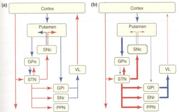
GPi/SNr (Obeso et al., 2000). Thus, the direct and indirect pathways have opposing effects on basal ganglia output with the activation of neurons in the direct pathway facilitating motor activity, and activation of the indirect pathway suppressing motor activity (Obeso et al., 2000). In a normal brain, the model proposes that dopamine from the SNc exerts a dual effect on striatal neurons by exciting D1-receptor-expressing neurons in the direct pathway and inhibiting D2-receptor-expressing neurons in the indirect pathway (Obeso et al., 2000). In PD, dopamine deficiency causes increased activity in the indirect circuit and reduced activity in the direct circuit. Although an oversimplification, the imbalance between the direct and indirect striatal pathways partly provides an explanation for the cardinal symptoms of PD. A schematic representation of the classical model of basal ganglia function in the normal and parkinsonian state is shown below (Figure 1; Obeso et al., 2000).
© Elsevier. Adapted with permission.
Figure 1: Schematic representation of the classical model of basal ganglia function in the (a) normal and (b) parkinsonian states
Blue arrows depict inhibitory projections and red arrows depict excitatory projections; thickness of arrow signifies the degree of activation. Direct pathway connects the putamen with the output nuclei (globus pallidus pars interna (GPi) and substantia nigra pars reticulata (SNr)) directly and the indirect pathway contains synaptic connections in the globus pallidus pars externa (GPe) and subthalamic nucleus (STN). (a) In the normal state, dopamine inhibits neuronal activity in the indirect pathway and excites neurons in the direct pathway. (b) In PD, dopamine depletion leads to disinhibition of striatal neurons in the indirect pathway, leading to increased inhibition of the GPe and
neurons and overinhibition of thalamo-cortical motor centers. SNc: substantia nigra pars compacta; PPN: pedunculopontine nuclei; VL: ventral lateral thalamus.
The goal of therapy aims to replace dopamine with dopaminergic medications to
modulate the dysfunctional circuit in the basal ganglia. Although there is no established cure or disease-modifying therapies (Connolly & Lang, 2014), there are treatments to improve the quality of life for PD patients. There is strong evidence to support the use of levodopa and dopamine agonists at all stages of PD to treat motor symptoms, levodopa being the most effective medication (Connolly & Lang, 2014). Levodopa is transported from the peripheral circulation across the blood-brain barrier and is converted to
dopamine in the striatum where it exerts its dopaminergic effects. Although levodopa is prescribed to treat almost all motor symptoms, its adverse effects can hinder the
symptomatic benefit gained by patients. The adverse effects of levodopa include nausea, orthostatic hypotension, hallucinations and motor complications such as motor
fluctuations and dyskinesia (Connolly & Lang, 2014). Motor fluctuations are alterations between “on” and “off” periods; on periods are when patients experience a good response to medication and off periods are when the benefit from medication wears off and
symptoms re-emerge (Connolly & Lang, 2014). Dyskinesia is defined as involuntary movements correlated to fluctuations in dopamine levels and can lead to impaired motor function and injury. Motor fluctuations are unexpected variations in the motor response to dopaminergic therapy whereas dyskinesias are unwanted and intrusive movements caused by levodopa (Rizek et al., 2016). In 40%-50% of patients, motor fluctuations and dyskinesias will develop within five years of chronic levodopa treatment and after 10 years of levodopa treatment in 70%-80% of patients (Rizek et al., 2016). Catechol O-methyltransferase (COMT) inhibitors, monoamine oxidase B inhibitors and dopamine agonists may be prescribed to reduce off periods. Reduction of dopaminergic medication can reduce the severity of dyskinesia; however, this will cause re-emergence of PD symptoms. For this reason, medications such as Amantadine, an antiviral with
concentration, causing the efficacy of levodopa to decline due to the emergence of
dyskinesia and motor fluctuations (Rizek et al., 2016). As a result, many PD patients look to neurosurgical interventions for managing their symptoms. The classical model of basal ganglia function and its prediction of increased STN and GPi activity in PD can be used to justify the efficacy of targeting these two nuclei with deep brain stimulation (DBS), which represents the gold standard of treatment for motor fluctuations and dyskinesia in advanced PD (Magrinelli et al., 2016).
1.2 Deep brain stimulation for PD
DBS is widely accepted as a treatment option for PD, dystonia, tremor, and is less known as a treatment for many other movement disorders (Fasano & Lozano, 2015). For PD, a consistent and sustained improvement in motor function and quality of life can be achieved through DBS (Fasano & Lozano, 2015). DBS works by sending an electrical current through a set of electrodes attached to a lead; the lead is placed within a target region—which differs according to the diagnosis—inside the brain. The lead is attached to the pulse generator, implanted in the chest region, through a wire that runs
subcutaneously. Candidates for DBS to treat PD require a disease duration of at least 5 years and clear and significant response to levodopa is considered as a favorable predictor for surgery (Broggi, Franzini, Marras, Romito, & Albanese, 2003). Other inclusion criteria include: (1) idiopathic PD, (2) stage II or IV on the Hoehn-Yahr scale (rates the severity of PD in five levels, with I being the mildest), (3) severe motor fluctuations, (4) no dementia or psychiatric abnormalities (Broggi et al., 2003).
and axial motor symptoms respond better to GPi stimulation (Fasano & Lozano, 2015). Specifically, studies have pointed towards favoring STN stimulation for rigidity and bradykinesia, although no difference between targets was seen for tremor (Fasano & Lozano, 2015). Dyskinesia suppression and long-term effects on stability and cognition favor GPi (Fasano & Lozano, 2015). Because the long-term outcome is better known for STN DBS, it is viewed by many as the ultimate therapy targeting advanced stages of PD (Romanelli, Bronte-Stewart, Heit, Schaal, & Esposito, 2004).
1.2.1 Stimulation technology
The first commercially available DBS system was manufactured by Medtronic in 1976 (Kopell, Machado, & Butson, 2009). Since then, DBS therapy has come a long way with constant modifications to the implantable pulse generator (IPG) and lead that make up the neurostimulation system. IPGs can be programmed for adjustments in current amplitude, pulse width, and frequency, as well as for the activation of individual contacts on the lead as cathodes or anodes. IPGs were initially limited in frequency output to 185 Hz and pulse widths longer than 500 µs are rarely used (Kopell et al., 2009). The stimulation amplitude ranges from 0 to 25 mA in different devices (Kopell et al., 2009). In PD, most clinical DBS studies have found frequencies in the range of 143 to 173 Hz, pulse widths in the range of 67 to 138 µs, and amplitudes in the range of 2.4 to 4.4 V effective in controlling motor symptoms (Wagle Shukla, Zeilman, Fernandez, Bajwa, & Mehanna, 2017). Before discussing the difference between voltage-controlled systems and current-controlled systems, as well as monopolar and multipolar stimulation, a better
understanding of the mechanisms underlying the therapeutic effects of DBS can be achieved by investigating the functional organization of the STN.
1.2.2 Functional organization of the STN
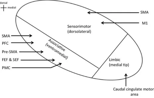
Kaplitt, & Lozano, 2004). A similar functional subdivision has been applied to the STN based on cortical projections (Tewari et al., 2016). The dorsolateral STN contains the sensorimotor region; direct projections from the primary motor cortex and supplementary motor area (SMA) are received here. The ventromedial STN contains the associative region with projections from the premotor cortex, prefrontal cortex, pre-SMA, SMA, frontal eye field, and supplementary eye field (Tewari et al., 2016). The limbic region is located in the medial tip of the STN, receiving projections from the caudal cingulate motor area (Figure 2; Tewari et al., 2016).
© Frontiers Media. Adapted with permission.
Figure 2: Subthalamic Nucleus (STN) subdivision into three functional units; the sensorimotor, associative, and limbic regions
Cortical inputs into each region depicted by individual arrows. SMA: supplementary motor area; M1: primary motor cortex; PFC: prefrontal cortex; FEF: frontal eye field; SEF: supplementary eye field; PMC: premotor cortex.
The purpose of investigating the functional organization of the STN is to determine if there is an optimal stimulation site for DBS. There is evidence to show that the
dorsolateral STN border is included in the optimal stimulation site – which is valid since the dorsolateral portion is the sensorimotor region with inputs from motor cortical areas. Included in the evidence pointing towards this conclusion is a study by Herzog and his colleagues who evaluated the optimal stimulate site in 14 patients treated by bilateral STN-DBS (Herzog et al., 2004). The position of the most effective contact on a
(Herzog et al., 2004). The best clinical results with the least energy consumption were found in contacts located in the dorsolateral border zone, whereas contacts within the STN white matter were significantly less effective (Herzog et al., 2004). Although the study does not provide a mechanism for DBS, it reinforces the relevance of the
neighboring structures at the dorsolateral STN boundary in alleviating parkinsonian symptoms (Herzog et al., 2004).
1.2.3 Fundamentals of neuronal stimulation
Defining the response of the neural elements, near the site of the electrode, to the applied electric field can contribute to the understanding of the effects of DBS. The DBS electric field is a three-dimensionally complex phenomenon that is generated by the redistribution of charged ions in the extracellular space of neurons (McIntyre & Anderson, 2016). Since the 1960s, an upheld view was that the primary effect of electrical stimulation in the brain was the generation of action potentials. The action potential is a change in the electrical potential across the neuronal membrane caused by the flow of electrical charges
(Montgomery Jr., 2017). DBS works by depolarizing the neural membrane to reach the activation threshold for action potential generation. The axon of a neuron has the lowest threshold for activation; therefore DBS exerts its effects in the axon at the
electrical stimulation can spread to affect neural elements outside of the immediate nucleus being stimulated, one might argue that STN or GPi stimulation is a way of labeling where the electrodes are placed to deliver electrical pulses as opposed to using it as a convention for the stimulation of a specific nucleus. Although there is evidence to show the neuronal responses to DBS, insight into the therapeutic mechanisms and specifically, why targets such as the STN and GPi provide clinical benefit remains unclear. A growing number of studies have been conducted to investigate whether the therapeutic action of DBS is an excitatory or inhibitory nervous system response.
1.2.3.1 Does DBS elicit an inhibitory or excitatory response?
Although evidence points to DBS pulses causing the generation of action potentials in axons near the electrode, other theories argue in favour of reduced neuronal firing. Due to the observation of similar clinical effects, it is possible that DBS and surgical lesions share a similar mechanism of action through the inhibition of neuronal activity (Laxton et al., 2009). One potential way of carrying out neuronal inhibition is through the alteration of cellular and membrane properties by the application of high frequency stimulation (HFS) (Laxton et al., 2009). An in vitro study found that HFS decreases the excitability of neurons in the rat STN through inactivation of voltage-gated sodium and calcium currents (Beurrier, Bioulac, Audin, & Hammond, 2001). Therefore, HFS shows the ability to block depolarization by transiently depressing calcium channels (Beurrier et al., 2001). Another study showed that HFS causes increased extracellular potassium levels in rat hippocampal slices (Bikson et al., 2001). These elevated potassium levels depolarize the neuron to produce a depolarization block. Persistent membrane depolarization induces this depolarization block, which results in the inactivation of voltage-gated sodium channels and by extension, prevents action potentials (Bikson et al., 2001). The application of in vitro findings to the understanding of DBS effects is somewhat trivial due to the fact that current densities in animal studies are much higher than those used in human DBS and the slice preparations lack many of the connections and pathological activity patterns that exist in human PD patients (Laxton et al., 2009).
stimulation site (Filali, Hutchison, Palter, Lozano, & Dostrovsky, 2004). Furthermore, another study showed that low frequency microstimulation (5 Hz) within the GPi caused inhibition of GPi neurons lasting a duration of 10-25 ms (Dostrovsky et al., 2000). Although studies of HFS suggest that stimulation inhibits neuronal activity, other studies have shown that the effect of stimulation is variable and can be excitatory (Laxton et al., 2009). Electromyographic responses to HFS of the STN that were analyzed in 14 patients with parkinsonism did not reveal evidence for stimulation blocking neuronal activity; rather, the ability of HFS to reduce tremor in the contralateral limbs of five patients resulted from the activation of large-diameter axonal fibers (Laxton et al., 2009). One way to reconcile these differences in study conclusions is to keep in mind that DBS may be a chemical therapy; depending on the specific pathway being stimulated, the
downstream effect could be inhibitory via modulated GABA release or excitatory via modulated glutamate release (McIntyre & Anderson, 2016). Therefore, when HFS is excitatory, the effect can be on GABAergic axons which eventually reduces the neuronal firing rates in the STN or GPi to have an inhibitory influence (Laxton et al., 2009). For example, direct stimulation of the GPe axonal afferents can theoretically generate GABA release in the STN through antidromic activation, thus having a possible inhibitory effect on STN efferents.
Local field potentials (LFPs) recorded from the basal ganglia can provide insight regarding the mechanisms of DBS. LFPs indicate the oscillatory activity of a neuronal population surrounding the recording electrode and can be categorized according to specific frequency bands (Wagle Shukla et al., 2017). Beta band oscillations contain a frequency range between 11 Hz and 30 Hz and excessive synchronization of basal ganglia neuronal activity in the beta frequency band has been implicated in some forms of PD (Eusebio & Brown, 2009). Bronte-Stewart and colleagues recorded LFPs
intraoperatively from the STN and showed excessive synchronization at beta frequencies at rest in 16 PD patients undergoing DBS (Bronte-Stewart et al., 2009). The study also showed suppression of beta activity with attenuation lasting for 10 seconds after 30 seconds of DBS and for up to 50 seconds after five minutes of DBS; this finding suggests there may be long-acting functional changes to basal ganglia networks in PD after
general consensus that beta synchrony is not causally linked to parkinsonian tremor but could be a good biomarker of the akinetic-rigid state in both patients and animal models of parkinsonism (Eusebio & Brown, 2009).
1.2.4 Monopolar and multipolar stimulation
Four electrical contacts on the typical DBS lead allow for a large combination of active contacts and by extension, different fields of electrical current coming in contact with neural elements (Montgomery Jr., 2017). Within the DBS target, the combinations of active contacts can be divided into monopolar or multipolar (Montgomery Jr., 2017). Monopolar refers to the active contact within the stimulated structure being negative (cathode) whereas the positive contact (anode) is the IPG itself. Multipolar configurations have more than one active contact within the stimulated structure which can include both negative and positive contacts (Montgomery Jr., 2017). A bipolar (type of multipolar) configuration has a single negative and single positive contact in the DBS target (Montgomery Jr., 2017).
1.2.5 Current-based programming and current steering
IPG output can be a voltage-controlled or, more recently, current-controlled system. Current-controlled systems adjust the voltage for a given impedance in order to deliver a constant current output (Kopell et al., 2009). Voltage-controlled systems automatically adjust the current to compensate for impedances (Kopell et al., 2009). Although for several years DBS therapy involved voltage-controlled systems, the fluctuations in impedance values at the electrode-tissue interface cause an instability in the
Conventional DBS technology relied on a single current source to produce an electrical field that is spherical; this causes limited capability to minimize unintended current spread to anatomical structures that can cause side effects. Both the clinical effects and side effects caused by stimulation depend on the direction and amount of current spread to neighboring anatomical structures (Wagle Shukla et al., 2017). As discussed, the optimal location for STN stimulation is the dorsolateral region for control of motor symptoms. Medial spread of current from the dorsolateral region can stimulate the limbic region of the STN, cranial nerve III and the red nucleus, causing side effects such as diplopia, eye deviation, dizziness, sweating, nausea, paresthesia, warm sensation, depression and impulsivity (Wagle Shukla et al., 2017). Lateral spread of current can stimulate the corticospinal tract and frontal eye field fibers of the internal capsule,
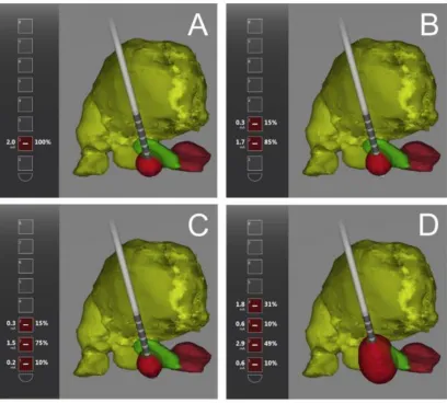
causing facial pulling, limb contraction and contralateral deviation of gaze (Wagle Shukla et al., 2017). Posterior spread of current can stimulate the medial lemniscus and cause paresthesia (tingling, electrical sensation, numbness) and ventral/inferior spread of current can stimulate the SNr and internal capsule fibers, causing mood changes, depression and muscle contractions (Wagle Shukla et al., 2017). As a result, clinical benefit with minimal side effects can only be achieved by steering current away from these structures. Newer systems with multiple independent current sources makes it possible to fractionate current amplitude between two or more active contacts on a lead – a phenomenon known as current steering (Timmermann et al., 2015). DBS devices that allow the fractionation of current using a type of multipolar configuration enables the application of a shaped electrical field (Timmermann et al., 2015). This means that combinations of different percentages allow for differences in electrical field shape (Figure 3; Barbe, Maarouf, Alesch, & Timmermann, 2014). This shaped electrical field can possibly enhance the motor response of patients while minimizing stimulation-related side effects. The Vercise DBS system by Boston Scientific is a current-controlled system that allows for current steering. The Vercise lead consists of eight contact rings, 1.5 mm in length, placed one above the other with 0.5 mm spacing between contacts
overview of present literature investigating the effects of current steering is discussed below.
© Elsevier. Used with permission.
Figure 3: Altered electrical field shape using current steering
Electrode location shown in anatomical relation to the thalamus (yellow), STN (green), and red nucleus (maroon). A: 100% of the current amplitude delivered from contact #2 is a monopolar stimulation creating a spherical electrical field (red). B: Current amplitude fractionation over two contacts shifts current field (red) more dorsally. C: Current amplitude fractionation over the bottom three contacts (10% on contact #1, 75% on contact #2, 15% on contact #3) produces a non-spherical electrical field (red). D: Current amplitude fractionation over four contacts further elongates the electrical field (red) to stimulate more dorsal structures such as the zona incerta.
1.2.5.1 Studies investigating current steering during STN-DBS
devices into the market. Most studies have either focused on the safety and efficacy of the new DBS system or have used computational modeling to predict the volume of tissue activated with current steering, but few have directly tested current steering settings on PD patients undergoing STN-DBS. One of the most cited studies in this area is the VANTAGE study; a multicenter, non-randomized clinical trial evaluating the multiple-source, constant-current Vercise DBS system by Boston Scientific. 40 PD patients who underwent bilateral STN-DBS were assessed 12, 26, and 52 weeks after implantation; the primary endpoint was the mean change in Unified Parkinson’s Disease Rating Scale
(UPDRS) motor scores from baseline to 26 weeks after implantation in the stimulation-on, medication-off state (Timmermann et al., 2015). The treating clinician identified the contact that provided the best clinical effect and in the case of side effects or absence of efficacy, current was fractionalized over the ideal contact and the next best contact (Timmermann et al., 2015). PD patients significantly improved by 62.6% (+/- 19.8) when comparing baseline UPDRS motor scores with six month postoperative scores. At 26 and 52 weeks post implantation, approximately 70% of stimulation programs had current fractionalized over two or more contacts. The remaining programs used a monopolar configuration. This study shows that in the case of suboptimal DBS therapy, the use of current steering across two or more contacts can be used to suppress motor symptoms more effectively than monopolar configurations.
A case study published in 2014 was the first report showing the effects of multiple source current steering in humans. The case focused on a single patient, a 60-year-old male diagnosed with PD for 13 years, who was treated with bilateral STN-DBS with the Vercise DBS system. Before surgery, he had a levodopa response of almost 80% based on UPDRS motor scores, however medications resulted in severe dyskinesia resulting in social life exclusion (Barbe et al., 2014). One week after implantation, the left lead was programmed with a monopolar stimulation setting, whereas the right lead needed more fine tuning with current steering. A standard monopolar review is a post-operative programming strategy that individually tests each stimulation contact on a lead by
four contacts. Contact #2 (from ventral to dorsal) received 50% current stimulation because the monopolar review identified this contact as producing the best therapeutic effect, however further increasing amplitude on contact #2 induced dyskinesia (Barbe et al., 2014). Contact #3 received 10% current stimulation to reshape the field and maintain the clinical effect of contact #2 (Barbe et al., 2014). Contact #4 received 30% current stimulation because the authors assumed further improvement in tremor and dyskinesia was due to the stimulation of the zona incerta (for tremor alleviation) and pallidofugal fiber tracts (for dyskinesia alleviation) located dorsal to the STN (Barbe et al., 2014). Contact #1 received 10% current stimulation because the patient continued to experience some apathy and the authors hypothesized that improvement of apathy with contact #1 stimulation was due to targeting of the limbic STN (Barbe et al., 2014). With this current steering setting, the patient’s UPDRS motor score improved from 45 points before
therapy to 15 points with DBS and their levodopa dose decreased by 70% three months after surgery (Barbe et al., 2014). Over two years after the surgery, the patient was still reporting excellent results including clear speech, good gait, excellent postural reflex, no rest tremor and only tiny action tremor (Barbe et al., 2014). Overall, this case report showed that current steering minimized side effects and led to a good reduction of all PD motor symptoms.
A pilot study using a novel directional DBS device was published in 2016 to evaluate the effects of current steering in horizontal directions. Seven PD patients implanted with the novel directional lead underwent bilateral STN-DBS; the novel lead has four electrode levels with the two middle levels split into three segments spanning approximately 120 degrees (Steigerwald, Müller, Johannes, Matthies, & Volkmann, 2016). Each segment is capable of independent stimulation such that 100% of current amplitude is capable of being delivered from approximately one third of the contact ring. An extended monopolar review during the first postoperative week determined a therapeutic window for 111 directional settings and 24 ring-mode settings across the seven patients. Although there was high variability between leads and directional settings, there was a general trend of an expansion of the therapeutic window with the directional settings (Steigerwald et al., 2016). Overall, this study shows the effects of directional current steering in the
ring-mode stimulation. The benefits of directional stimulation were best appreciated in cases of suboptimal electrode positions resulting in a narrow therapeutic window. Suboptimal lead positioning can occur at any stage during the DBS procedure.
1.3 STN-DBS procedure
The DBS procedure might vary between neurosurgical teams with regards to equipment, however the surgical techniques are similar. The planning of the procedure starts off by using pre-operative MRI scans, which are used to construct the stereotactic target using graphic tools and various atlases that are available on navigation software (Benabid, Chabardes, Mitrofanis, & Pollak, 2009). The planning stage allows surgeons to choose an entry point that will avoid puncturing vessels, including those located at the cortical surface, ventricle, or caudate nucleus. With the patient in a stereotactic head frame, the anterior and posterior commissures are identified; STN coordinates are based on a stereotactic brain atlas at 12 mm lateral, 2 mm posterior and 5 mm caudal to the midcommissural point (Yoon & Munz, 1999). An incision in the scalp is then made according to the desired trajectory of the lead and a burr hole is drilled. The planned track is used for electrophysiological exploration using multiple microelectrodes; participants of the current thesis usually had five microelectrodes initially inserted for exploration. Typical firing patterns obtained from the microelectrode recording (MER) is used for STN localization; asymmetrical spikes at high frequency with bursting patterns are characteristic features of the STN, whereas symmetrical spikes of large amplitude and regular activity are characteristic of the SNr (Benabid et al., 2009). Firing patterns along with patient feedback from stimulation of the microelectrodes (patient is awake with local anesthesia) is used to determine optimal placement of the chronic/permanent DBS lead. The IPG is inserted under general anesthesia into a subcutaneous pouch in the
subclavicular area (Benabid et al., 2009).
1.3.1 Reasons for lead misplacement
performed using T2-weighted MRI images whose quality can be compromised enough to affect visualization of the STN. 7 Tesla (T) MRI, which uses a stronger magnet than the more common 1.5 T or 3 T MRI, offers higher contrast-to-noise T2-weighted images, but its current clinical applicability is limited (Fasano & Lozano, 2015). T2-weighted images in general contain substantial blooming artifacts that cause distortion and prevent the precise localization of the STN (Fasano & Lozano, 2015). Even if pre-operative planning is adequate to continue, complications and minor mishaps during the actual surgical procedure can contribute to lead misplacement. If the frame is misaligned or shifts during surgery, the lead may deviate to an unintended target (Ellis et al., 2008). As discussed above, intraoperative MER is used for verification of lead localization; however, errors due to poor technique or interpretation of MER data can jeopardize accuracy. Brain shifts may also occur at any time in the surgical process, including preoperative imaging, microelectrode recording, lead placement, or when a cerebrospinal fluid leak is detected (Ellis et al., 2008). Additionally, lead deflection is possible due to changes in tissue density, the angle of approach, or collision with the burr hole or the capping device (which fastens the permanent lead into place) (Ellis et al., 2008). Given the numerous reasons for lead misplacement, current steering—to an extent—allows stimulation to be directed toward the target region. As discussed next, the target region for each symptom may differ due to differences in pathology.
1.4 Pathophysiology of bradykinesia
The term bradykinesia covers a range of problems in the control of movement; in all cases, the principal deficit is that movements are slow (Berardelli, 2001). Bradykinesia is often used synonymously with the terms akinesia and hypokinesia. Specifically,
2016). Although secondary factors such as muscle weakness, tremor and rigidity may contribute to bradykinesia, primary bradykinesia is potentially due to slowness in
formulating the instructions to move (i.e. programming) or to slowness in executing these instructions (Berardelli, 2001). Based on studies that reflect motor execution as well as programming, bradykinesia seems to result primarily from the underscaling of movement commands in internally generated movements (i.e. in the absence of external cues); this leads to insufficient recruitment of muscle force during the initiation of movement
(Berardelli, 2001). This has led to the suggestion that bradykinesia is a problem of scaling motor output appropriately to the task, rather than to any intrinsic limitation in motor execution (Berardelli, 2001). Deficits in movement preparation in PD patients have been supported by slower reaction times and slower increase in premovement cortical
excitability, which suggest abnormal retrieval of stored motor commands (Magrinelli et al., 2016).
The pathophysiology of bradykinesia is not completely understood; however, among the cardinal motor symptoms of PD, it fits better with the classical model of basal ganglia function which points at the prevalence of the indirect pathway over the direct one. The details of this model are outlined in section 1.1.1 and visually presented in Figure 1. The prevalence of the indirect pathway in this model is used to explain the pathophysiological hallmark of PD hypokinetic symptoms as resulting from increased neuronal firing in the GPi and SNr, leading to excessive inhibition of thalamocortical and brainstem motor systems and causing interference with the speed of movement onset and execution (Magrinelli et al., 2016). Furthermore, according to this model bradykinesia may result from the failure of basal ganglia output to reinforce cortical mechanisms responsible for the preparation or execution of movement (Magrinelli et al., 2016). The idea that beta synchrony in LFP recordings is implicated in bradykinesia was alluded to in section 1.2.3, which also discussed the finding that DBS was able to suppress the excessive synchronization. To add to this, premovement electroencephalogram (EEG) beta
similarly demonstrated to correlate with improvement in bradykinesia and rigidity, but not tremor (Magrinelli et al., 2016).
1.5 Pathophysiology of rigidity
Rigidity is characterized by increased muscle tone at rest, increased tension during passive movement and increased resistance to stretching (Rodriguez-Oroz et al., 2009). Although both flexor and extensor muscle groups are involved, flexor muscles of the limbs are more affected in the early stages of the disease (Rodriguez-Oroz et al., 2009). Rigidity may be enhanced by voluntary movement of other body parts, and increased resistance is more noticeable when the examined joint is stretched slowly (Magrinelli et al., 2016).
The pathogenesis of PD rigidity has been hypothesized to include changes in the passive mechanical properties of joints, tendons and muscles, the enhancement of stretch-evoked reflexes, and abnormalities in peripheral sensory inputs that can influence the response to muscle stretch (Magrinelli et al., 2016). The way these changes are associated with dopamine deficiency, or basal ganglia output as depicted by the classical model, remains unclear (Magrinelli et al., 2016). The classical model predicts that increased neuronal activity in the GPi/STN and the resulting inhibition of thalamocortical projections should result in decreased muscle activation and reduced response to stretching; however, the opposite is observed with rigidity (Baradaran et al., 2013). Despite the ambiguity, surgical interventions focusing on the basal ganglia and motor thalamus has a proven anti-rigidity effect, indicating a role of the motor circuit in the pathogenesis of rigidity (Rodriguez-Oroz et al., 2009).
Although the pathogenesis of rigidity remains more elusive than other PD cardinal symptoms, evidence points to a stronger link to bradykinesia than to hyperkinetic
symptoms. As discussed above, excessive beta synchronization in LFP recordings relates only to the bradykinetic-rigid state that is reversed by dopaminergic therapy (Eusebio & Brown, 2009). In addition, a longitudinal study looking at the progression of
Suppression of bradykinesia and rigidity also requires lower dosages of levodopa than tremor (Nonnekes, Timmer, Vries, & Rascol, 2016). There is also evidence to show that when stimulating the STN during DBS, dorsal/superior spread of current reaching the internal capsule, thalamus and zona incerta causes improvement in hyperkinetic symptoms including tremor and dyskinesia, but not hypokinetic symptoms (Wagle Shukla et al., 2017). Taken together, these conclusions point toward a relationship between rigidity and bradykinesia management that is separate from tremor.
1.6 Pathophysiology of PD tremor
Tremor, one of the cardinal motor symptoms of PD, is defined as a rhythmic, involuntary, oscillating movement of one or more body parts (Helmich & Dirkx, 2017). Unlike other motor symptoms, tremor severity does not correlate with the degree of striatal dopamine depletion and therefore, tremor response to dopaminergic medication is subpar when compared to bradykinesia and rigidity (Helmich & Dirkx, 2017). Tremor also has many types – the classical PD tremor occurs at rest with a frequency of 4 to 6 Hz (Helmich, Toni, Deuschl, & Bloem, 2013). Many PD patients also have action tremor produced by voluntary contraction of muscle, and includes postural, isometric, and kinetic tremor (Helmich et al., 2013). In 34-60% of PD patients, action tremor can be classified as reemergent resting tremor (Helmich et al., 2013). Reemergent tremor occurs after a delay of two or more seconds after the limb affected by resting tremor assumes a new posture; it occurs at the same frequency as resting tremor and it responds to levodopa (Helmich et al., 2013). Action tremor that is not reemergent tremor occurs at a higher frequency, between 6 and 15 Hz, and it does not respond to levodopa (Helmich et al., 2013). It is possible that reemergent tremor and resting tremor in PD are caused by the same
mechanisms, although this finding has not been previously tested (Helmich et al., 2013). One finding supporting this view is that in many PD patients, voluntary actions suppress resting tremor, but does not completely interrupt it (Helmich et al., 2013).
There is a consensus towards central, rather than peripheral, mechanisms being
the basal ganglia and the ventral intermediate nucleus of the thalamus (Vim) with the same frequency as tremor (Helmich & Dirkx, 2017). An important finding is that pallidal neurons are only transiently and inconsistently coherent with tremor, whereas neurons of the Vim are highly synchronous; this suggests that the thalamus contributes more to the driving force behind tremor (Helmich & Dirkx, 2017). One of the first hypotheses
regarding the pathophysiology of tremor was the thalamic pacemaker theory, which states that hyperpolarized cells in the thalamus act as the tremor pacemaker (Helmich & Dirkx, 2017). The basis for this hypothesis lies in in vitro studies showing that slightly
depolarized thalamic cells oscillate at 10 Hz, whereas hyperpolarized cells oscillate at 6 Hz. These two frequencies coincide with the frequency of physiological tremor and PD tremor, respectively (Helmich, Hallett, Deuschl, Toni, & Bloem, 2012). In the animal model, the 6 Hz oscillatory mode is associated with low threshold calcium spikes, which often follow membrane hyperpolarization. However, this pattern was not observed in the thalamus of tremor-dominant PD patients (Helmich et al., 2012). Other theories argue that the tremor pacemaker resides within the basal ganglia, but the theories remain incomplete due to strong clinical evidence showing the efficacy of Vim-DBS in treating tremor. More recent studies have been used to construct a model that integrates the role of both the basal ganglia and the cerebellothalamic circuits in tremor. The dimmer-switch model of parkinsonian resting tremor introduces the idea of dopaminergic cell death in the retrorubral field, located dorsally and caudally to the SNc.
Although loss of neurons in the SNc has become the pathological hallmark of PD, tremor-dominant patients have milder degeneration of the SNc and instead, more
the cerebellothalamocortical circuit in the generation and maintenance of resting tremor. Rick Helmich and colleagues used concurrent electromyography (EMG) and functional magnetic resonance imaging (fMRI) to show that the basal ganglia operates analogous to a light switch that ‘turns on’ tremor, and the cerebellothalamocortical circuit operates
analogous to a light dimmer that modulates tremor amplitude (Helmich et al., 2012).
© Oxford University Press. Used with permission.
Figure 4: Dimmer-switch model of PD resting tremor
Dopaminergic cell death in the retrorubral area in tremor-dominant PD causes dopamine depletion in the pallidum (in red). This leads to a pathological signal that triggers the cerebellothalamocortical circuit (in blue) through the primary motor cortex. Therefore, the striato-pallidal circuit causes the onset of tremor (analogous to a light switch) while the cerebellothalamocortical circuit produces the tremor and controls its amplitude (analogous to a light dimmer). VLp: ventral posterolateral nucleus of the thalamus.
1.7 Rationale and hypothesis
patient due to differences in disease phenotype or anatomical variations of the target. Current steering is a potential solution to address these issues by steering current to the optimal region in cases of suboptimal lead position, or steering current away from stimulating non-motor areas of the target or neighboring tissue which can cause adverse side effects. Technological advancements have made it possible to create non-spherical electrical field shapes by fractionating current over two or more active contacts. Different electrical field shapes can stimulate desired structures to different degrees of symptom alleviation. Therefore, an optimal electrical field shape would localize current to the desired structure and avoid unintended stimulation of neighboring anatomical structures for optimal symptom improvement. Thus, it was hypothesized that the way the electrical field is shaped affects a patient’s upper limb symptom alleviation.
The goal of the current thesis was to explore the effectiveness of current steering as it relates to appendicular motor symptoms of the upper limbs. These appendicular symptoms include rest tremor, postural tremor, bradykinesia and rigidity. This study tested 16 different current fractionation settings; four of these settings solely employ monopolar stimulation whereas the remaining 12 employ current steering either unilaterally or bilaterally. As touched upon earlier, the current field created by DBS systems that allow for current steering is not limited to the relatively spherical electrical field created by monopolar stimulation. Current steering can be achieved on a horizontal plane—with directional lead technology—and a vertical plane. Directional leads contain contacts that are split into three segments such that fractionation of current can be achieved in horizontal directions. The DBS system used in this study solely explored current steering in the vertical plane, as demonstrated by Figure 3.
1.7.1 Summary of objectives
Given the variations in lead position, symptom phenotype, and anatomical factors across patients, the benefits of current steering and/or monopolar stimulation will differ among patients. For this reason, the first objective tests the effectiveness of current steering settings in comparison to the monopolar settings for optimal symptom alleviation. The first objective is as follows:
1) Determine the optimal current fractionation setting and amplitude for each patient’s upper limb symptom alleviation
The second objective tests if there is a difference in target between the optimal alleviation of hyperkinetic symptoms and hypokinetic symptoms in the same patient. As discussed, the classical model of basal ganglia function (Figure 1) and the prevalence of the indirect pathway over the direct one is the pathophysiological hallmark of PD hypokinetic
management of tremor could possibly involve stimulation of a different region. This means that hyperkinetic symptoms of a limb will be optimally alleviated by settings that differ from those that optimally alleviate hypokinetic symptoms. The second objective is:
2) Compare optimal alleviation between hyperkinetic symptoms, rest and postural tremor, and hypokinetic symptoms, rigidity and bradykinesia, in the same limb
Chapter 2
2
Methods
This section outlines the methods used for the current study. Participants underwent bilateral implantation in the STN of a constant-current DBS system capable of current steering. The current steering investigation lasted approximately four weeks for each patient in which a set of clinical tasks was performed after each setting change. Study assessment tools included the UPDRS-III examination as well as motion capture technology that was used to quantify bradykinesia, postural tremor, rest tremor, and rigidity of the upper limbs.
2.1 Study participants
Seven PD patients who underwent bilateral STN-DBS were included in this study analysis; Table 1 outlines the participant demographics. This study was approved by the Human Research Ethics Board at Western University (REB #108453). The following lists the inclusion criteria for candidates of the study: (1) idiopathic PD with a 30%
improvement in symptom response to levodopa treatment, assessed by the UPDRS, (2) II or IV Hoehn-Yahr stage, (3) disabling motor fluctuations with off periods and dyskinesia during on phases, (4) assessed for eligibility for the DBS procedure, (5) able to give informed consent, (6) able to visit the clinic for assessment, (7) no dementia or
psychiatric abnormalities on neuropsychological testing. The following lists the exclusion criteria for candidates: (1) previous brain surgery or cardiac pacemaker, (2) moderately severe parkinsonism in the context of unstable pharmacological treatment, (3) dementia as assessed by the Diagnostic and Statistical Manual of Mental Disorders (DSM) V criteria, (4) severe psychiatric symptoms such as hallucinations and depression, (5) bad general health, (6) lack of compliance at follow-up visits. All patients in this study had implantation of the constant-current, multiple-source Vercise DBS System by Boston Scientific; however, the type of lead implanted (non-directional vs. directional) differed among patients. Note that although four out of the seven study subjects had a directional lead implanted, current steering was only investigated in the vertical plane for all
Table 1: Participant pool demographics
Participant ID
Age (yrs) Sex PD Duration (yrs) BSC 01 BSC 02 BSC 03 55 52 69 M M M 8 12 14 BSC 05 BSC 06 BSC 07 BSC 08 Mean (SD) 63 57 75 61 61.71(±8.10) F F F F - 17 12 10 14 12.43(±2.94) SD: standard deviation of the mean
2.2 Assessment tools
To quantify motor symptoms, a standardized clinical scale and a wearable motion capture system was used. The UPDRS is the most commonly used scale to follow the course of PD; part III of this scale is a whole-body motor evaluation that assesses the severity of certain tasks on a scale of zero to four, zero being normal and four being the most severe (see Appendix 3). Most literature on the clinical effects of PD use the motor UPDRS score to quantify symptoms. The problem with this clinical rating scale is that it is subjective to the rater’s discretion. Although the examining neurologist or researcher undergoes the same training to administer the UPDRS, the interpretation of the severity of certain motor symptoms can vary from person to person. In addition to the UPDRS motor score, the current thesis used objective kinematic measures to track and quantify body movements similar to motion capture technology used in the entertainment industry.
2.2.1 Motion capture system
(IMU) sensors that are located all over the body and provide information about body segments. Since the current project was only looking at upper limb movements, the wearable motion capture system in this study consisted of IMU sensors placed along the arm (according to Figure 5; Delrobaei, Tran, Gilmore, McIsaac, & Jog, 2016). The sensors include 3D accelerometers, 3D gyroscopes and 3D magnetometers within each unit. The relative position and orientation between adjacent sensors enable a fusion software to identify joint angles. The first study subject (BSC 01) started off using IMU sensors from the animation company Synertial Ltd. but switched to sensors from the company Xsens due to better magnetic field detection; the rest of the participants had all their study visits completed with the Xsens sensors. Data acquisition was performed at 60 Hz sampling rate using Xsens MVN 2018 software. For more details regarding the IMU hardware and fusion software, please refer to the study by Delrobaei and his colleagues in 2016 which used a similar procedure to assess PD bradykinesia using wearable
technology (Delrobaei et al., 2016).
© Elsevier. Used with permission.
Figure 5: Position of IMU sensors on the upper limbs
Four sensors are placed on each arm, along the hand, forearm, upper arm, and shoulder, while patients engage in the clinical tasks.
2.3 Clinical tasks and study timeline
seconds. The task was performed individually for each arm and repeated for a total of two trials per arm. Kinematic data was collected using the motion capture system and clinical scale data was collected using item 3.6 (pronation-supination movements of hands) of the UPDRS-III examination. This task was validated against the respective UPDRS item using an IMU-based motion capture system in a study by Delrobaei and colleagues (Delrobaei et al., 2016). To evaluate upper limb rest and postural tremor, all participants were asked to perform and repeat the following tasks for a total of two trials:
1) Rest tremor: while sitting, participants rested both of their forearms on the arms of a chair with their wrists hanging off the edge for at least 20 seconds.
2) Postural tremor: while sitting, participants fully extended their arms forward with hands pronated at shoulder height level for at least 20 seconds.
Kinematic data was collected using the motion capture system and clinical scale data was collected using item 3.17 (rest tremor amplitude) and item 3.15 (postural tremor of the hands) of the UPDRS-III examination. The two tasks were validated against the respective UDPRS-III items using an IMU-based motion capture system in a second study by Delrobaei and colleagues (Delrobaei et al., 2018). Rigidity of the upper limbs was only evaluated using item 3.3 (rigidity) of the UPDRS-III examination.
Figure 6: Study timeline
As outlined on the timeline in Figure 6, study participants were first assessed within one week prior to their DBS surgery to determine their response to levodopa medication. Patients arrived at this visit off any form of levodopa medication for 12+ hours;
kinematic and UPDRS-III data were collected in the medication-off state according to the clinical tasks mentioned above. Patients were then instructed to take 135% of their usual levodopa dose and wait approximately 45 minutes for maximal effect of the medication; kinematic and UPDRS-III data were collected in the medication-on state. At least four weeks after their DBS surgery, device turn-on occurs. During this visit, a standard monopolar review of the bottom (ventral) four contacts on the right and left leads was performed by stimulating each contact individually and increasing current amplitude in increments of 0.5 mA. An efficacy threshold (minimum amplitude at which improvement in symptoms occur) and adverse effect threshold (amplitude at which the patient begins to experience side effects) were used to determine a therapeutic window of current for each contact. The best contact is one with both a large therapeutic window, and one that requires the least amount of current to produce symptom benefit. The best and next best contact was determined for each patient for current fractionation to occur. Most patients went home from their device turn-on visit on a monopolar stimulation at a minimal level of current (~0.5 mA), with the best contact that was identified on each side of the brain. All patients were programmed with a frequency of 130 Hz for the entire duration of the study and all patients were programmed with a pulse width of 60 µs, except BSC 01 who was programmed with 90 µs. The choice for stimulation frequency and pulse width as 130 Hz and 60 µs was based on majority of literature showing these values to be clinically effective.
settings were randomized across patients such that each patient did not receive the same order of settings within the week. The same set of 16 settings was repeated in the same order for each patient in the following weeks at increasing amplitudes. During the first of the four weeks, the amplitude was set at 20% of the patient’s therapeutic window (TW) according to the following equation:
𝑊𝑒𝑒𝑘 #1 𝐴𝑚𝑝𝑙𝑖𝑡𝑢𝑑𝑒 = 𝐿𝑜𝑤𝑒𝑟 𝑙𝑖𝑚𝑖𝑡 𝑜𝑓 𝑇𝑊 + (0.20 𝑥 𝑇𝑊) (1)
The same method was used to calculate the amplitude for week #2, week #3, and week #4 at 40%, 60%, and 80% of each patient’s therapeutic window, respectively. Note that for BSC 08 only, the amplitude was set at 60% of the therapeutic window at week #4 instead of week #3, and 80% of the therapeutic window at week #3 instead of week #4. However, for simplification, ‘Week 3’ indicated on Tables 6-13 signifies a testing amplitude that
was 60% of the therapeutic window for all patients, and likewise ‘Week 4’ signifies a testing amplitude that was 80% of the therapeutic window for all patients. The following settings were not tested at the respective week’s amplitude for the mentioned participants:
setting 13 at week 4 amplitude for BSC 03, setting 13 at week 3 and 4 amplitude for BSC 07. The reason for not testing was due to unmanageable dyskinesia that caused
discomfort to both participants and interfered with testing equipment.
Patients arrived each day off any levodopa medication for 12+ hours. After each current steering setting was programmed, a 25-minute wait period was given to allow for the stimulation to take effect. Kinematic and UPDRS-III data was collected after each setting change while the patient performed the clinical tasks mentioned above. At the end of each day following the four setting changes, the patient went home with a baseline setting. During the first week of the current steering investigation, patients went home with a baseline setting that fractionated current equally between the best and next best contact (50%-50% split) on the left and right leads, at a minimal amplitude of current. At the end of the week, patients went home with a setting from the 16 tested settings that provided the greatest clinical benefit according to a total-body UPDRS-III score, at the week’s testing amplitude; this became the new baseline setting with which the patients
by going home on the setting and corresponding amplitude that was optimal across all weeks, again according to a total-body UPDRS-III score (Table 5).
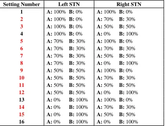
Table 2: Current fractionation settings
STN: subthalamic nucleus; A and B represent the best two contacts at the left and right STN; setting numbers in red indicate settings where current steering occurs either unilaterally or bilaterally; the remaining four settings employ bilateral monopolar stimulation.
2.3.1 Feature extraction
Joint angles were obtained from the four IMUs placed along the wrist, elbow, and shoulder of each arm (Figure 5). For bradykinesia assessment, the following features were extracted from each joint angle to analyze upper limb motion: standard deviation of the signal (STD), angular velocity (Vel), and variability in terms of time (Time_Var) and amplitude (Amp_Var). Joint angle signals were extracted and analyzed for three arm joints to examine wrist rotation relative to the elbow, elbow rotation relative to the shoulder, and shoulder rotation relative to the fixed back reference. For more information regarding the feature extraction process, please refer to section 2.3 of the study published by Delrobaei and his team (Delrobaei et al., 2016). An improvement in bradykinesia would show increases in STD and Vel, and decreases in Time_Var and Amp_Var. From
Setting Number Left STN Right STN
1 A: 100% B: 0% A: 100% B: 0%
2 A: 100% B: 0% A: 70% B: 30%
3 A: 100% B: 0% A: 50% B: 50% 4 A: 100% B: 0% A: 0% B: 100%
5 A: 70% B: 30% A: 100% B: 0%
6 A: 70% B: 30% A: 70% B: 30%
7 A: 70% B: 30% A: 50% B: 50%
8 A: 70% B: 30% A: 0% B: 100%
9 A: 50% B: 50% A: 100% B: 0%
10 A: 50% B: 50% A: 70% B: 30%
11 A: 50% B: 50% A: 50% B: 50%
12 A: 50% B: 50% A: 0% B: 100% 13 A: 0% B: 100% A: 100% B: 0%
14 A: 0% B: 100% A: 70% B: 30%
this, the bradykinesia index (BKI) calculation can be derived to quantify bradykinesia for the repetitive pronation-supination task:
(1)
The BKI can be calculated individually at each joint involved in generating the arm rotation such that a BKI for the wrist (BKIWrist), elbow (BKIElbow), and shoulder
(BKIShoulder), is computed. In the referenced study (Delrobaei et al., 2016), a total arm
BKI was calculated according to equation (2) below. However, for the current thesis BKIShoulder was omitted because shoulder rotation was much slower in the participants
relative to wrist and elbow rotation and thus total arm BKI was not an accurate reflection of their bradykinetic state. In addition, joint angle signals for the wrist and elbow are combined; the reason for the combined signal is because the relative position of the forearm sensor to the hand and upper arm sensors affects the individual joint angle signals from the wrist and elbow. Therefore, instead of using BKIWrist and BKIElbow that
are calculated using joint angles from the wrist and elbow, respectively, the combined signal was used to calculate a total forearm BKI (BKIForearm) that better reflects the
patient’s upper limb bradykinetic state (equation (3)).
(2)
(3)
as the TSS for that joint. The RMS of all joints associated with each limb’s TSS was calculated as the TSS for that limb. Therefore, the TSS for each arm is calculated according to equation (4).
Table 3: List of joint angles for tremor assessment
Body part Segment Motion
Right arm Right wrist Flexion/extension
Ulnar/radial
Pronation/supination
Right elbow Flexion/extension
Pronation/supination
Right shoulder Flexion/extension
Abduction/adduction Rotation
Left arm Left wrist Flexion/extension
Ulnar/radial
Pronation/supination
Left elbow Flexion/extension
Pronation/supination
Left shoulder Flexion/extension
Abduction/adduction Rotation
𝑇𝑆𝑆 = 𝑅𝑀𝑆 [𝐹4−20𝐻𝑧(𝐽𝑖)] (4)
Ji is the ith joint movement; the maximum number of joint movements involved in the
calculation for each arm is eight (see Table 3). F4-20Hz represents signals filtered from 4
Hz to 20 Hz, and RMS represents the root-mean-square of all joints forming the signal. For more information regarding the TSS calculation, refer to section 2.4 in the study published by Delrobaei and his colleagues who used the same procedure for monitoring whole-body tremor using wearable technology (Delrobaei et al., 2018).
2.4 Data analysis
To determine each patient’s weekly optimal setting from kinematic data, raw BKI and