A Novel Six-Band Polarization-Insensitive Metamaterial Absorber
with Four Multiple-Mode Resonators
Guo-Qing Xu1, Zong-De Ju1, Zhi-Hua Wei1, Jing Li1, Qian Zhao2, and Jie Huang1, *
Abstract—A novel six-band metamaterial absorber based on four multiple-mode Ω-shaped resonators (MMORs) is presented, analyzed and measured in this paper. The discrete absorption responses, determined by horizontal-oriented and vertical-oriented MMORs, can be combined to add the total number of absorption peaks. Among the six absorption peaks, four absorption peaks are excited by horizontal-oriented MMOR, and the other two are excited by vertical-oriented MMOR. The absorber, composed of a simple resonators-dielectric-sheet sandwich structure, has six distinct near-perfect absorption peaks with the polarization-insensitive characteristic in the frequency range from 2 to 17 GHz. To reveal the physical mechanism of the absorber, the distributions of the surface current and power loss density, and the equivalent circuit model are also investigated at the six absorption peaks. Moreover, the measured results are in good agreement with the simulated ones and show that the average absorption rate of the proposed absorber is over 97.21%.
1. INTRODUCTION
Metamaterials have been greatly developed since the first one was confirmed by Smith et al. in 2000 [1]. Due to the exotic electromagnetic characteristics, the metamaterials have been widely applied in filters [2], antennas [3], polarization converters [4], absorbers [5], etc. Compared with classical absorbers, the absorbers based on metamaterials have the advantages of light weight, small size and nearly perfect absorption [5]. However, in the early stage, most of the metamaterial absorbers (MMAs) are single-band [6, 7] or polarization-sensitive [8, 9]. To achieve different features, such as multiband and polarization-insensitive [10–18], many efforts are put to develop the MMAs, and a variety of design methods have been reported in the past few years. For a multi-band absorber, the reported design methods can be mainly classified into three types. The first one is to integrate multiple different resonators into a single cell. The second one is to stack multiple layers with different resonators in vertical direction. The third one is to excite multiple resonance modes with only single resonator in the unit cell. Compared with the first two types of methods above, the last one has the characteristics of ultra-thin thickness and small size. However, it will get into the trouble that the structure of the resonator becomes more and more complicated as absorption band increases [19–21]. Moreover, these methods are only suitable for designing dual-band, triple-band and quad-band absorbers. So, an effective design method is still absent for designing super multi-band (≥ 5) MMAs which possess the characteristics of polarization-insensitive and nearly prefect absorption. A concept, attempting to construct the super multi-band absorber, is still interesting. The concept proposed here originates from a phenomenon observed by Wang et al. [22], i.e., different absorption peaks can appear when the resonator is polarized under 0◦ and 90◦ polarization angles. Thus, by placing two same resonators in the vertical and horizontal directions, integrating absorption performances of 0◦polarization angle with that
Received 2 June 2017, Accepted 21 August 2017, Scheduled 28 August 2017
* Corresponding author: Jie Huang (jiehuang@swu.edu.cn).
1 College of Engineering and Technology, Southwest University, Chongqing 400715, China. 2 College of Physical Science and
of 90◦ polarization angle may be achieved. To further achieve the property of insensitive polarization, it is better to utilize a symmetric structure. Finally, the absorber with four same resonators is proposed. In this paper, we design a novel six-band MMA by utilizing the new design strategy mentioned above. The absorber proposed here is composed of a continuous metallic sheet, a dielectric substrate and an array of four multiple-mode Ω-shaped resonators (two horizontal-oriented resonators and two vertical-oriented resonators). Among the six resonance modes, four modes are excited by horizontal-oriented resonators, and the other two are excited by vertical-horizontal-oriented resonators. Multiple simulations and experiments demonstrate that the MMA has the characteristics of polarization-insensitivity and nearly prefect absorption. Therefore, the MMA proposed here can be applied in massive related areas, such as thermal detectors, imaging and stealth technology.
2. STRUCTURE AND DESIGN
The unit cell of the proposed MMA is composed of four MMORs and a metallic ground sheet separated by a dielectric substrate, as depicted in Fig. 1. The MMOR consists of a split ring and two arms. To realize the electromagnetic responses of horizontal and vertical polarizations simultaneously, the four MMORs (orderly named R1, R2, R3 and R4) are placed along the horizontal and vertical orientations of the unit cell. The dielectric substrate is FR-4 with a 1.2 mm thickness (h) and relative refractive index of n = 2.074 +i0.026. The MMORs and metallic ground sheet are designed by using copper with a conductivity of σ = 5.8×10⁷S/m, and the thickness t is 0.035 mm. The optimized dimension parameters are as follows (unit in mm): P = 20, L = 18, W1 = 1, W2 = 2.65, W3 = 1.25, L1 = 4.75, L2 = 3.925,g= 0.5 and s= 0.5.
(a) (b) (c)
Figure 1. Schematic of proposed structure, (a) the MMOR, (b) front view of unit cell, (c) cross section of unit cell.
The numerical result of the proposed MMA is simulated by the finite element method (FEM). The unit cell boundary conditions are set in the x and y directions. A normal incident plane wave, propagating along the z direction, is used as the excitation source with the electric field polarized along the y direction (TE polarization). The absorption rate can be calculated by the expression [5]: A(ω) = 1−R(ω)−T(ω), in whichR(ω) equals the square of the reflection coefficientS11(ω), andT(ω)
equals the square of the transmission coefficient S21(ω). The transmission coefficient is approximately
3. SIMULATION RESULT AND DISCUSSION 3.1. Numerical Analysis on Absorption Performances
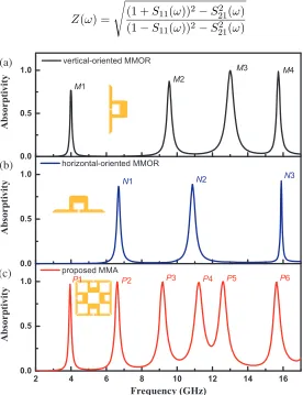
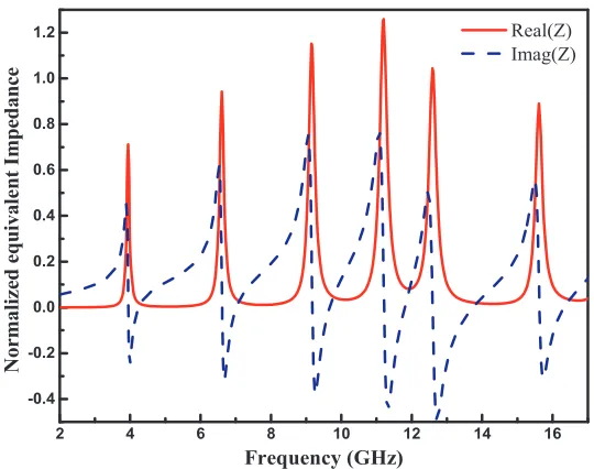
The absorption spectrum of single vertical-oriented MMOR under normal incidence and 0◦ polarization angle is presented in Fig. 2(a), where the MMOR shows four obvious absorption peaks at 3.98 GHz (M1), 9.55 GHz (M2), 13.01 GHz (M3) and 15.73 GHz (M4). When the MMOR is rotated to the horizontal direction, the MMOR correspondingly presents three absorption peaks at 6.68 GHz (N1), 10.86 GHz (N2) and 15.90 GHz (N3), as shown in Fig. 2(b). Then a four-fold symmetrical structure, composed of two horizontal-oriented MMORs and two vertical-oriented MMORs, is proposed to form a polarization-insensitive absorber, and the absorption spectrum is also shown in Fig. 2(c). The absorption spectrum contains six obvious absorption peaks at 3.95 GHz, 6.61 GHz, 9.17 GHz, 11.22 GHz, 12.59 GHz, and 15.63 GHz, and the corresponding absorption rates are 97.04%, 99.57%, 99.54%, 98.95%, 99.94%, and 99.49%, respectively. The six absorption peaks are orderly named mode P1, P2,P3, P4, P5 and P6. It can be found that the absorption response of the proposed MMA is determined by the combination of the absorption responses of the horizontal-oriented and vertical-oriented MMORs. Especially, the absorption peak at 15.73 GHz (M4) excited by the vertical-oriented MMOR and the absorption peak at 15.90 GHz (N3) by the horizontal-oriented MMOR are very close to each other, and then the two peaks merge into one peak at 15.63 GHz (P6). As presented in Fig. 3, the proposed MMA shows six absorption peaks in the normalized impedance spectrum, and these frequencies are consistent with the absorption frequencies of modes P1 ∼P6. The normalized impedance can be calculated by following formula [23].
Z(ω) =
(1 +S11(ω))2−S212 (ω)
(1−S11(ω))2−S212 (ω)
0.0 0.5 1.0 0.0 0.5 1.0
2 4 6 8 10 12 14 16
0.0 0.5 1.0 (c) (b) M4 M3 M2 A b sorptivi ty vertical-oriented MMOR M1 (a) N3 N2 N1 Ab so rp ti vity horizontal-oriented MMOR P6 P5 P4 P3 P2 P1 A b sor p ti vity Frequency (GHz) proposed MMA
2 4 6 8 10 12 14 16 -0.4
-0.2 0.0 0.2 0.4 0.6 0.8 1.0 1.2
Norma
li
zed e
qui
val
en
t
Im
ped
ance
Frequency (GHz)
Real(Z) Imag(Z)
Figure 3. The normalized equivalent impedance of the proposed MMA.
(a) (b) (c) (d) (e) (f)
(g) (h) (i) (j) (k) (l)
mode P1 mode P2 mode P3 mode P4 mode P5 mode P6
Figure 4. The surface current distributions of (a)–(f) top and (g)–(l) bottom layers at (a) and (g) modeP1, (b) and (h) mode P2, (c) and (i) mode P3, (d) and (j) mode P4, (e) and (k) modeP5, and (f) and (l) modeP6, respectively.
Moreover, the normalized impedance of the MMA is close to that of free space at the six absorption peaks, resulting in perfect impedance matching.
contrary, the surface currents at modes P2 and P4 mainly appear at the vertical-oriented MMORs (R1 and R3), which suggests that the two strong absorption peaks originate from the response of the MMOR under 90◦ polarization angle. These results are consistent with those in Fig. 2, which validates that the absorption response of the proposed MMA is determined by the combination of the absorption responses of the horizontal-oriented and vertical-oriented MMORs.
To better understand the absorption mechanism, the power loss density distributions in the interface between the top metal and the medium and the vertical (a-a) or horizontal (b-b) cutting plane at six absorption peaks are analyzed and shown in Figs. 5(a)–(f), respectively. The power loss density mainly occurs in the edge and gap of the MMOR. The maximum power loss takes place in the interface, and then the absorbed power is totally dissipated in the substrate. It should be noted that the power losses at modes P1, P3, P5 and P6 are concentrated in the horizontal oriented MMORs. And the power losses at modes P2 and P4 are concentrated in the vertical oriented MMORs. This characteristic of power loss density is consistent with the absorption performances determined by the combination of the horizontal and vertical MMORs.
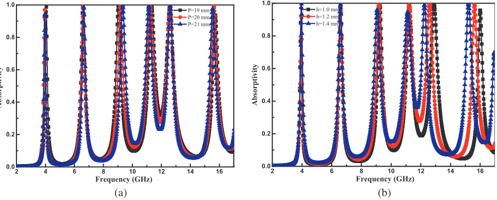
Furthermore, the sensibility of the proposed MMA is investigated by tuning several main dimension parameters. The absorption spectrum for variation of the period P is illustrated in Fig. 6(a). When period P increases from 19 to 21 mm, the frequencies of modes P1, P3, P4 and P6 have a blueshift, while the absorption frequencies of modes P2 and P5 keep nearly unchanged. Thus, the absorption frequencies can be optionally modulated by changing periodP. For thicknessh of the dielectric layer, as shown in Fig. 6(b), when h varies from 1.0 to 1.4 mm, the absorption strengths of all the modes go beyond 95%, indicating that the absorber can maintain high performance in practical fabrication even if there is a thickness deviation in the dielectric layer.
(a) mode P1 (b) mode P2 (c) mode P3 (d) mode P4 (e) mode P5 (f) mode P6
a-a' b-b' a-a' b-b' a-a' a-a'
a
a' b b' b b'
a
a'
a
a' a
a'
Figure 5. The power loss density distributions of the proposed MMA at different absorption frequencies.
2 4 6 8 10 12 14 16
0.0 0.2 0.4 0.6 0.8 1.0
Absorptivit
y
Frequency (GHz)
P=19 mm P=20 mm P=21 mm
2 4 6 8 10 12 14 16
0.0 0.2 0.4 0.6 0.8 1.0
A
b
sorptivit
y
Frequency (GHz)
h=1.0 mm h=1.2 mm h=1.4 mm
(a) (b)
Figure 7(a) depicts the simulated absorption spectrum under different polarization angles for the case of normal incidence. As observed, when the polarization angle changes from 0◦ to 90◦, the absorption performance of the proposed MMA keeps almost unchanged. It suggests that the proposed MMA has the characteristics of polarization-insensitive absorption and can be used to the applications which are independent of polarization. Figs. 7(b) and (c) illustrate the simulated absorption spectrum of the proposed MMA for different oblique incident angles (θ, defined as the angle between the wave vector and z axis) for TE and TM polarization waves, respectively. For the case of TE polarization, the resonance frequencies of modes P1, P2, P3 and P4 are nearly unchanged as θ increases, and the absorption rates remain above 80%. When θ increases to 30◦, the resonance frequency of mode P5 has a blueshift, and an additional absorption peak appears between the 11.22 GHz (P4) and 12.59 GHz (P5). Especially, with the increase of θ, the absorption rate of mode P6 gradually decreases because the magnetic field decreases and cannot effectively excite resonance absorption under the large incident angle and TE polarization [25]. For the case of TM polarization, the resonance frequencies of modesP1, P2, andP3 keep nearly unchanged asθ increases, and their absorption rates are more than 90%. The resonance frequencies of modesP4 and P5 have a redshift. In particular, whenθ increases to 45◦, the absorption peak of modeP6 changes from 15.58 GHz to 13.57 GHz, and an additional peak is generated at 16.2 GHz with an absorption rate of 63%.
(a) (b) (c)
TE TM
Figure 7. Simulated absorption spectrum of the MMA for (a) different polarization angles, and different incident angles under (b) TE and (c) TM polarizations, respectively.
3.2. Equivalent Circuit Model
To further understand the resonance mechanism of the proposed MMA, the equivalent circuit model has been investigated. Due to the similarity between the circulating current loop excited by magnetic field in the absorber and the one excited by a source in the parallel LC resonant circuit, the multi-band absorber can be considered as a cascaded parallel LC resonant circuit [26, 27]. Each absorption frequency is determined by its corresponding parallel LC resonant circuit, as shown in Fig. 8. The input admittance Y of each parallel LC resonant circuit can be calculated by Eq. (1), where R, L, and C represent the effective resistance, effective inductance and effective capacitance, respectively. In order to achieve perfect absorption at each absorption frequency, the input impedance Z (Z = 1/Y) of each parallel LC resonant circuit should match the wave impedance of the incident electromagnetic wave (Z = 377 Ω). Ignoring the small loss of metal (R≈0), the resonance frequency (absorption frequency) of the corresponding LC circuit can be simplified as Eq. (2) according to the circuit resonance conditions.
Y = 1
R+jωL +jωC (1)
f0 =
1
2π√LC (2)
Figure 8. The equivalent circuit model for each absorption frequency.
absorption frequency. The inductanceLcan be approximated by the formula: L=μ∗h∗l/w [28, 29]. μ is the permeability of the dielectric, andlandware the length and width of the metal which the surface current flows through. OnceL,Y andf0are fixed, then parametersRandCcan be extracted by Eq. (1)
and (2). An equivalent circuit model of each LC resonant circuit is built in Advanced Design System (ADS) and shown in Fig. 8. The parameters of lumped elements at six different absorption frequencies are determined as L1 = 317.22 pH, C1 = 5.12 pF, L2 = 147.44 pH, C2 = 3.93 pF, L3 = 122.96 pH,
C3= 2.45 pF,L4= 86.63 pH, C4 = 2.32 pF,L5 = 78.31 pH,C5= 2.04 pF,L6 = 61.48 pH,C6 = 1.69 pF.
The resistance R in the equivalent circuit model, related with the losses of absorber, can be used to tune the absorption rate and bandwidth.
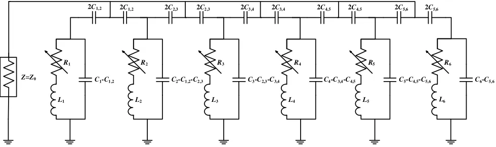
The coupling equivalent circuit model, as shown in Fig. 9, is employed to consider the coupling effect between two adjacent LC resonant circuits, and a coupling capacitance Ci,i+1 between the (i)-th and
(i+1)-th LC resonant circuits is inserted. The coupling capacitance needs to be bisected equally in series, and the excitation port is loaded at AA’ for the analysis in ADS. The initial value of coupling capacitance Ci,i+1 can be calculated by Eq. (3) for the asynchronously-tuned coupled resonators [30]. In ADS, the
optimized coupling capacitances are as follows: C1,2 = 0.062 pF, C2,3 = 0.056 pF, C3,4 = 0.059 pF,
C4,5= 0.059 pF,C5,6 = 0.061 pF.
Ci,i+1=
CiCi+1−
1 ω2
iω2i+1LiLi+1
(3)
Figure 9. The coupling equivalent circuit model of two adjacent circuits.
R5
L5
C5-C4,5-C5,6
R4
L4
C4-C3,4-C4,5
R3
L3
C3-C2,3-C3,4
R2
L2
C2-C1 ,2-C2 ,3
R1
L1
C1-C1 ,2
R6
L6
C6-C5,6 2C1,2 2C1,2 2C2,3 2C2 ,3 2C3 ,4 2C3,4 2C4,5 2C4,5 2C5,6 2C5,6
Z=Z0
Figure 10. The complete equivalent circuit model.
2 4 6 8 10 12 14 16
0.0 0.2 0.4 0.6 0.8 1.0
Absorptivity
Frequency (GHz)
Full-wave Circuit Model Measurement
Figure 11. The absorption responses of full-wave simulation, equivalent circuit model analysis and measurement.
subtractC1,2 and C5,6, respectively, and capacitances C2,C3,C4 and C5 should subtract (C1,2+C2,3),
(C2,3+C3,4), (C3,4+C4,5), and (C4,5+C5,6), respectively. Finally, the response of the complete equivalent
circuit of MMA simulated in ADS, together with the absorption responses of the full-wave simulation and measurement, is presented in Fig. 11. As shown in Fig. 11, a good agreement between them at the six absorption frequencies is successfully obtained. Therefore, the proposed six cascaded parallel LC resonant circuits model of MMA can effectively characterize the absorption performances at six absorption frequencies.
4. FABRICATION AND EXPERIMENT
The test sample, composed of 10×10 cells (200×200 mm2), is fabricated by using standard PCB technology, and a photograph of the sample is shown in Fig. 12(a). A pair of horn antennas is connected to an Agilent E5071C vector network analyzer to measure the absorption performance of the sample, as shown in Fig. 12(b). One horn antenna is used as the transmitter, and the other is used as the receiver. The sample is placed 1.0 m away from the horn antenna to satisfy the far-field measurement condition that the distance between the sample and the antenna must be greater than the threshold of D2/λ= 0.6 m mentioned in [31] and [32]. D= 0.1 m is the maximum dimension of the horn antenna,
2 4 6 8 10 12 14 16 0.0
0.2 0.4 0.6 0.8 1.0
ab
so
rp
tivity
Frequency (GHz)
(a) (b) (c)
Figure 12. (a) The photograph of the fabricated sample, (b) the photograph the measurement setups, (c) the measured results of the MMA at different polarization angles and the simulated result at 0◦ polarization angle.
setup. The free-space measurement method is used to measure the reflection coefficient of the sample. Firstly, the reflection coefficient (that is SR
12) measured from the copper sheet, which has an identical
dimension with the sample, is considered as the reference, and then the actual reflection coefficient of the sample can be obtained by subtracting the reference from the reflection coefficient (SM
12) measured from
the front of the sample. Finally, the absorption rate can be calculated by the equation: A(ω) = 1−R(ω) (or 1−(S12M−S12R)2), where R(ω) is the square of the actual reflection coefficient.
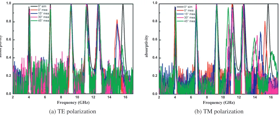
Figure 12(c) illustrates the measured results of the MMA at different polarization angles and the simulated result at 0◦ polarization angle. Under 0◦ polarization angle, the measured absorption rates at 4.01 GHz, 6.68 GHz, 9.23 GHz, 11.17 GHz, 12.57 GHz and 15.02 GHz are 94.35%, 99.35%, 99.27%, 98.33%, 98.35% and 93.58%, respectively. When the polarization angle varies from 0◦ to 45◦, the absorption spectrum remains nearly unchanged at the six absorption frequencies, indicating that the proposed MMA is insensitive to polarization angle. Besides, the slight offset of absorption frequency between the simulation and measurement is caused by manufacturing tolerances and deviation of the permittivity of the substrate. Fig. 13 shows the measured absorptivity as a function of frequency for TE
2 4 6 8 10 12 14 16
0.0 0.2 0.4 0.6 0.8 1.0
absorp
ti
vity
Frequency (GHz)
2 4 6 8 10 12 14 16
0.0 0.2 0.4 0.6 0.8 1.0
absorptivity
Frequency (GHz)
(a) TE polarization (b) TM polarization
and TM polarizations, respectively. In both TE and TM polarization cases, the incident angle ranges from 0◦ to 45◦ in steps of 15◦. For the case of TE polarization, the measured absorption rates remain greater than 87% for different incident angles, except that the absorption peak of mode P6 gradually decreases. For the case of TM polarization, the measured absorption rates of modes P1, P2,P3, P4 and P5 are higher than 94% for different incident angles. For mode P6, the absorption rate drops to 62.35%, and the frequency has a redshift. Thus, the measured results are in good agreements with the simulated ones (see Figs. 7(b) and (c)) at six absorption peaks.
5. CONCLUSION
In this paper, an ultra-thin MMA with the characteristic of polarization-insensitive absorption is obtained by combining the absorption responses of the horizontal-oriented and vertical-oriented MMORs. The proposed MMA, with six obvious absorption peaks at 3.95 GHz, 6.61 GHz, 9.17 GHz, 11.22 GHz, 12.59 GHz, and 15.63 GHz, has the corresponding absorption rates of 97.04%, 99.57%, 99.54%, 98.95%, 99.94% and 99.49%, respectively. The distributions of the surface current and power loss density and the equivalent circuit model are successively investigated to reveal the absorption mechanism. In addition, the influences of several dimension parameters on the performances of the absorber are researched, demonstrating that the frequencies can be optionally modulated, and the absorber can maintain high absorption rate even if there is a deviation in the thickness of the dielectric layer. The dependence of the absorption performances of the proposed MMA on the incident angle and the polarization angle are analyzed, and a good agreement between the measured and simulated results is achieved successfully. Therefore, the proposed MMA with super multiple bands has a great prospect in massive related areas, such as EM filter, sensing and stealth technology.
ACKNOWLEDGMENT
This work was supported by the Young Scientists Fund of the National Natural Science Foundation of China under Grant 61401373 and the Research Fund for the Doctoral Program of Southwest University under Grant SWU111030.
REFERENCES
1. Smith, D. R., W. J. Padilla, D. C. Vier, S. C. Nemat-Nasser, and S. Schultz, “Composite medium with simultaneously negative permeability and permittivity,” Phys. Rev. Lett., Vol. 84, No. 18, 4184–4187, May 2000.
2. Fu, W., et al., “Polarization insensitive wide-angle triple-band metamaterial bandpass filter,” J. Phys. D. Appl. Phys., Vol. 49, No. 28, 285110, Jul. 2016.
3. Lin, F. H. and Z. N. Chen, “Low-profile wideband metasurface antennas using characteristic mode analysis,”IEEE Trans. Antennas Propag., Vol. 65, No. 4, 1706–1713, Apr. 2017.
4. Zhang, L., et al., “Ultrabroadband design for linear polarization conversion and asymmetric transmission crossing X- and K-band,” Sci. Rep., Vol. 6, No. 1, 33826, Dec. 2016.
5. Landy, N. I., S. Sajuyigbe, J. J. Mock, D. R. Smith, and W. J. Padilla, “Perfect metamaterial absorber,” Phys. Rev. Lett., Vol. 100, No. 20, 207402, May 2008.
6. Thummaluru, S. R., N. Mishra, and R. K. Chaudhary, “Design and analysis of an ultrathin X-band polarization-insensitive metamaterial absorber,”Microw. Opt. Technol. Lett., Vol. 58, No. 10, 2481–2485, Oct. 2016.
7. Trung, N. T., D. Lee, H. Sung, and S. Lim, “Angle- and polarization-insensitive metamaterial absorber based on vertical and horizontal symmetric slotted sectors,” Appl. Opt., Vol. 55, No. 29, 8301, Oct. 2016.
9. Bhattacharyya, S. and K. V. Srivastava, “An ultra thin electric field driven LC resonator structure as metamaterial absorber for dual band applications,”International Symposium on Electromagnetic Theory, No. C, 722–725, 2013.
10. Dincer, F., M. Karaaslan, E. Unal, O. Akgol, and C. Sabah, “Multi-band metamaterial absorber: Design, experiment and physical interpretation,” ACES J., Vol. 29, No. 3, 197–202, 2014.
11. Dincer, F., M. Karaaslan, E. Unal, and C. Sabah, “Dual-band polarization independent metamaterial absorber based on omega resoanator and octa-star strip configuration,” Progress In Electromagnetics Research, Vol. 141, 219–231, Jul. 2013.
12. Dincer, F., et al., “Multi-band polarization independent cylindrical metamaterial absorber and sensor application,”Mod. Phys. Lett. B, Vol. 30, No. 8, 1650095, Mar. 2016.
13. Tak, J., Y. Jin, and J. Choi, “A dual-band metamaterial microwave absorber,” Microw. Opt. Technol. Lett., Vol. 58, No. 9, 2052–2057, Sep. 2016.
14. Chen, J., Z. Hu, S. Wang, X. Huang, and M. Liu, “A triple-band, polarization- and incident angle-independent microwave metamaterial absorber with interference theory,”Eur. Phys. J. B, Vol. 89, No. 1, 14, Jan. 2016.
15. Liu, S., et al., “A bi-layered quad-band metamaterial absorber at terahertz frequencies,” J. Appl. Phys., Vol. 118, No. 24, 245304, Dec. 2015.
16. Liu, Y., S. Gu, C. Luo, and X. Zhao, “Ultra-thin broadband metamaterial absorber,”Appl. Phys. A, Vol. 108, No. 1, 19–24, Jul. 2012.
17. Xiong, H., J.-S. Hong, C.-M. Luo, and L.-L. Zhong, “An ultrathin and broadband metamaterial absorber using multi-layer structures,”J. Appl. Phys., Vol. 114, No. 6, 64109, Aug. 2013.
18. Gunduz, O. T. and C. Sabah, “Polarization angle independent perfect multiband metamaterial absorber and energy harvesting application,” J. Comput. Electron., Vol. 15, No. 1, 228–238, Mar. 2016.
19. Ghosh, S., S. Bhattacharyya, Y. Kaiprath, D. Chaurasiya, and K. V. Srivastava, “Triple-band polarization-independent metamaterial absorber using destructive interference,” 2015 European
Microwave Conference (EuMC), 335–338, 2015.
20. Bhattacharyya, S. and K. Vaibhav Srivastava, “Triple band polarization-independent ultra-thin metamaterial absorber using electric field-driven LC resonator,” J. Appl. Phys., Vol. 115, No. 6, 64508, Feb. 2014.
21. Chaurasiya, D., S. Ghosh, S. Bhattacharyya, and K. V. Srivastava, “An ultrathin quad-band polarization-insensitive wide-angle metamaterial absorber,” Microw. Opt. Technol. Lett., Vol. 57, No. 3, 697–702, Mar. 2015.
22. Wang, B.-X., G.-Z. Wang, and L.-L. Wang, “Design of a novel dual-band terahertz metamaterial absorber,” Plasmonics, Vol. 11, No. 2, 523–530, Apr. 2016.
23. Smith, D. R., S. Schultz, P. Markoˇs, and C. M. Soukoulis, “Determination of effective permittivity and permeability of metamaterials from reflection and transmission coefficients,” Phys. Rev. B, Vol. 65, No. 19, 195104, Apr. 2002.
24. Bhattacharyya, S., S. Ghosh, and K. Vaibhav Srivastava, “Triple band polarization-independent metamaterial absorber with bandwidth enhancement at X-band,” J. Appl. Phys., Vol. 114, No. 9, 94514, Sep. 2013.
25. Bian, B., et al., “Novel triple-band polarization-insensitive wide-angle ultra-thin microwave metamaterial absorber,”J. Appl. Phys., Vol. 114, No. 19, 194511, Nov. 2013.
26. Bhattacharyya, S., S. Ghosh, and K. V. Srivastava, “Equivalent circuit model of an ultra-thin polarization-independent triple band metamaterial absorber,” AIP Adv., Vol. 4, No. 9, 97127, Sep. 2014.
27. Baskey, H. B., M. J. Akhtar, A. K. Dixit, and T. C. Shami, “Design, synthesis, characterization and performance evaluation of multi-band perfect metamaterial absorber,”Journal of Electromagnetic Waves and Applications, Vol. 29, No. 18, 2479–2491, Dec. 2015.
29. Zhou, J., E. N. Economon, T. Koschny, and C. M. Soukoulis, “Unifying approach to left-handed material design,”Opt. Lett., Vol. 31, No. 24, 3620, Dec. 2006.
30. Hong, J.,Microstrip Filters for RF/Microwave Applications, 2nd Edition, John Wiley & Sons, Inc., 2011.
31. Xu, H.-X., G.-M. Wang, M.-Q. Qi, J.-G. Liang, J.-Q. Gong, and Z.-M. Xu, “Triple-band polarization-insensitive wide-angle ultra-miniature metamaterial transmission line absorber,”Phys. Rev. B, Vol. 86, No. 20, 205104, Nov. 2012.