Rectangular Horn Antennas with Limiting Plates for Symmetrical
Pattern and Beam Efficiency Improvement
Mahdi Fartookzadeh1, *, Mohammad S. Ghaffarian2, Ali Zamani1, and Reza Fatemi1
Abstract—This paper proposes a horn antenna with limiting plates inside to produce symmetrical pattern in E-plane and H-plane. Sidelobes of the antenna are reduced using the limiting plates, and therefore, the beam efficiency of the antenna is improved up to 90% without changing the antenna dimensions. The antenna dimensions are adjusted to achieve the best beam efficiency. Simultaneously, the reflection coefficient is maintained lower than−15 dB. In addition, it is indicated that this antenna has wide bandwidths without reducing the efficiency and performance of the antenna. Finally, the reflection coefficient is improved to−20 dB without degradation of the antenna performance.
1. INTRODUCTION
Horn antennas are one of the most important antennas in the microwave and millimetre wave applications. An important application for horn antennas is the feed for reflectors including near-field or far-field focused, single reflected or multi-reflected and other constructions [1–6]. In this application and many other applications such as space-fed arrays and lens arrays, beam efficiency is very important since it has influence on the spillover loss. The feed antenna size is also limited since it has effects on the blockage loss. Generally, beam efficiency, aperture efficiency, cross polarization, physical length, and return loss are the main characteristics of horn antennas which are considered as the main purposes of many designers in this area [1]. In addition, each of these parameters should be examined in a certain range of frequency, and hence the bandwidth itself is a characteristic for the antenna.
The improvement of some of these characteristics usually has weakening effects on the others. For example, an interesting method for increasing the beam efficiency of horn antennas is to use corrugated walls. This method increases the antenna size as well and therefore decreases the aperture efficiency [7, 8]. Corrugated horns also have low bandwidth which is improved by replacing the corrugated walls by smooth spline walls in [9]. Another example is the improvement of aperture efficiency in [10] which increases the sidelobe level (SLL) and therefore decreases the beam efficiency. This trade-off can be observed between cross-polarization and aperture efficiency in [11] and [12], as well. The potter horn, described in [13], is the next example that has low sidelobe level and symmetrical pattern with low aperture efficiency. Finally, it is worth to mention that applications of metamaterials are a developing area in designing horn antennas. For example, metamaterials are used for gain enhancement in [14] and for sidelobe reduction in [15].
In this paper, characteristics of an X-band rectangular horn with limiting plates are studied. Employing conductive plates inside the horn antenna is initially invented by Nowakowski and Swartz in [16] for SLL reduction. However, the proposed antenna in [16] does not have symmetrical pattern in both planes, since theE-plane sides of antenna appear larger thanH-plane sides. In addition, reflection coefficient, aperture efficiency and beam efficiency of the antenna are not reported in [16], while they
Received 6 September 2016, Accepted 21 October 2016, Scheduled 9 November 2016 * Corresponding author: Mahdi Fartookzadeh ([email protected]).
Nevertheless, the beam efficiency improvement is obtained with the cost of increasing reflection coefficient up to−15 dB. This reflection coefficient is acceptable for many applications. Therefore, the first antenna is designed and fabricated with the maximum reflection coefficient of −15 dB. However, another version with slightly increased sizes is proposed with decreased reflection coefficient, and the simulation results are reported. The proposed antenna in this paper can be scaled and tuned for any other frequencies.
SLL of a traditional horn antenna with symmetrical radiation pattern cannot increase more than 17.5 dB. This can be examined by changing the aperture sizes and length of a horn antenna and observing the simulation results explicitly. In this paper, we use positive values for SLL, and therefore increasing SLL means sidelobes reduction. However, in next section, it is indicated that the SLL of a horn antenna with symmetrical radiation patterns inE- and H-planes can be increased up to more than 21 dB using limiting plates. Reflection coefficients, gains, and efficiencies are discussed in the third section. Finally, the improvement of reflection coefficient is discussed in the fourth section.
2. ANTENNAS WITH LIMITING PLATES
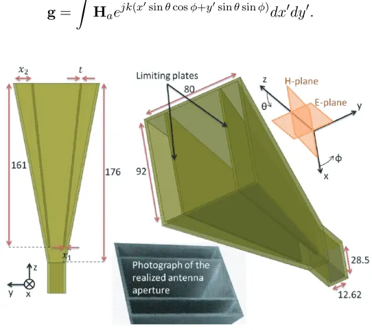
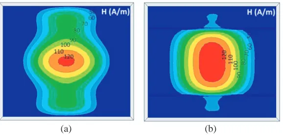
Schematic of a horn antenna with limiting plates is shown in Fig. 1. The plates reduce the field amplitudes on the walls of antenna, and therefore, the E-plane radiation pattern is improved. The amplitudes of magnetic field on the aperture of traditional rectangular horn antenna and the proposed antenna both with 1 W input power are indicated in Fig. 2(a) and Fig. 2(b), respectively. Far-fields can be obtained using 2D Fourier transform of the aperture fields [17],
g=
Haejk(xsinθcosφ+ysinθsinφ)dxdy. (1)
(a) (b)
Figure 2. Amplitudes of magnetic field on the aperture (Ha) of (a) traditional rectangular horn antenna and (b) the horn antenna with limiting plateat 9.5 GHz (x1= 1.1,x2= 15 andt= 2 all in mm).
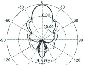
Figure 3. Comparison between H-plane and E-plane radiation patterns of the typical horn antenna (solid line) and the antenna with limiting plates (dashed lines) at 9.5 GHz (x1= 1.1,x2= 15 andt= 2 all in mm).
For example, the electric field of the antenna can be obtained using
EF F ∼= jωμe −jkr
2πr
ˆ
θcosθ(gycosφ−gxsinφ)−φˆ(gysinφ+gxcosφ)
. (2)
The aperture field distribution of conventional horn antennas can be obtained analytically, from the dominant mode of waveguide [1], and as a consequence, the radiated field can be obtained from Eq. (2), while it is not analytically obtainable for the antennas with the plates. However, effects of the field distribution on the far-fields can be recognized from Eq. (1). For example, on the φ= 0 cut plane, phase of the expression in the integral decreases to kxsinθ. Therefore, the integral over small values of kx diminishes on the side-lobes (where θ is large enough); the dominant parts of g are for the large values ofkx, corresponding to the proximity of antenna walls. Similar interpretation can be implied forφ= 90◦ plane. Consequently, the antenna with limiting plates should have smaller sidelobes and minor lobes in E-plane since the field amplitudes are smaller for this antenna near the antenna walls at E-plane. Aperture field distributions of the conventional horn antenna and the antenna with limiting plates are compared in Fig. 2. In addition, radiation patterns of the antennas are compared in Fig. 3. H-plane radiation patterns of the antennas are similar as predicted, and the only difference is in E-plane radiation patterns. It can be observed that E-plane pattern of the proposed antenna is improved significantly.
2 studied as well.
(a) (b) (c)
Figure 4. Parametrical study on the E-plane radiation pattern of antenna at 9.5 GHz; (a) effects of changing x1 from 1.1 mm (solid line) to 2 mm (dashed lines) and 0.5 mm (gray line), (b) effects of changing t from 2 mm (solid line) to 3 mm (dashed lines) and 1 mm (gray line), and (c) effects of changing x2 from 15 mm (solid line) to 18 mm (dashed lines) and 12 mm (gray line).
(a) (b) (c)
Figure 5. Parametrical study on the reflection coefficient of antenna; (a) effects of changing x1 with
t= 2 mm and x2= 15 mm, (b) effects of changing twithx1= 1.1 mm and x2 = 15 mm, and (c) effects of changingx2 withx1= 1.1 mm and t= 2 mm.
(a) (b)
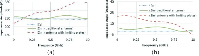
Comparison between input impedances of the traditional horn antenna and the antenna with limiting plates, with similar dimensions is provided in Fig. 6. It can be useful for explaining the degradation of proposed antenna return loss. Amplitudes and angles of the waveguide Z0 and input impedances are indicated in Fig. 6(a) and Fig. 6(b), respectively. Z0 of a waveguide is usually a real number, and the angle is zero as can be seen in Fig. 6(b). It can be observed that the limiting plates lead to higher differences between both amplitudes and angles of the input impedance and Z0. The difference between impedances reduces the impedance matching and as a consequence increases the reflection coefficient.
3. SIMULATION AND MEASUREMENT RESULTS
Simulated reflection coefficient, gain and SLL of the antenna in Fig. 1 are indicated in Fig. 7 from 8 GHz to 11 GHz. It can be observed that the sidelobe is indeed at higher level than a traditional horn antenna. According to the simulation results, the proposed antenna has good performance throughout the X-band frequency. Simulated and measured radiation patterns of the proposed antenna are indicated in Fig. 8 at three frequencies, 9.2, 9.5 and 9.8 GHz. TheH-plane radiation patterns do not have significant difference from the conventional horn antenna, and the main improvement is on theE-plane patterns as explained. It can be observed that the minor lobes are reduced compared with the radiation pattern of
Figure 7. Simulated results of the antenna from 8 GHz to 11 GHz; reflection coefficient, Gain and SLL.
(a)
(b)
Figure 9. Simulated and measured results of the antenna. (a) Reflection coefficients and Gain. (b) Aperture and beam efficiency.
traditional rectangular horn antenna in Fig. 3. The reduction of the minor lobes leads to improvement of the antenna beam efficiency as indicated in Fig. 9(a). Beam efficiency is obtained using
Beam efficiency =
2π
0
θ1(φ)
0
P(θ, φ) sinθdθdφ
Prad (3)
where θ1(φ) is θ of the 10 dB lower than maximum gain at the givenφ, and Prad is the total radiated power. It should be noted that the aperture efficiency and beam efficiency of a regular rectangular horn antenna are about 80%. Therefore, beam efficiency of the antenna is improved up to 90% without reduction of the aperture efficiency. Measured beam efficiency is not reported in Fig. 9(a). However, one can recognize from the agreement of simulated and measured radiation patterns in Fig. 8 that the beam efficiency of realized antenna should be similar to the simulations.
In addition, we have another trade-off between beam efficiency and reflection coefficient that can be controlled by the positions of the limiting planes. In particular, beam efficiency can be improved by reducing the separation between small sides of the limiting plates and the antenna walls. However, it will increase the reflection coefficient as well. The antenna with limiting plates with 1.1 mm separation and other dimensions indicated in Fig. 1 has better than −15 dB reflection coefficients. Simulated and measured reflection coefficients are indicated in Fig. 9(b). In addition, the simulated and measured gains are higher than 18 dB between 9 and 10 GHz. It should be mentioned that the proposed antenna has wide bandwidth, and the improvements in the beam efficiency are not limited between 9 and 10 GHz. This is an advantage over narrow-band antennas such as corrugated horns.
4. IMPROVEMENT OF REFLECTION COEFFICIENT
Reflection coefficient of the proposed antenna can be improved by increasing the antenna length. Schematic of the modified antenna is indicated in Fig. 10. Aperture size is set to 97 mm×78 mm. However, it does not change the aperture efficiency significantly. The gain and reflection coefficient are indicated in Fig. 11 from 8 GHz to 11 GHz. It can be observed that the reflection coefficient is improved up to less than −20 dB from 8.2 GHz to 9.7 GHz. Radiation pattern of the antenna is indicated in Fig. 12. The symmetrical pattern and SLL are not influenced significantly. In addition, it can be observed in Fig. 13 that the radiation patterns have good performance from 8 GHz to 11 GHz as well.
Figure 10. Schematics of the rectangular horn antenna with improved reflection coefficient (Dimensions in mm).
Figure 11. Simulated results of the modified an-tenna from 8 GHz to 11 GHz; reflection coefficient compared with previous antenna and Gain.
Figure 12. E-plane andH-plane radiation patterns of the modified antenna at 9.5 GHz (dashed lines are forE-plane and solid lines are forH-plane).
Figure 13. E-plane and H-plane radiation patterns of the modified antenna at various frequencies (dashed lines are for E-plane and solid lines are forH-plane).
Beam Efficiency (%) 89.6 90.3 89.8 90.5 89.6 89.2
|S11|(dB) −15.5 −17.5 −15.5 −20.7 −22.7 −19.2
E-plane Beam-width (deg.) 41.2 40.4 38 41.4 39.4 38
H-plane Beam-width (deg.) 41.8 40.4 39.2 39.8 38.6 37.2
is 74% at the centre frequency while the proposed antennas have more than 77% aperture efficiency as can be observed in Table 1. Similar comparisons with other horn antennas indicate that the proposed antennas have better performance in comparison with most available structures in the literature.
5. CONCLUSIONS
An important application for the horn antennas is the feed antenna for reflectors. In this application and many other applications, the beam efficiency is very effective since it has significant effects on the spillover loss. Also we have limitations in size of the feed antenna since it has effects on the blockage loss. Therefore, the valuable result of this paper is the improvement of the beam efficiency without increasing the antenna size. A horn antenna with limiting plates is proposed with high beam efficiency without reducing the aperture efficiency. Simulation results are validated by measured ones between 9 and 10 GHz. In addition, it is indicated that this antenna can be used for wider bandwidth and demonstrated by further simulation results for 8 to 11 GHz. Moreover, an improved antenna with fewer reflections is proposed without losing the performance.
REFERENCES
1. Balanis, C. A., Antenna Theory Analysis and Design, John Wiley & Sons, New York, 2005. 2. Dehdasht-Heydari, R., H. R. Hassani, and A. R. R. Mallahzadeh, “Quad ridged horn antenna for
UWB applications,” Progress In Electromagnetics Research, Vol. 79, 23–38, 2008.
3. Mallahzadeh, A. R. and F. Karshenas, “Modified tem horn antenna for broadband applications,”
Progress In Electromagnetics Research, Vol. 90, 105–119, 2009.
4. Agastra, E., G. Bellaveglia, L. Lucci, R. Nesti, G. Pelosi, G. Ruggerini, and S. Selleri, “Genetic algorithm optimization of high-efficiency wide-band multimodal square horns for discrete lenses,”
Progress In Electromagnetics Research, Vol. 83, 335–352, 2008.
5. Fartookzadeh, M. and S. H. MohseniArmaki, “Dual-band reflection-type circular polarizers based on anisotropic impedance surfaces,” IEEE Transactions on Antennas and Propagation, Vol. 64, 826–830, Feb. 2016.
6. Fartookzadeh, M. and S. H. MohseniArmaki, “Millimeter wave near field focusing cassegrain reflector antennas,”Journal of Applied Electromagnetics, Vol. 2, 41–49, 2015 (in Persian), available: http://journals.ihu.ac.ir/index.php/elemag/article/view/8831.
7. Lawrie, R. and L. Peters, “Modifications of horn antennas for low sidelobe levels,” IEEE Transactions on Antennas and Propagation, Vol. 14, 605–610, Sep. 1966.
9. Granet, C., G. L. James, R. Bolton, and G. Moorey, “A smooth-walled spline-profile horn as an alternative to the corrugated horn for wide band millimeter-wave applications,”IEEE Transactions on Antennas and Propagation, Vol. 52, 848–854, Mar. 2004.
10. Bird, T. S. and C. Granet, “Optimization of profiles of rectangular horns for high efficiency,”IEEE Transactions on Antennas and Propagation, Vol. 55, 2480–2488, Sep. 2007.
11. Deguchi, H., M. Tsuji, and H. Shigesawa, “Compact low-cross-polarization horn antennas with serpentine-shaped taper,” IEEE Transactions on Antennas and Propagation, Vol. 52, 2510–2516, Oct. 2004.
12. Ruggerini, G., “A compact circular horn with high efficiency,”Proc. of the 4th European Conf. on Antennas and Propagation. IEEE Conf., 1–3, Barcelona, Spain, 2010.
13. Potter, P. D., “A new horn antenna with suppressed sidelobes and equal bandwidths,” Jet Propulsion Laboratory, California Institute of Technology, CA, 1963.
14. Xiao, Z. and H. Xu, “Low refractive metamaterials for gain enhancement of Horn Antenna,” J. Infrared MilliTerahz Waves, Vol. 30, 225–232, Dec. 2008.
15. Qi, M. Q., W. X. Tang, H. F. Ma, B. C. Pan, Z. Tao, Y. Z. Sun, and T. J. Cui, “Suppressing side-lobe radiations of horn antenna by loading metamaterial lens,” Nature Scientific Reports, Vol. 5, 9113, Mar. 2015.
16. Nowakowski, M. and E. Swartz, “Low sidelobe horn antenna with internal conductive plates,” U.S. Patent 3,-171,129, Feb. 23, 1965.