Western University Western University
Scholarship@Western
Scholarship@Western
Electronic Thesis and Dissertation Repository
10-10-2019 1:00 PM
Feasibility and Reliability of a Commercially Available
Feasibility and Reliability of a Commercially Available
Stretch-Sensitive Sensor for Neck Movement
Sensitive Sensor for Neck Movement
Iyad Al-Nasri
The University of Western Ontario
Supervisor Walton, David M.
The University of Western Ontario
Graduate Program in Health and Rehabilitation Sciences
A thesis submitted in partial fulfillment of the requirements for the degree in Master of Science © Iyad Al-Nasri 2019
Follow this and additional works at: https://ir.lib.uwo.ca/etd Part of the Rehabilitation and Therapy Commons
Recommended Citation Recommended Citation
Al-Nasri, Iyad, "Feasibility and Reliability of a Commercially Available Stretch-Sensitive Sensor for Neck Movement" (2019). Electronic Thesis and Dissertation Repository. 6574.
https://ir.lib.uwo.ca/etd/6574
This Dissertation/Thesis is brought to you for free and open access by Scholarship@Western. It has been accepted for inclusion in Electronic Thesis and Dissertation Repository by an authorized administrator of
Abstract
The ability to move the neck is usually a good indicator of neck health. However, the tools currently available to measure neck range of motion rely on gravity and the clinician's ability to accurately line the instruments on specific landmarks of the body. This study explored whether a commercially available wearable sensor, C-Stretch® that is flexible and lightweight can capture the functional performance of cervical motion across testing sessions. Furthermore, an assessment of the C-Stretch® against Aurora NDI, an electromagnetic tracking system was explored to determine the feasibility of transforming raw capacitance data into degrees of motion. Finally, a survey explored the user’s experience with C-Stretch®. The C-Stretch® was able to monitor cervical motion across testing with good reliability for the Bag-Lift and poor reliability for the Bag-Slide and Star task (ICC2,1 0.57, 0.39, 0.37), respectively. The systems accuracy and agreement
for rotational neck motion were evaluated. The C-Stretch® showed high correlation (r = 0.90-0.99, p < 0.01) for areas of overlap and was accurate for both sessions with average RMSE values of 5.06° (95% C.I = 0.30° to 10.10°) for the first session and 5.34° (95% C.I = 0.10° to 10.79°) for the second session with respect to the electromagnetic tracking system. Overall, users tolerated the C-Stretch® and did not find it uncomfortable. This study highlights the feasibility of using wearable stretch sensors that are light, unobtrusive and comfortable for assessing functional performance of the cervical spine.
Keywords
Summary for Lay Audience
The ability to move the neck is usually a good indicator of neck health. However, the tools currently available to measure neck range of motion rely on gravity and the clinician's ability to accurately line the instruments on specific landmarks of the body. The current study explores the use of a commercially available wearable stretch-sensitive sensor (C-Stretch®) along the sides of the neck of participants while they perform standardized tasks in a lab environment. The results were then compared against a gold-standard tracking system to assess whether this tool can be used to measure rotational neck movement. The results indicate that C-Stretch was able to monitor neck motion across testing sessions with good reliability for the first task, Bag-Lift and poor reliability for the second and third tasks, Bag-Slide and Star task (ICC2,1 0.57, 0.39, 0.37), respectively. For
Acknowledgements
In the name of Allah, the Most Gracious, the Most Merciful
First and foremost, all thanks to God. All praise due to God. It is with His compassion and mercy I have completed this master’s thesis.
I want to acknowledge the Natural Sciences and Engineering Research Council (NSERC) of Canada for supporting my work through the Alexander Graham Bell–Canada Graduate Scholarship-Master’s (CGS-M).
When starting my project, I was very comforted to find an accepting and warm environment in the faculty of Health Sciences. I want to thank my P.I.R.L family. I am so happy I had the chance to meet all of you. You guys made my master’s thesis experience one of a kind. A special thank you goes to all of you for always believing in me and supporting me along this journey. A sincere thank you goes out to Mr. Lee, Mr. Fakhereddin and Mr. Salim for your kind words and guidance along the way.
Parts of the project could not have materialized without the collaborations and support from the Wearable Biomechatronic Lab and the Organic Mechatronics & Smart Materials Lab. I want to acknowledge the help of Yue Zhoe for his support with data processing. I also want to acknowledge Rami Abu Shammah for his contributions and collaboration in the development and evaluation of our soft wearable sensor.
I would also like to express my deepest appreciation to my advisory committee members, Dr. Ana Luisa Trejos, and Dr. Aaron D. Price, whose guidance, contributions, and experience were invaluable in guiding the project. I want to acknowledge and render many sincere thanks to my supervisor Dr. David M. Walton for all his time and patience during the past two years and throughout the writing process of this thesis. Thank you for believing in me and for allowing me to grow as a transdisciplinary researcher. Your advice and knowledge of both research and life have been invaluable.
Table of Contents
ABSTRACT ... I SUMMARY FOR LAY AUDIENCE ... II ACKNOWLEDGEMENTS ... III LIST OF TABLES ... VII LIST OF FIGURES ... VIII
CHAPTER 1 ... 1
INTRODUCTION ... 1
1.1 NECK PAIN CLASSIFICATION ... 1
1.2 PREVALENCE ... 2
1.3 CERVICAL ANATOMY ... 3
1.4 RANGE OF MOTION ... 4
1.5 TRADITIONAL MEASUREMENT TOOLS OF ROM ... 4
1.5.1 Tape Measure ... 5
1.5.2 Inclinometer ... 5
1.5.3 CROM Device & Universal Manual Goniometer ... 6
1.6 3D-MOTION TRACKING SYSTEMS FOR ROM ... 7
1.6.1 Optoelectronic Measurement Systems ... 7
1.6.2 Electromagnetic Measurement System ... 8
1.6.3 Inertial Measurement Unit Systems ... 9
1.7 ANEW APPROACH TO CROM ... 10
1.7.1 Electronic Textiles ... 11
1.7.2 Stretch-Sensitive Sensors ... 11
1.8 OBJECTIVES ... 14
1.9 THESIS OUTLINE ... 14
2 CHAPTER 2 ... 15
METHODS & PROTOCOL ... 15
2.1 POSITIONING AND ORIENTATION OF C-STRETCH® ... 15
2.2 POSITIONING OF THE EMTSSENSOR COIL ... 17
2.3 ADHESION OF EMTS AND C-STRETCH ... 18
2.4 PROTOCOL ... 18
2.4.1 CALIBRATION PHASE ... 19
2.4.2 PERFORMANCE PHASE ... 19
2.5 DATA PROCESSING ... 22
2.5.1 Objective 1 ... 22
2.5.2 Objective 2 ... 23
2.5.3 Objective 3 ... 24
2.6 STATISTICAL ANALYSIS ... 24
2.6.1 Objective 1 ... 24
2.6.2 Objective 2 ... 25
2.6.3 Objective 3 ... 26
2.7 SAMPLE SIZE ESTIMATION ... 26
3 CHAPTER 3 ... 27
3.1 OBJECTIVE 1 ... 27
3.2 OBJECTIVE 2 ... 35
3.3 OBJECTIVE 3 ... 38
4 CHAPTER 4 ... 39
DISCUSSION ... 39
5 CHAPTER 5 ... 45
CONCLUSION ... 45
5.1 FUTURE DIRECTIONS ... 45
5.2 CONTRIBUTIONS ... 46
REFERENCES ... 48
APPENDIX A ... 59
APPENDIX B ... 60
APPENDIX C ... 62
ETHICS APPROVAL ... 63
PHOTO RELEASE FORM ... 64
List of Tables
TABLE 1.SUMMARY OF ACTIVE ROM FROM HEALTHY PEOPLE RANKED BASED ON AGE. ... 4
TABLE 2.DESCRIPTIVE SUMMARY (MEANS, STANDARD DEVIATION,95% CONFIDENCE INTERVALS) OF NECK MOVEMENTS FROM 28 PARTICIPANTS FOR EACH PERFORMANCE TASK, BY SENSOR SIDE AND TESTING SESSION. ... 27
TABLE 3. AVERAGE RMSE FROM BOTH SESSIONS FOR LEFT AND RIGHT ROTATIONS FROM ALL
PARTICIPANTS. ... 36
TABLE 4.RESPONSE FREQUENCY OF USERS EXPERIENCE AND COMFORT USING C-STRETCH®.(0=
List of Figures
FIGURE 1.TAPE MEASURE USED FOR ROM. 5
FIGURE 2.DIGITAL INCLINOMETER USED FOR ROM. 6
FIGURE 3.OPTOELECTRONIC MOTION CAPTURE SETUP.OBTAINED FROM WWW.OPTITRACK.COM 8
FIGURE 4.AURORA NDI, AN ELECTROMAGENTIC TRACKING SYSTEM. 9
FIGURE 5.EXAMPLE OF AN IMU WITH AN EMBEDDED ACCELEROMETER, GYROSCOPE AND
MAGNETOMETER. 10
FIGURE 6.THE BASIC STRUCTURE OF A DIELECTRIC ELASTOMER SENSOR. 12
FIGURE 7.UNSTRAINED DIELECTRIC ELASTOMER SENSOR WITH A STABLE CAPACITANCE AND STRAINED
DES WITH HIGHER CAPACITANCE READING. 13
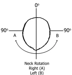
FIGURE 8.ROTATION OF THE NECK ALONG THE HORIZONTAL PLANE. 14
FIGURE 9.MOVEMENT PARTICIPANTS WERE ASKED TO PRODUCE IN THE THREE CARDINAL PLANES. 16
FIGURE 10.PLACEMENT AND ORIENTATION OF THE C-STRETCH® ALONG THE SCM. 16
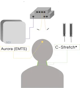
FIGURE 11.SENSOR POSITIONS FOR BOTH SYSTEMS. 17
FIGURE 12.DESK AND SHELF SETUP WITH BEANBAGS,TASK 1. 20
FIGURE 13.DESK AND SHELF SETUP FOR TASK 2. 21
FIGURE 14.THE FIVE-POINT STAR USED FOR TASK 3.ARROW INDICATING A COUNTERCLOCK MOTION
PARTICIPANTS OBSERVED. 22
FIGURE 15.AVERAGE MOVEMENT DATA OF ALL PARTICIPANTS (N=28) FOR THE RIGHT SENSOR FROM BOTH SESSIONS WITH 95% CONFIDENCE INTERVALS FOR BAG-LIFT (TASK 1). 29
FIGURE 16.AVERAGE MOVEMENT DATA OF ALL PARTICIPANTS (N=28) FOR THE RIGHT SENSOR FROM BOTH SESSIONS WITH 95% CONFIDENCE INTERVALS FOR BAG-SLIDE (TASK2). 30
FIGURE 17.AVERAGE MOVEMENT DATA OF ALL PARTICIPANTS (N=28) FOR THE RIGHT SENSOR FROM BOTH SESSIONS WITH 95% CONFIDENCE INTERVALS FOR THE STAR (TASK 3). 31
FIGURE 18.BLAND ALTMAN PLOT OF AGREEMENT BETWEEN SESSION 1 AND SESSION 2 FOR THE BAG
-LIFT TASK.DASHED HORIZONTAL LINE REPRESENTS THE MEAN DIFFERENCE (5.03) AND THE RED LINES REPRESENT THE LOWER AND UPPER LIMITS OF AGREEMENT (-11.25 TO 21.33). 32
FIGURE 19. BLAND ALTMAN PLOT OF AGREEMENT BETWEEN SESSION 1 AND SESSION 2 FOR THE BAG
-SLIDE TASK.DASHED HORIZONTAL LINE REPRESENTS THE MEAN DIFFERENCE (5.68) AND THE RED LINES REPRESENT THE LOWER AND UPPER LIMITS OF AGREEMENT (-23.95 TO 35.31). 33
FIGURE 20.BLAND ALTMAN PLOT OF AGREEMENT BETWEEN SESSION 1 AND SESSION 2 FOR THE STAR TASK.THE DASHED HORIZONTAL LINE REPRESENTS THE MEAN DIFFERENCE (7.21), AND THE RED LINES REPRESENT THE LOWER AND UPPER LIMITS OF AGREEMENT (-15.95 TO 39.78). 34
FIGURE 21.LINE OF FIT PLOT FROM THE LEFT SIDE OF THE NECK FOR PREDICTED MOVEMENT FROM CAPACITANCE (INDEPENDENT) TO DEGREES (DEPENDENT) USING EMTS AFTER PERFORMING
LINEAR REGRESSION. 36
FIGURE 22.REPRESENTATIVE ROTATIONAL MOVEMENT DATA FROM ONE PARTICIPANT FOR BOTH
C-STRETCH® SENSORS AND THE EMTS SENSOR.THE VALLEYS ARE MAXIMUM ROM FOR LEFT TURNS WITH 0 DEGREES BEING NEUTRAL (HEAD FACING FORWARD) AND PEAKS REPRESENTATIVE OF
Chapter 1
Introduction
The spinal column is the body’s main support structure divided into three parts; cervical, thoracic and lumbar spine. Of the three parts, the cervical spine is composed of seven vertebrae and allows the greatest freedom of movement. The cervical spine (neck) can move in all three cardinal planes of motion (frontal, sagittal, and horizontal) and, among other functions, the neck bears the load of the head for maintaining an upright posture. The cervical spine also serves as a layer of protection of several sensitive structures such as the cervical portion of the spinal cord and brainstem, the autonomic cervical ganglia, arterial supply to the brain, and is chiefly responsible for orienting the sense organs of the head towards environmental stimuli. As a result, the neck endures many daily strains and dysfunction in this region is responsible for one of the highest burdens of global disability [1]. With a peak burden in middle-age [1,2], the United States spent an estimated 87.6 billion dollars in 2013 on health care costs associated with ambulatory care, inpatient care and pharmaceuticals for low back and neck pain [3]. Furthermore, the tools currently used to assses neck mobility are limted to clinical settings, and use straight-plane movements that are not representative of day-to-day performance in the real-world [4]. Therefore, the motivation for this thesis is the inability to accurately capture cervical mobility in real-time. As a result, the purpose of this thesis was to explore whether a commercially available sensor can capture functional craniocervical movements in real-time with an emphasis on reliability.
1.1
Neck Pain Classification
on symptom and pathology. A classification of Grade I and Grade II suggest that there are no symptoms or signs of major structural damage and disease, with Grade II neck pain is severe enough to interfere with daily life and requires the intervention of pain relief. Grade III and Grade IV differ from each other in that Grade III there are no signs or symptoms of major disease and damage, but neurological deficits are apparent. Grade IV differs from the other classifications in that there are signs and symptoms that support structural disease and damage (e.g. fracture or dislocation) and therefore require immediate intervention [5]. Recently, MacDermid et al. have added to this definition by classifying pain qualitatively into a seven-axis model to further classify pain. This incorporates the same model used by The Neck Pain Task Force; 1) Context , 2) Sample, 3) Severity, 4) Duration, 5) Pattern, but separating severity into two distinct sub-axes: 1) Symptom Severity and 2) Disability [6]. Of these axes, the nature of neck pain is usually described with respect to the symptom (i.e. localized to the neck, localized to the neck and shoulder, a combination of head and neck, shoulder and arm symptoms and so forth), severity (i.e. none, mild, moderate, severe), duration (i.e. transitory, short, long), the temporal pattern (i.e., a single episode, recurrent, persistent-stable, persistent-unstable) and effect on daily activity (i.e. basic hygiene, going to work, or participating in leisure activities)[5,6].
1.2
Prevalence
1.3
Cervical Anatomy
The cervical spine consists of seven vertebrae that articulate through seven intervertebral discs and seven pairs of zygoapophyseal (facet) joints. Some authors also recognize the existence of accessory or uncinate joints at the lateral portions of the vertebral body that are unique to the cervical spine [14,15]. The articulations are supported by 26 muscles in the neck (ten pairs of two and two sets of three). This provides the neck with the ability to move through multiple degrees of freedom (DOF), making the neck function collectively as a complex joint with multiple axes that are usually bound by the lower edge of the occiput cranially and the upper edge of the 1st thoracic vertebral body caudally. The first
two vertebrae commonly referred to as the atlas (C1) and axis (C2) are considered atypical compared to the 3rd through 7th vertebrae, owing to their unique articulations and
ligaments including the presence of an odontoid process on C2 and the lack of easily identifiable disc between C1 and C2. The cervical musculature can be split down the anatomical midline into left and right groups, meaning that most movements that occur at the cervical spine are a result of coordinated symmetrical or asymmetrical paired muscle contractions and relaxation. Sagittal plane flexion-extension movements are a direct result of paired muscle contractions of both sides of the neck leading to the bending of the upper cervical spine (C1-C5). Cervical rotation in the horizontal plane occurs through reciprocal contraction of an agonist on one side and antagonist on the other, resulting in a coupled rotation/lateral flexion of the neck. Left and right flexion (side bend) in the frontal plane similarly occur through coordinated asymmetrical contraction/relaxation of key muscle groups on each side of the neck.
multiplanar orientation of the articular surfaces of the vertebrae, the motion of the neck during rotation or lateral flexion rarely occur in a single plane of motion [17–21].
1.4
Range of Motion
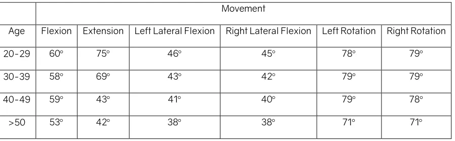
According to the dictionary of Modern Medicine, range of motion is the amount a joint can move as a result of the articular surfaces, ligaments and muscle contractions [20]. Normal values for the range of motion (ROM) are key identifiers for clinicians when discerning deficits, and assessing and monitoring joint health in people. In the literature, many studies have defined the normal active range of motion across many different age groups [22–25]. However, as described above, the complex multiplanar movements of the neck can make the evaluation of mobility difficult for clinicians. Table 1 shows normal values for 400 aspymptomatic people (males and females) for active cervical range of motion ranked by age groups with no difference between the sexes as reported by Swinkels et al., (2014) [22].
Table 1. Summary of active ROM from healthy people ranked based on age.
Movement
Age Flexion Extension Left Lateral Flexion Right Lateral Flexion Left Rotation Right Rotation 20-29 60° 75° 46° 45° 78° 79°
30-39 58° 69° 43° 42° 79° 79°
40-49 59° 43° 41° 40° 79° 78°
>50 53° 42° 38° 38° 71° 71°
1.5
Traditional Measurement Tools of ROM
It is worth noting as with any measurement tool, especially when dealing with a clinical measurement tool, reliability (the degree to which measurements are stable in repeated testing under otherwise stable conditions) and validity (the degree to which the instrument measures the intended construct) are important properties that need to be understood in order to interpret patient results accurately. An instrument that is not reliable or valid can lead to misinformed decisions regarding diagnosis, treatment, prognosis, and evaluation of treatment effectiveness [26].
1.5.1
Tape Measure
A tape measure is a simple and easy to use tool that can assess CROM. It is attractive for clinicians for its small size, ease of use and low cost. The use of a tape measure relies on bony landmarks and measures motion via distance between landmarks rather than degrees. Measurements can be obtained in all of the three planes of motion (frontal, sagittal, and horizontal plane) with some variation in methods for measuring the rotation of the cervical spine in the transverse plane [27,28]. However, interobserver and intraobserver reliability for the tape measure has been poor to moderate [29]. Studies investigating the tape measure suggest that this method is least likely to capture accurate estimates of cervical range of motion [26,28,30].
1.5.2
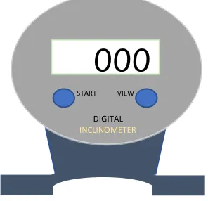
Inclinometer
An inclinometer measures angles of slope (degrees of incline) in relation to gravity. The digital form of an inclinometer uses microelectromechanical sensors to align to gravity, while analog versions use simple weighted plumb lines or ball bearings. Often, the range
of motion is measured while the instrument is placed on top of the person's head under careful instruction from a clinician to perform CROM movements while keeping the thorax still [31]. Studies evaluating reliability and validity are inconclusive with some endorsing the inclinometer as a reliable tool [31,32] and other studies suggesting otherwise [26,31,33,34]. Furthermore, the reliance on orientation to gravity means that not all planes of motion can be tested without changing the orientation of the body (e.g. from sitting up to lying down). Bush et al., (2000) described the inclinometer as an inconsistent device in that they are unable to discriminate coupled movements of the cervical spine, particularly to the motions associated with lateral flexion and rotation [31].
1.5.3
CROM Device & Universal Manual Goniometer
The CROM device is much like the inclinometer above, composed of a plastic frame made to sit on the bridge of the nose and strapped around the head and across the chin. Attached to this frame are three independent, usually ball-bearing inclinometers that track the head with reference to gravity [35]. Although reported to be reliable for measuring CROM in whiplash-associated disorder populations [27], some limitations exist in regards to cost and patient comfort, in addition to the limitations discussed above for inclinometers. A manual goniometer is essentially a transparent plastic protractor with two extended arms. The manual goniometer is different than the CROM device since it does not need to be strapped on the person to obtain ROM. Instead, one stationary arm
000
START VIEWDIGITAL INCLINOMETER
is lined up along a stationary body axis such as the trunk, and one moveable arm is lined up with a landmark on the head (e.g. the nose or ear line) to obtain degrees of ROM. Some studies have found the manual goniometer to be less accurate due to rater consistency, proper alignment with anatomical landmarks and the need to identify a neutral starting head position [36,37]. From de Konings [38] and Williams [30] review of these two instruments alongside the inclinometer and tape measure they suggest that these tools for measurement of cervical range of motion are at best ‘good’ estimates of CROM.
1.6
3D-Motion Tracking Systems for ROM
Given the complex motions of the cervical spine, a 3-dimensional motion capture system arguably provides a more realistic quantification of mobility, mainly as it can track movement through multiple planes simultaneously and is not bound by the orientation to gravity. Presently, different strategies have been proposed to evaluate the range of motion in 3D. These newer strategies involve the use of 3D-motion tracking systems, which include optoelectronic measurement systems, electromagnetic measurement systems and inertial measurement units.
1.6.1
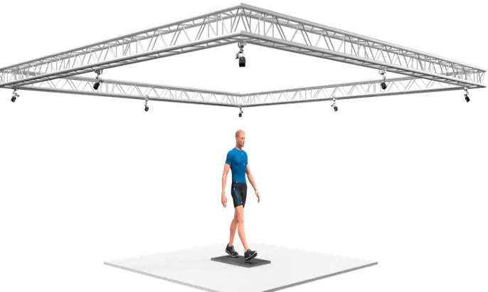
Optoelectronic Measurement Systems
Another emerging trend that could be classed as an optoelectronic tracker is Virtual Reality (VR) headsets. While different hardware exists, many commercially available VR headsets use a similar setup of cameras that track IR emitting diodes on the head-mounted displays (HMD), such as the Oculus Rift® (Facebook Inc., Menlo Park CA) and the HTC Vive® (HTC Inc., Seattle WA). This type of system allows the user to interact with virtual objects or to complete objectives in a virtual world to illicit real-world motions that can be tracked [42]. The limitation with such a system is the discrepancy caused by lag, which is the delay between a performed action and its execution, usually resulting in nausea [43], dizziness [44], and motion sickness [45,46] in some users. Additionally, the loss and regaining of tracking is a source of inaccuracy for capturing movements that are seen with a line of sight dedicated 3D multi-camera IR systems[47].
1.6.2
Electromagnetic Measurement System
Electromagnetic tracking systems use wired sensor coils that work in proximity with a referenced electromagnetic field generator. The field generator emits electromagnetic signals to locate the position and orientation of the sensor coils. Aurora NDI is an example of this type of system. Unlike the optoelectronic systems, electromagnetic systems do not require a direct line of sight to track the position and orientation of the sensors coil [42].
This makes for an ideal system for out of sight motion tracking, as seen in tracking medical instruments during minimally invasive medical surgeries [42]. While these systems overcome some of the limitations with optical tracking systems, they require the subject to remain within proximity to the magnetic sensor preventing the capture of larger functional movements. For example, the Aurora NDI is only capable of capturing 3D-motion within a volume of 50cm by 50cm [48]. These tracking systems are also cost-prohibitive for routine clinical use and are sensitive to ferromagnetic materials in the environment that can add noise to the signal [49].
1.6.3
Inertial Measurement Unit Systems
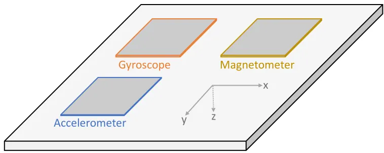
An inertial measurement unit (IMU) is a device that consists of one or more motion sensors in a single device. They often consist of accelerometers that measure linear accelerations, gyroscopes that measure angular velocity, and at times incorporate the use of magnetometers that determines the orientation of the IMU with respect to earth’s magnetic field [50,51]. In contrast to stationary optical or electromagnetic systems, IMUs are portable, unobtrusive, can be worn, and are not limited or tethered to a benchtop external sensor. In the literature, IMUs have been used to evaluate CROM. Zhou et al., (2018) used a single IMU to differentiate between impaired and healthy necks via circumduction movements measured using a head-worn wireless accelerometer [50]. However, limitations include the sensitivity of accelerometers to gravity, meaning that a reference sensor is generally required for the accurate range of motion calculations.
NDI
IMU’s are also sensitive to interference by ferromagnetic materials because of the magnetometers, require frequent battery recharging, and often require complex computational models and algorithm development to make sense of the data.
1.7
A New Approach to CROM
Wearable sensors hold the potential to function as valid metrics of ecological ‘real-world’ cervical mobility in that they are not constrained to a clinic or laboratory environment. Wearable sensors are seeing an increase in popularity in health and rehabilitation as clinicians are finding value in more real-world metrics of mobility or vital signs beyond those captured during a 15-minute clinic visit [52,53]. They can also provide wearers and healthcare providers near-instantaneous feedback, in real-time, without complicated equipment or setup offering the potential for more personalized and on-demand health recommendations.
Commercially there are many examples of wearable devices that range in shape from smartwatches to armbands, smart clothing, jewellery, and eyeglasses amongst others. A common example of this is the increasing trend for wearable activity monitoring devices such as the Fitbit® (Fitbit Inc. San Francisco CA), Apple watch® (Apple Inc. Cupertino CA),
Accelerometer
Gyroscope Magnetometer
x
y z
and Samsung Gear® (Samsung Inc. Seoul South Korea) wrist-worn devices. Most of these devices use IMUs to detect motion with a purpose to provide the user with ‘real-time’ feedback about motion and activity, and some can be taught through algorithms and sensors to differentiate types of activity (e.g. walking vs. running, vs. climbing stairs). Other metrics can be captured depending on the sensors embedded within, including heart rate, skin temperature, and blood oxygenation [54]. A review of wearable and implantable sensors for biomedical applications by Koydemir and Ozcan [55] demonstrated the breadth of embedded wearable devices for health monitoring. They found that there are many more wearable devices that can be donned on various body parts, from anywhere and as small as an earring on the ear to socks on the feet with the ability to monitor activity levels, blood oxygen saturation levels, calories burned, body temperature, sleep quality/pattern and monitoring.
1.7.1
Electronic Textiles
Wearables have also become increasingly integrated, embedded and implanted into everyday items in a way that is intended to not interfere with day-to-day activities. Further technological advancements in material science have enabled the development of wearable technology that sees embedded electronics on flexible substrates that are then put into fabrics allowing for sensing capabilities. As a result, e-fabrics have gained attention for their ability to monitor parameters such as heart rate, respiration rate, skin temperature and human movement [55,56]. An example, is the Smart Sock introduced by Alpha-FitGmbH (Wertheim, Germany) [57], that can measure the dynamic pressures across the entire foot as a result of loading caused by walking. This allows clinicians to then customize patient-specific shoes for monitoring abnormal forces on the feet of those who suffer from diabetes-related sensory loss. Fabrication is achieved by weaving or printing conductive components onto the fabric and then sensing the changes in the resistance of the material as it deforms.
1.7.2
Stretch-Sensitive Sensors
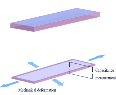
lightweight, stretchable, can withstand large strains and are relatively low cost [58–61]. DES are non-intrusive and can be oriented or designed as well as integrated into fabrics in a way that they are responsive to multiple degrees of freedom at once [59]. DES are based on electroactive polymers (EAP) which are comprised of a soft insulating silicone amongst other soft materials. DES function based on the principle of a parallel plate capacitor [62]. In this case, the parallel plate capacitor consists of a soft dielectric material sandwiched between stretchable electrodes, as seen in Figure 6.
From this parallel capacitor, the capacitance can be recorded, which is the electrical potential of a system. In the case of a parallel plate system, when the distance between the two plates decreases or increases as a result of mechanical deformation, the capacitance changes. Therefore, mechanical work can transduce a change in the electrical signal [58,62]. This allows for a DES to act as a stretch/strain sensor. Capacitance can be defined as the change proportional to the area of overlap and inversely proportional to the separation between the two conducting layers. As thickness decreases, surface area increases, and as a result, a higher value of capacitance (Figure 7)[61]. Capacitance can be calculated by the equation:
Figure 6. The basic structure of a dielectric elastomer sensor.
Where ɛ% is the vacuum permittivity (the measure of the materials ability to store an electric charge—since it’s a vacuum this value is a constant), ɛ) is the relative permittivity of the material that makes up the dielectric (the material of choice ability to store charges), A is the area of the overlapping electrodes, and finally d is the thickness of the dielectric layer [58,63,64]. As the dielectric film is strained or stretched, the thickness and area displacement incur change in capacitance measurements. This change in capacitance can then be converted to output voltage through capacitance to voltage converter circuit [65].
Figure 7. Unstrained dielectric elastomer sensor with a stable capacitance and strained DES with higher capacitance reading.
able to sense subtle changes in neck motion and should provide stable metrics across testing sessions when other conditions are held consistent.
1.8
Objectives
The objective of this thesis is to assess whether a commercially available stretch-sensitive polymer, C-Stretch® (Bando Chemical, Kobe Japan), can capture functional cervical motion with an emphasis on reliability across testing sessions. A secondary objective is to determine the feasibility of converting raw capacitance data into degrees of motion, with a focus on cervical rotation as a traditionally difficult movement to quantify (Figure 8). A third sub-objective is to explore ratings of comfort and other elements of the user experience with C-Stretch®.
1.9
Thesis Outline
The following chapters of this thesis include a methodology chapter (Chapter 2) split by subheadings to describe the process of orientation and positioning of the C-Stretch® and Aurora NDI an electromagnetic tracking system (EMTS) along the neck to capture cervical motion for calibration and performance tasks. In chapter two, a detailed description is presented for how the data were processed for each objective. Following this, the bulk of this thesis is presented in the results (Chapter 3) based on each objective presented in the previous chapter. To conclude, a discussion chapter (Chapter 4) and a conclusion (Chapter 5) are prestented to summarize the objectives and associated implications for future work.
2
Chapter 2
Methods & Protocol
In this chapter, the methods of adhesion and the protocol for assessing C-Stretch® are introduced. Adhesion and orientation were reliant on motions that were consistently yielding data in the key planes of cervical motion. The protocol for this study was developed to focus on cervical rotation as a difficult-to-measure movement [66] but one that is important for functional tasks in the day-to-day, real-world activities [67].
2.1
Positioning and Orientation of C-Stretch®
Figure 9. Movement participants were asked to produce in the three cardinal planes.
After additional trials, an orientation of the sensors and adhesive along the bilateral sternocleidomastoid (SCM) muscles provided the most reliable movement data in all three planes. This was identified by palpating the origin and insertion of these paired large muscles that are easy to identify through surface landmarking. Through further piloting, we determined that by pre-stretching to 1 V which corresponded to approximately 25% of pre-stretch length the C-Stretch® sensors allowed for cyclic deformation between compression and extension and therefore provide a more accurate representation of the movements being explored. Therefore, the sensors were placed on the mid-portion of SCM with the wire-end of the sensor closer to the clavicle (Figure 10).
2.2
Positioning of the EMTS Sensor Coil
An additional two sensor coils connected to a system interface unit for Aurora NDI (Northern Digital Inc, Waterloo ON), an electromagnetic tracking system (EMTS) were also piloted to optimize the capture of rotational movement in the transverse plane. Two sensor coils were placed on the head and thorax. The sensor coil on the head was positioned at the midsagittal line of the head and was secured by a customizable Velcro headband. The second sensor was placed close to the sternum. The magnetic field generator was then placed behind the head to allow full ROM in the three cardinal planes to occur. Figure 11 demonstrates a schematic of all sensor positions on the body
.
2.3
Adhesion
of EMTS and C-Stretch
An adjustable Velcro headband with one of the two coil sensors was worn on the participants head so that the coil sensor pointed outwards (perpendicular to the forehead) at the midsagittal line. At the same time, the second coil sensor was placed on the suprasternal notch with double-sided tape. To apply the C-Stretch®, each participant’s neck was palpated to identify the two SCM muscles. The skin was first cleaned with an alcohol swab, and a piece of double-sided thermoplastic elastic tape (15cm x ~3cm) was placed lengthwise on top of the SCM muscles. Once one end was secured, the C-Stretch® sensors were pre-stretched to achieve a voltage of approximately 1.0 V when the head and neck were in the neutral starting position by visually inspecting the commercial software that displayed the amount of stretch applied. The sensors were then placed on the adhesive under their pre-stretch condition. For the adhesion and sensor positioning, see Appendix A.
2.4
Protocol
(FiT-HaNSA) protocol were used to provide a validated measure of performance for the neck [68].
2.4.1 Calibration Phase
With both the C-Stretch® and the EMTS donned for the first part of each session, all participants were asked to perform neck movements in the three cardinal planes (flexion, extension, left and right-side flexion, and left and right axial rotations) as seen in Figure 9. In this order, all participants performed five repetitions of each movement with five-second between each movement. Participants were asked to actively move their heads to reach their maximum ROM for each head movement. This captured voltage as the software converted capacitance in picofarads to volts and degrees of motion measured from the EMTS simultaneously. Participants were asked to sit upright and as far back in the chair and were reminded to only use their heads for the movements to limit any movement from the thorax. Data collection from both the EMTS and C-Stretch® were initiated together, using a consistent time-stamp sampling at 40 Hz and 10 Hz, respectively.
2.4.2 Performance Phase
For the performance tasks, only the C-Stretch® was used as the requirement to remain within the sensing dimensions of the EMTS limited free functional movement of the head and arms. Each participant was asked to perform three separate tasks. For the first and second task, an adjustable table and standing shelf approximately 30cm above the table were used to mimic functional head performance. The table was either lowered or raised to meet the edge of the participant’s fingers when the participant’s arms were tucked to their sides and elbow at 90 degrees with their palms facing upward. For a detailed protocol of all tasks performed, see Appendix B.
application (Metronome, ONYX Apps). On the first beat, the participant grasped a beanbag positioned at the far left of the shelf, and on the second beat placed the beanbag on the desk below. Each participant was asked to look at the beanbag without moving their torso (rotating the head in the direction of their arms as much as possible to complete the task). Participants were asked to do this for a total of one minute and fifty seconds (110 seconds).
Figure 12. Desk and shelf setup with beanbags, Task 1.
Figure 13. Desk and shelf setup for Task 2.
The last performance task (STAR) asked the participants to trace a path in the shape of a five-point star at a speed of 60 beats per minute. Using a head-mounted laser pointer, participants guided the laser from neutral (head facing forward) following an outline of the star in a counter-clockwise fashion starting with the point at 12 o’clock and with each beat from the metronome moving the laser following the path corresponding to the edges of the star (Figure 14).
Figure 14. The five-point star used for Task 3. Arrow indicating a counterclock motion participants observed.
2.5
Data Processing
Real-time data were recorded directly to a laptop through Bluetooth communication using commercial software (BCI CST BTVO v.4.0) for the C-Stretchâ sensor. For the EMTS, data were recorded via USB using commercial software (NDI Toolbox 5.001). C-Stretch® and motion data from the EMTS were sampled at 10 Hz and 40Hz, respectively. All data were initially zeroed out to remove any negative offset, and data from the EMTS were down-sampled to 10 Hz to compare both systems for the second objective of this thesis.
2.5.1
Objective 1
low pass Savitzky-Golay filter. This filter uses a least-squares method to maintain the shape and height of the signal while reducing noise[68].
For the Bag-Lift, Bag-Slide, and STAR the start and end of the tasks were identified visually and by time stamps for each participant, with separate plots created for the left and the right sensors. MATLAB Signal Analyzer was used to determine the precise moments that sensor data indicated the initiation of movement. The entire movement envelope was then extracted for 108 out of the 110 seconds of the full duration of each of the tasks (to limit noise at the end of the movement) for further analysis. The trapz
function in MATLAB was applied to the smoothed dataset to obtain the area under the curve (through an approximation of the area under the curve with trapezoids) as an indicator of the overall motion envelope, and the primary metric for this analysis.
2.5.2
Objective 2
2.5.3
Objective 3
For Objective 3 (rating of comfort and user experience with C-Stretch®) each participant completed a ten-question survey after their second session. The survey included items such as “I found the that C-Stretch® interfered with the tasks I was asked to perform”, I would be willing to wear the Stretch® during an exercise session” and “I felt like the C-Stretch® was secured on my neck”. These types of questions were presented in the form of an ordinal scale with four severity-based options (0 = ‘Not at all’, 1 = ‘A little’, 2 = ‘A lot’, and 3 = ‘Extremely’) to choose from. The scale used an even number of items to avoid neutral responses from the participants. The responses were explored descriptively using median, mode, and range. See Appendix C for survey used.
2.6
Statistical Analysis
IBM Statistical Package for the Social Sciences (SPSS Version 25, Chicago IL) was used to conduct inferential statistical analyses.
2.6.1
Objective 1
separated by 5-7 days was the primary metric. Each of the three performance tasks (Bag-Lift, Bag-Slide, and Star) was analyzed using the intra-class correlation estimates and their 95% confidence intervals based on single rating (k = 1), absolute-agreement, two-way mixed-effects model type 2,1 ICC (ICC2,1). The Intra-class correlations were
interpreted according to Koo (2016) as poor (0 – 0.5), moderate (0.5 – 0.75), good (0.75 – 0.90) and excellent to perfect (0.90 – 1) [69]. Bland Altman plots were used to determine agreement between session one and session two for the areas under the curve. These analyses were conducted separately based on the average of both sensors (right and left) from each task.
2.6.2
Objective 2
For this objective of the study intended to explore whether degrees of motion could be extracted from capacitance, the researchers plotted data from both sensors systems to identify the linear parts of each curve and chose to extract only the segments of each curve that were linear (mid-range motions). The linear data were plotted as a scatter of capacitance (in V) from both the left and right C-Stretch® sensors to degrees of motion measured from the mobile (forehead) EMTS sensor. Next, a linear regression equation was developed using degrees of motion as the dependent variable and capacitance as the predictor (independent variable) plus a constant for the trace with the best overlap between the two sensors (a 'best case' approach). As a result of this best-case approach, model fit (coefficient of determination, r2) was very strong for the best trace, and a
rotation x 2 sensors, per session) tables of residuals were created for each session, and a root mean square error (RMSE) of the entire trace was calculated to assess the agreement/consistency between the prediction and observation. RMSE values from both sensors for both left and right rotation were then averaged to obtain a final RMSE for each session. According to Chai and Draxler,[70] RMSE is a statistical measure that measures a model performance by keeping units consistent. In this case, the closer the error is to zero, the stronger the observed and estimated motion values were in agreement. In other words, the RMSE score indicated how well the predicted angles of degrees from C-Stretch fit the observed degrees of motion from EMTS. To evaluate the stability of the magnitude of error across sessions (RMSE Session one and Session two), an ICC2,1 was
calculated using the mean RMSE from each participant extracted from the two testing sessions.
2.6.3
Objective 3
A frequency table based on participant responses to the paper survey at the end of the second session was used to explore the comfort and the user’s experience in a descriptive fashion.
2.7
Sample Size Estimation
3
Chapter 3
Results
In this section, the findings of the three objectives of this thesis are presented. A total of 30 participants provided informed written consent before participating in the study. The first objective outlines the normative data of all three tasks and the between-session reliability for the average motion (AUC) recorded by both sensors for each session. For the second objective, the coefficient of determination (r2) and root mean square error
(RMSE) are presented to determine the agreement between degrees predicted using raw capacitance data and degrees observed from EMTS for cervical rotation using linear regression. An intraclass correlation (ICC2,1) is presented to determine the agreement
between session one and session two for the residuals observed. Finally, the third subsection in this chapter will describe the user’s experience with regards to comfort and tolerance of the C-Stretch®.
3.1
Objective 1
Normative data for each performance task for the movement data are summarized descriptively using the unitless area under the curve for each the side of the neck and each session in Table 2.
Table 2.Descriptive summary (Means, standard deviation, 95% confidence intervals) of neck movements from 28 participants for each performance task, by sensor side and testing session.
Tasks Right Sensor Left Sensor
Session One Session Two Session One Session Two
Bag-Lift 18.1 (11.7, 5.3 to 41.5) 15.5 (9.5, 3.6 to 34.6) 21.4 (13.4, 5.4 to 48.2) 14.7 (8.5, 2.3 to 31.7)
Bag-Slide 33.6 (20.1, 6.6 to 73.8) 28.1 (14.9, 1.7 to 57.9) 29.6, (16.5, 3.5 to 62.6) 23.7 (11.5, 0.70 to 46.7)
The ICC for the average of both sensors between sessions for the first performance task, Bag-Lift, was moderate (ICC2,1 = 0.57, 95%CI = 0.19 to 0.79), whereas the second and
third performance tasks, Bag-Slide and Star, showed poor agreement (ICC2,1 = 0.37,
95%CI = 0.05 to 0.66, and ICC2,1 = 0.39, 95%CI =0.03 to 0.64, respectively). Figures 15
Bland Altman plots for each task performed indicate agreement between session one and session two. The mean difference and the values for the 95% confidence intervals are reported in figures 18-20.
Figure 20. Bland Altman plot of agreement between session 1 and session 2 for the Star task. The dashed horizontal line represents the mean difference (7.21), and the red lines represent the lower and upper limits of agreement (-15.95 to 39.78).
3.2
Objective 2
Figure 21. Line of fit plot from the left side of the neck for predicted movement from capacitance (independent) to degrees (dependent) using EMTS after performing linear regression.
Table 3. Average RMSE from both sessions for left and right rotations from all participants.
RMSE Session One Session Two
Average 5.07° 5.34°
SD 2.52° 2.82°
95% C.I 0.12° to 10.01° -0.20° to 10.88° 0 10 20 30 40 50 60
-0.06 -0.05 -0.04 -0.03 -0.02 -0.01 0
Ang ul ar M ov em ent Dat a fr om E M TS (De gr ee s)
C-Stretch Movement Data (V)
EMTS (Degrees)
Figure 22. Representative rotational movement data from one participant for both C-Stretch® sensors and the EMTS sensor. The valleys are maximum ROM for left turns with 0 degrees being neutral (head facing forward) and peaks representative of maximum ROM for right turns.
0 10 20 30 40 50
Time (s)
-60 -40 -20 0 20 40 60
Angular Movement Data (Degrees)
-0.06 -0.04 -0.02 0 0.02 0.04 0.06
C-Stretch Rotational Data (V)
EMTS
3.3
Objective 3
All 30 participants responded to the post-session survey. Participants response frequencies, mode, median and range are reported in Table 4.
Table 4. Response frequency of users experience and comfort using C-Stretch®. (0 = ‘Not at all’, 1 = ‘A little’, 2 = ‘A lot’ and 3 = ‘Extremely
Questions
Frequency
Median
0 1 2 3
I found the adhesive used to keep C-Stretch on
irritating 23 6 1 0 0 I found C-Stretch interfered with the tasks I was
performing 18 12 0 0 0 I would be willing to wear the C-Stretch during an
exercise session 0 6 12 12 2 I was aware of C-Stretch the entire time I was
wearing it 1 15 12 2 1 I would wear C-Stretch during a normal daily
routine 4 17 7 2 1 I found it easy to perform the tasks while wearing
C-Stretch 0 5 9 16 3 I felt discomfort when C-Stretch was removed 16 14 0 0 0
I found C-Stretch sweaty 28 2 0 0 0
I would be willing to wear C-Stretch for an entire
All 30 participants responded to all questions on the post-session survey. The overall response indicated participants tolerated the C-Stretch® well and found it to be secured on their necks well, but only a few would be willing to wear such a device for longer than an exercise session, even though the majority surveyed did not find the C-Stretch® to be irritating when performing the functional tasks.
4
Chapter 4
In this section, the findings of the three objectives of this thesis are discussed. A conclusion is also presented to summarize the results of this thesis. Finally, a future direction is laidout reflecting on the current results.
Discussion
two, it is was difficult to hold a pre-stretch at the estimated 1 volt after application as the stretch sensitive fabric tended to compress to its original state naturally. This was avoided as much as possible by securing one end using another piece of tape perpendicular to the SCM to hold the tape at the estimated 1 volt from session one to session two and then taping the lower part of the tape to firmly secure C-Stretch®. The second rationale is the potential for variation between sessions as the researcher visually estimated the position of adhesion for both sessions without visually marking the neck to aid in locating previous adhesion sites of the stretch sensitive sensor on the neck. The eye estimation of applying the C-Stretch® was performed to mimic real-world clinical assessment. A possible solution to this is likely in the form of a garment or textile with the sensors embedded within to be worn on the neck, as seen with pressure sensor socks and leggings.
Furthermore, due to the sensitivity of the tape, movements that required quick neck movements as performed during task two and three (Bag-Slide and Star) could have added undesirable noise to the data. The first task, Bag-Lift saw participants on average spend 2 seconds per bag lift, whereas the Bag-Slide saw participants quickly moving their necks back and forth from the center in the same amount of time.
Similarly, this was the case during the Star task. It is worthwhile to mention that all objectives in this study did not control for anthropometrical measures. Although not reported, an anecdotal difference was observed across participants for neck girth and neck length during application of the sensor systems. Variation in neck size with respect to length and circumference as well as underlying tissue are factors that may have potentially contributed to movement artefacts, and as a result, lower intersession agreement. Although the ICCs in this thesis are reported to be poor to moderate, it is worth noting that the ICCs performed in this study were based on the total motion envelope (AUC) rather than the range of motion in degrees. Therefore, when reviewing the current literature, we cannot make a direct inference between the AUC with respect to the range of motion since both are quantifying different metrics.
from the EMTS as a reference (gold standard) to the estimated motion data predicted from the C-Stretch®. The Pearson’s correlations indicated near-perfect agreement between the two modes of evaluation (r >0.90) suggesting that a linear regression model could be used on the chosen mid-range segments to extract degrees of motion from capacitance. Figure 16 is a visual representation of the linear relationship between the observed and predicted degrees from the EMTS. The main findings in this objective are based on the errors estimated between the two systems. The average RMSE for the first session in comparison to the second session saw an agreement with a reliability coefficient of (ICC2,1 = 0.65) between the two sessions. This suggests that the errors are
consistent from one session to the next for the left and right rotations. Furthermore, the average RMSE score obtained from the first session and the second session were 5.04°
easily identifiable on the traces, use of something like a time marker across the data collection systems may have improved synchronization.
In recent years, wearable sensors have garnered much attention for their ability to monitor, record and detect changes without being invasive or interfering with the user’s daily activities. In order for wearable sensors reach clinical use, they first need to be perceived positively by those who use it. Therefore, the third objective of this study was to descriptively asses user’s comfort and experience concerning the wearable stretch sensor, C-Stretch®. The overall response indicated participants tolerated the C-Stretch® well and found it to be secured on their necks, with only a few people willing to wear the wearable sensors for a period longer than an exercise session, even though the majority surveyed did not find the C-Stretch® to be irritating when performing the functional tasks. A majority of those surveyed also reported they would be willing to wear the stretch sensor during an exercise session with some indicating they would be ready to wear the C-Stretch® for an entire day. Those who did not find the wearable sensor to be irritating also reported that they felt like the sensors did not restrict their ability to move their necks. The overall perception of the thirty participants was positive. This is reiterated by Papi et al.,[77] who looked at perceptions of a wearable sensor to monitor the knee with those living with osteoarthritis. After conducting focus groups on 21 patients (age 45-65), they determined that wearable technology is acceptable by this patient group and the group recognized their benefits as tools to monitor performance, help with adherence, and a tool to inform and improve outcomes with the help of their clinicians.
5
Chapter 5
Conclusion
The neck is a complex structure with complex motions with three degrees of freedom and plays a crucial role in our day-to-day lives, keeping the head stabilized concerning gravity and responding to external stimuli. Evaluation of impaired neck motion is however difficult, potentially being one explanation for suboptimal evidence of neck pain treatment effectiveness. Therefore, the goals of this thesis were threefold. One, to assess the reliability of the commercially available stretch sensitive sensor, for functional cervical motion in the transverse plane. Two, to determine whether axial rotation, a traditionally difficult movement to quantify can be measured from raw-capacitance data and converted to degrees of motion using an electromagnetic tracking system as a reference. Finally, to explore the user’s experience with C-Stretch® with regards to usability, comfort, and adhesion. Overall, the C-Stretch® was moderately reliable across testing sessions separated by 5 to 7 days when performing the Bag-Lift task but was poor during the second and third tasks (Bag-Slide and Star). The C-Stretch® along the SCM muscles of the neck provided good estimates for degrees of motion from the linear portions for axial rotations (left and right rotations along the transverse plane). The results from the second objective for between-session agreement indicated that mean error approximation were in agreement between the testing sessions. Overall, the participants received C-Stretch® positively. Many indicated that they did not find the C-Stretch® to interfere with the functional tasks, to be sweaty, or uncomfortable. Some participants even reported that they would be willing to wear C-Stretch® for an entire day. Moreover, it is precieved that the use of stretch sensitive fabrics for monitoring CROM is feasible as they may provide an alternative approach to CROM measurement. In order for this to be realized, further development and future studies to investigate the limitations proposed.
5.1
Future Directions
sternocleidomastoid muscle. This was identified by palpating the boundaries of the SCM and applying the C-Stretch® along the length of the muscle with the wire end closer to the clavicle. In this context, the underlying tissue needs consideration as it may potentially be a source of movement artefcats (source of error) when estimating joint angles since motion-captured from these sensors is attributed to either elongation or compression of the sensor elements on top of the skin. Therefore, capturing anthropometric variables such as neck girth (circumference of the neck) and neck length (along the SCM) might provide useful information for understanding measurement properties of the stretch sensitive sensor on a per user basis. Future studies that involve stretch-sensitive sensors for estimating neck ROM will need a robust method for fitting the curvilinear nature at the end ranges to allow for direct comparison for the entire motion envelope. This study focused on a linear relationship between the mid-range of motion from the reference system to the wearable sensor. As a result, the entire ROM, in particular the end ranges (maximum CROM) was not accounted for.
Furthermore, when working with any measurement device within in vivo work, systematic error (bias) may lead to over-or under-estimation of the angles based on improper calibration or improper sensor positioning. Therefore, it is best to keep the environment fairly consistent across tests sessions as well as keeping the person in charge of application and measurement consistent. Keeping the person who performs the protocol consistent allows for increased reliability across the testing sessions. A possible direction for this tool in the future would be to embed the stretch sensitive sensors into a customizable garment that fits nicely and wraps around the neck to reduce any inconsistency with application and measurement of the wearable sensors to provide for a more reliable measure across sessions.
5.2
Contributions
References
1. Hoy D, March L, Woolf A, Blyth F, Brooks P, Smith E, et al. The global burden of neck
pain: Estimates from the global burden of disease 2010 study. Ann. Rheum. Dis.
2014;73:1309–15. Available from: http://www.ncbi.nlm.nih.gov/pubmed/24482302
2. Alemu Abajobir A, Hassen Abate K, Abbafati C, Abbas KM, Abd-Allah F, Suliankatchi
Abdulkader R, et al. 1211 Global, regional, and national incidence, prevalence, and
years lived with disability for 328 diseases and injuries for 195 countries, 1990–2016: a
systematic analysis for the Global Burden of Disease Study 2016 [Internet]. 2017.
Available from: https://vizhub.
3. Dieleman JL, Baral R, Birger M, Bui AL, Bulchis A, Chapin A, et al. US spending on
personal health care and public health, 1996-2013. JAMA - J. Am. Med. Assoc.
2016;316:2627–46. Available from:
http://jama.jamanetwork.com/article.aspx?doi=10.1001/jama.2016.16885
4. Guo LY, Yang CC, Yang CH, Hou YY, Chang JJ, Wu WL. The feasibility of using
electromagnetic motion capture system to measure primary and coupled movements of
cervical spine. J. Med. Biol. Eng. 2011;31:245–54. Available from:
http://ir.lib.kmu.edu.tw/retrieve/7428/925031-9.pdf
5. Hogg-johnson S, Velde G Van Der, Carroll LJ, Holm LW, Cassidy JD, Guzman J, et al.
Los movimientos de los átomos fechan un fuego apagado hace tiempo. 2010;33:39–51.
6. MacDermid JC, Walton DM, Bobos P, Lomotan M, Carlesso L. A Qualitative Description
of Chronic Neck Pain has Implications for Outcome Assessment and Classification.
Open Orthop. J. 2016;10:746–56. Available from:
http://www.ncbi.nlm.nih.gov/pubmed/28217199
regional, and national incidence, prevalence, and years lived with disability for 328
diseases and injuries for 195 countries, 1990–2016: a systematic analysis for the
Global Burden of Disease Study 2016. Lancet 2017;390:1211–59. Available from:
http://www.ncbi.nlm.nih.gov/pubmed/28919117
8. Binder AI. Neck pain. BMJ Clin. Evid. 2008;2008. Available from:
http://www.ncbi.nlm.nih.gov/pubmed/19445809
9. Fejer R, Kyvik KO, Hartvigsen J. The prevalence of neck pain in the world population: A
systematic critical review of the literature. Springer; 2006. Available from:
http://www.ncbi.nlm.nih.gov/pubmed/15999284
10. Côté P, Cassidy JD, Carroll L. The Saskatchewan Health and Back Pain Survey. The
prevalence of neck pain and related disability in Saskatchewan adults. Spine (Phila. Pa.
1976). 1998;23:1689–98. Available from:
http://www.ncbi.nlm.nih.gov/pubmed/9704377
11. Hoy DG, Protani M, De R, Buchbinder R. The epidemiology of neck pain. Best Pract.
Res. Clin. Rheumatol.2010;24:783–92. Available from:
http://www.ncbi.nlm.nih.gov/pubmed/21665126
12. Blanpied PR, Gross AR, Elliott JM, Devaney LL, Clewley D, Walton DM, et al. Neck Pain:
Revision 2017. J. Orthop. Sport. Phys. Ther. 2017;47:A1–83. Available from:
www.jospt.org
13. Guzman J, Hurwitz EL, Carroll LJ, Haldeman S, Côté P, Carragee EJ, et al. A New
Conceptual Model of Neck Pain Linking Onset, Course, and Care: The Bone and Joint
Decade 2000-2010 Task Force on Neck Pain and Its Associated Disorders Task Force
on Neck Pain and Its Associated Disor-ders (Neck Pain Task Force) conceptual model
for the S14. Eur Spine J 2008;33:17. Available from:
14. Hartman J. Anatomy and clinical significance of the uncinate process and uncovertebral
joint: A comprehensive review. Clin. Anat. 2014;27:431–40. Available from:
http://www.ncbi.nlm.nih.gov/pubmed/24453021
15. Milne N. The role of zygapophysial joint orientation and uncinate processes in
controlling motion in the cervical spine. J. Anat. 1991;178:189–201. Available from:
http://www.ncbi.nlm.nih.gov/pubmed/1810926
16. Cleland J. Orthopaedic Clinical Examination: An Evidence-Based Approach for Physical
Therapists.
17. Malmström E-M, Karlberg M, Fransson PA, Melander A, Magnusson M. Primary and
Coupled Cervical Movements. Spine (Phila. Pa. 1976). 2006;31:E44–50. Available
from: https://insights.ovid.com/crossref?an=00007632-200601150-00033
18. Ishii T, Mukai Y, Hosono N, Sakaura H, Fujii R, Nakajima Y, et al. Kinematics of the
cervical spine in lateral bending: in vivo three-dimensional analysis. Spine (Phila. Pa.
1976). 2006;31:155–60. Available from:
http://www.ncbi.nlm.nih.gov/pubmed/16418633
19. Panjabi MM, Oda T, Crisco JJ, Dvorak J, Grob D. Posture affects motion coupling
patterns of the upper cervical spine. J. Orthop. Res. 1993;11:525–36. Available from:
http://www.ncbi.nlm.nih.gov/pubmed/8340825
20. Cleeland C, Ryan K. Pain assessment: global use of the Brief Pain Inventory. Ann Acad
Med Singapore 1994;23:129–38. Available from:
http://vr2pk9sx9w.search.serialssolutions.com/?ctx_ver=Z39.88-
2004&ctx_enc=info%3Aofi%2Fenc%3AUTF-8&rfr_id=info%3Asid%2Fsummon.serialssolutions.com&rft_val_fmt=info%3Aofi%2Ff
mt%3Akev%3Amtx%3Ajournal&rft.genre=article&rft.atitle=A+comparison+of+change
21. Penning L. Normal movements of the cervical spine. AJR. Am. J. Roentgenol.
1978;130:317–26. Available from: http://www.ncbi.nlm.nih.gov/pubmed/414586
22. Swinkels RAHM, Swinkels-Meewisse IEJCM. Normal Values for Cervical Range of
Motion. Spine (Phila. Pa. 1976). 2014;39:362–7. Available from:
https://insights.ovid.com/crossref?an=00007632-201403010-00007
23. Hole DE, Cook JM, Bolton JE. Reliability and concurrent validity of two instruments for
measuring cervical range of motion: effects of age and gender. Man. Ther. 1995;1:36–
42. Available from: https://linkinghub.elsevier.com/retrieve/pii/S1356689X85702482
24. Trott P, Pearcy M, Ruston S, Fulton I, Brien C. Three-dimensional analysis of active
cervical motion: the effect of age and gender. Clin. Biomech. 1996;11:201–6. Available
from: http://linkinghub.elsevier.com/retrieve/pii/0268003395000720
25. Youdas JW, Garrett TR, Suman VJ, Bogard CL, Hallman HO, Carey JR. Normal range of
motion of the cervical spine: an initial goniometric study. Phys. Ther. 1992;72:770–81.
Available from:
http://go.galegroup.com.proxy1.lib.uwo.ca/ps/i.do?p=AONE&u=lond95336&id=GALE
%7CA12920106&v=2.1&it=r&sid=summon
26. Jordan K. Assessment of published reliability studies for cervical spine
range-of-motion measurement tools. Elsevier; 2000. Available from:
http://linkinghub.elsevier.com/retrieve/pii/S0161475400902483
27. Hsu C-J, Chang Y-W, Chou W-Y, Chiou C-P, Chang W-N, Wong C-Y. Measurement of
spinal range of motion in healthy individuals using an electromagnetic tracking device.
J. Neurosurg. Spine 2008;8:135–42. Available from:
https://thejns.org/view/journals/j-neurosurg-spine/8/2/article-p135.xml
28. Hsieh C-Y, Yeung BW. Active Neck Motion Measurements with a Tape Measure*. 1986.
29. Asha SE, Pryor R. Validation of a Method to Assess Range of Motion of the Cervical
Spine Using a Tape Measure. J. Manipulative Physiol. Ther. 2013;36:538–45. Available
from: https://linkinghub.elsevier.com/retrieve/pii/S0161475413002017
30. Williams MA, McCarthy CJ, Chorti A, Cooke MW, Gates S. A Systematic Review of
Reliability and Validity Studies of Methods for Measuring Active and Passive Cervical
Range of Motion. J. Manipulative Physiol. Ther.2010;33:138–55. Available from:
https://linkinghub.elsevier.com/retrieve/pii/S0161475409003212
31. Bush KW, Collins N, Portman L, Tillett N. Validity and Intertester Reliability of Cervical
Range of Motion Using Inclinometer Measurements. J.Manual & Manipulative Therapy
2000. Available from:
https://journals-scholarsportal-info.proxy1.lib.uwo.ca/pdf/10669817/v08i0002/52_vairocromuim.xml
32. Roach S, San Juan JG, Suprak DN, Lyda M. Concurrent validity of digital inclinometer
and universal goniometer in assessing passive hip mobility in healthy subjects. Int. J.
Sports Phys. Ther. 2013;8:680–8. Available from:
http://www.ncbi.nlm.nih.gov/pubmed/24175147
33. Bierma-Zeinstra SM, Bohnen AM, Ramlal R, Ridderikhoff J, Verhaar JA, Prins A.
Comparison between two devices for measuring hip joint motions. Clin. Rehabil.
1998;12:497–505. Available from: http://www.ncbi.nlm.nih.gov/pubmed/9869253
34. Mullaney MJ, McHugh MP, Johnson CP, Tyler TF. Reliability of shoulder range of motion
comparing a goniometer to a digital level. Physiother. Theory Pract. 2010;26:327–33.
Available from: http://www.ncbi.nlm.nih.gov/pubmed/20557263
35. Audette I, Dumas J-P, Côté JN, De Serres SJ. Validity and Between-Day Reliability of
the Cervical Range of Motion (CROM) Device. J. Orthop. Sport. Phys. Ther.
2010;40:318–23. Available from: http://www.jospt.org/doi/10.2519/jospt.2010.3180