International Journal of Computer Science and Mobile Computing
A Monthly Journal of Computer Science and Information Technology
ISSN 2320–088X
IMPACT FACTOR: 5.258
IJCSMC, Vol. 5, Issue. 3, March 2016, pg.716 – 722
A NOVEL VOLTAGE CONTROL METHOD
FOR SENSITIVE LOAD USING DYNAMIC
VOLTAGE RESTORER
R.Kalaivani
1, K.Arunvishnu
2, M.G.Jakir Hussain
3,
S.Kotteshwaran
4, R.Lokeshwaran
51
Assistant professor, Department of Electrical and Electronics Engineering, Info Institute of Engineering, Kovilpalayam, Coimbatore-641107, Tamilnadu, India
2,3,4,5
UG Student, Department of Electrical and Electronics Engineering, Info Institute of Engineering, Kovilpalayam, Coimbatore-641107, Tamilnadu, India
1
[email protected], 2 [email protected], 3 [email protected],
4 [email protected], 5 [email protected]
Abstract - This work process is for modelling and simulation of a dynamic voltage restorer as a voltage sag and swell mitigation device in electrical power distribution networks. A Dynamic Voltage Restorer (DVR) is proposed to handle deep voltage sags, swells and outages on a low voltage single phase residential distribution system. The dynamic voltage restorer with its excellent dynamic capabilities, when installed between the supply and a critical load feeder, can compensate for voltage sags/swells, restoring line voltage to its nominal value within a few milliseconds and hence avoiding any power disruption to the sensitive load. Otherwise, it will operate as an Uninterruptable Power Supply across the sensitive load when disturbance occurs on the supply voltage. It is also designed to reduce the usage of utility power. A series injection transformer is connected in series with the sensitive loads which restoring voltage sag and swell to a nominal voltage by protecting the sensitive load from damage In this paper the technical aspect feasibility related to the use of dynamic voltage restorer (DVR) with series injection transformer are evaluated. The modelling of dynamic voltage restorer is carried out component wise and their performances are analysed using MATLAB software. The simulation result shows that the control technique is very effective and yields excellent compensation for voltage sag/swell Mitigation. The proposed system is validated with the MATLAB simulation for experimental setup for Voltage sag /swell occurrence is connected to the load. And simulation results are verified with the same output for experimental setup.
I. INTRODUCTION
In the early days of power transmission voltage deviation occurs during load changes, power transfer limitation was observed due to reactive power unbalances. Modern power systems are complex networks, where hundreds of generating stations and thousands of load centres are interconnected through long power transmission and distribution networks. The main concern of customer is the quality and reliability of power supply at various load centres. Even though power generation in most well-developed countries is fairly reliable, the quality of supply is not.there are two major challenges that the modern power grid must deal with voltage fluctuations and short circuit faults. With wide use of nonlinear loads, the grid suffers from voltage fluctuation, voltage unbalance, and other power quality problems Power distribution system should ideally provide their customers an uninterrupted flow of energy with smooth sinusoidal voltage at the contracted magnitude and frequency. However, in practice power system especially the distribution system, have numerous nonlinear loads, which are significantly affect the quality of power supply. As a result, the purity of waveform of supply lost. This ends up producing many power quality problems such as voltage sag, voltage swell.. Voltage sag is a sudden reduction of utility supply voltage from 90% to 10% of its nominal value. On the other hand, voltage swell is a sudden rise of supply voltage from 110% to 180% of its nominal value. A typical duration of voltage sag and swell is 10 ms to 1 minute. The voltage sags and swells often caused by starting of large induction motors, energizing a large capacitor bank and faults such as single line to ground fault, three phase to ground fault, double line to ground fault on the power distribution system At the same time, many power loads become more sensitive to these disturbances. To improve power quality, custom power devices are used. Dynamic Voltage Restoration (DVR) is a method and apparatus used to sustain, or restore, an operational electric load during sags, or spikes, in voltage supply. DVRs are a class of custom power devices for providing reliable distribution power quality. They employ a series of voltage boost technology using solid state switches for compensating sags/swells..
II. OBJECTIVE
Fast mitigation of power quality problems
Power quality improvement
Voltage compensation against voltage disturbances such as voltage sag voltage swell
Short Circuit Protection
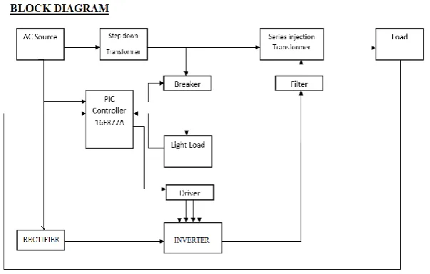
step down transformer, Microcontroller, single phase inverter, series injection transformer and sensitive load. Supply voltage from distribution transformer i.e 230v is stepped down to desired voltage with the help of tap changing transformer is fed into rectifier and then converted into DC. The obtained DC voltage is maintained constant with the help of the voltage regulator applied to the microcontroller where the reference voltage and magnitude traction is programed ,where the input voltage magnitude is compared with this reference voltage magnitude, when equal supply is directly connected to the load. In case voltage magnitude less than required voltage it will boost the required amount of voltage injected by means of phase to neutral injection in series injection transformer then it is connected to the sensitive load. If voltage magnitude is greater than required voltage, it reduce to the desired voltage and fed to the sensitive load with the help of neutral to phase current injection in series injection transformer.
IV. SYSTEM CONFIGURATION
The basic idea of a DVR is to inject the missing voltage cycles into the system through series injection transformer whenever voltage sags are present in the system supply voltage. As a consequence, sag is unseen by the loads. During normal operation, the capacitor receives energy from the main supply source. When voltage dip or sags are detected, the capacitor delivers dc supply to the inverter. The inverter ensures that only the missing voltage is injected to the transformer. A relatively small capacitor is present on dc side of the PWM solid state inverter, and the voltage over this capacitor is kept constant by exchanging energy with the energy storage reservoir. The required output voltage is obtained by using pulse-width modulation switching pattern.
V. SIMULATION
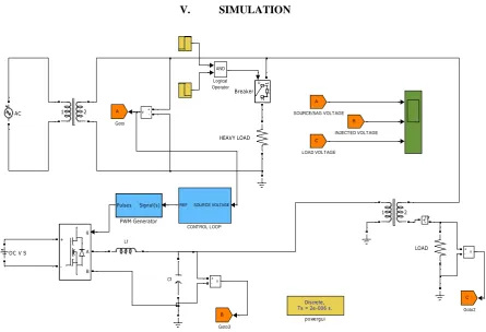
Figure 2 Simulation for DVR
Lf
Cf
Discrete, Ts = 2e-006 s.
powergui v + -v+ -v + -g A B + -A SOURCE/SAG VOLTAGE Signal(s) Pulses PWM Generator AND Logical Operator 1 2 1 2 C LOAD VOLTAGE LOAD B INJECTED VOLTAGE HEAVY LOAD B Goto3 C Goto2 A Goto
DC V S
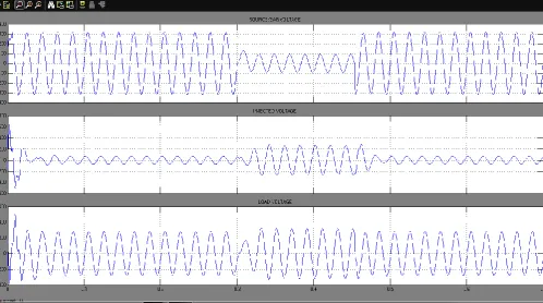
Figure 3 Simulation output for voltage sag recovery by using DVR
In above diagram Fig 2,3 are the circuit diagram, simulation output of a DVR respectively The simulation is simulated by using MATLAB A whole simulation will be kept under a discrete mode because to occur an instant output in a discrete manner. An input voltage of 230 rms is fed to the sensitive load when there is no interruption and sag occurs at 0.3ms to 0.45ms where the peak voltage is reduced till Vp = 200V. this is eliminated by generating waveform using pulse width modulation(PWM) generator and adding it with sag waveform with the help of Series injection Transformer so that it will compensates the losses occurs during voltage sag through which sensitive equipment are saved
Vp= Peak-Peak Voltage
Vpinj=Injected voltage VL=Load Voltage
VL=Vp + Vpinj (1)
While sag occurs at t=0.30 ms to t=0.45ms
Vp=400 V (2)
Vpinj=400V (3)
Substitute (2), (3) in (1)
Table 1
SUBSYSTEM-CONTROL LOOP
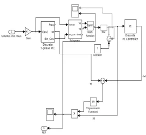
Figure 4 Circuit diagram for controller loop
wt
del
|v| fc/2
1 REF
sin
Trigonometric Function1
Vsmax
sin_cos Vd
Vq
sinwt
Subsystem hypot
Math Function
-K-Gain
PI
Discrete PI Controller
V(pu) Freq
wt
Sin_Cos
Discrete
1-phase PLL 1
Constant 1
SOURCE VOLTAGE
SIMULATION PARAMETERS
Input voltage 230*1.414V
DC Source 12 V
Load resistance 10 ohm
Frequency 50Hz
Isolation transfer 1:1 (250 Watt)
Series injection
transformer 1:1 (250 Watt)
Inductive filter 38mH
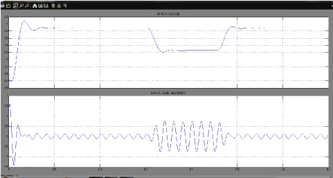
Figure 5 Simulation output for controller unit
From fig 4,5 shows the simulation output of control unit ,Control unit control the load voltage by magnitude traction or magnitude extraction method, where the real voltage is obtained from multiplication of source voltage and sinusoidal angle similarly imaginary voltage is obtained from multiplication of inversed source voltage and cosine angle from which Vd and Vq are calculated which fed to hypot where the voltage is compared with reference voltage and produce a nominal waveform in case sag occurs it will show the difference as shown in figure 5. Pulse Width Modulation (PWM) generator will generate sinusoidal pulse only when the difference in nominal waveform occurs which is injected to the source voltage with the help of series injection transformer to obtain constant load voltage to the sensitive load
For Magnitude traction
Vsource * Sinwt = Vreal (5)
-Vsource *coswt = Vimg (6)
Vd=Vreal*sinwt-Vimg*coswt (7)
Vq=Vreal*coswt+Vimg*sinwt (8)
VI. CONCLUSION
A design and development of Dynamic Voltage Restorer (DVR) for voltage Sag and Swell
compensation for improving power quality is stimulated by using MATLAB. When compared with the existing
method Where Fast Mitigation of voltage sag is achieved by mathematical modeling simulation done in
1. Sandy K, Jaya Laxmi A, Soni MP. Design of PI and fuzzy controller for dynamic voltage restorer (DVR). AASRI Procedia 2 2012;2:149–55.
2. Boonchiam P, Mithulananthan N. Understanding of dynamic voltage restorers through MATLAB
simulation. Thammasat Int J Sic Tech 2006;11(3):1–6.
3. El-Tayyan AA. PV system behavior based on datasheet. J Electron Dev 2011;9:335–41.
4. Elgendy MA, Zahawi B, Atkinson DJ. Assessment of perturb and observe MPPT algorithm
implementation techniques for PV pumping applications. IEEE Trans Sustain Energy 2012;3(1):21– 33.
5. Hsieh YP, Chen JF, Liang TJ, Yang LS. Novel high set-up DC–DC converter for distributed generation system. IEEE Trans Ind Electron 2011;99. 1.
6. Nielsen JG, Newman M, Nielsan H, Blaabjerg F. Control and testing of a dynamic voltage restorer (DVR) at medium voltage level. IEEE Trans Power Electron 2004;19(3):806–13.
7. R. Muralekrishnen ; P. Sivakumar “Improving the power quality performance for distributed power generation” 21-22 March 2012
8. Amit Meena, Shirazul Islam, Sandeep Anand Department of Electrical Engineering,Indian Institute of
Technology Kanpur “Design and Control of Single Phase Dynamic” July. 2013
9. Tavighi Dept. of Electr. & Comput. Eng., Univ. of British Columbia, Vancouver,BC, Canada H. Abdollahzadeh ; J. Marti “Fast response DVR control strategy design to compensate unbalanced voltage sags and swells in distribution systems” 21-25 July 2013
10. Mahmoud Zadehbagheri¹, Rahim Ildarabadi*² and Majid Baghaei nejad³ Faculty of Electrical,
Department of Electrical Engineering, Hakim Sabzevari University, “Modeling and Simulation of Dynamic Voltage Restorer for Voltage Sag/Swell Compensation in Power Distribution Networks” Jul. 06, 2015