972 | P a g e
ERGODIC CHANNEL CAPACITY OF
MULTIPLE INPUT MULTIPLE OUTPUT SYSTEM
Sarala Patchala
1, Dr. M. Sailaja
21
Ph.D, Research scholar, Department of ECE, JNTUK, KAKINADA(India)
2
Professor, Department of ECE, JNTUK, KAKINADA(India)
ABSTRACT
To design & implement the Ergodic channel with Gaussian for the different number of transmitter and receiver.
Irrespective of that the channel capacity is identify without knowing its channel state information for increased
number of Transmitter & Receivers. The better SNR provides with better faster data transmission. Channel
capacity improves with increased transmitter & Receiver.
Keywords: Ergodic, MIMO, channel capacity
I. INTRODUCTION
The random variable said to be Ergodic if, the mean of the random variable should be constant. The channel
matrix has singular value decomposition . Where and are
unitary matrices. The Channel Capacity (CC) of a multiple antennas with increased by factor of
without using additional transmits power.
II. SYSTEM MODEL
In the deterministic MIMO channel system with [2] & receive antennas represented by x the channel
matrix now consider the transmitter symbol vector , which is calm of independent
input symbols .
Where is a noise vector which is assumed to be a symmetric Gaussian
with zero mean & unit variance (0, 1) [4].
The noise vector is a circular symmetric with the same distribution as z for any θ. The
auto-correlation of transmitted vector is
973 | P a g e
III. PROPOSED MIMO CHANNEL
The CC of a deterministic channel is defined as
Where is the probability density function of the transmitted vector x [3]. The mutual information of the
two continuous random vectors x and y is given by (1)
Then,
(2)
3.1.
Design considerations
The auto correlation matrix of the y random variable is
(3)
=
The total transmitted power limited to
(4)
3.1. Channel capacity when CSI is at Transmitter
Now CSI is available at the transmitter side [1] signal decomposition, in which a transmitted signal [7] is pre
processed with the P in the transmitter and then a received signal is post processed with in the receiver.
Where
Then the mutual information of Y and Z is
(6)
(7)
974 | P a g e
Then,(9)
Now the CC [2] of deterministic MIMO channel is expressed as
(10)
The output signal receiver can be,
(11)
(12)
Where, , U is a unitary matrix
3.2. Channel capacity when CSI is not at Transmitter
H is not known then, the transmitted vector is ,
CC is
(13)
Assume , if r=N then
CC for N parallel Channel
(14)
3.3. Channel capacity for MIMO channel
MIMO deterministic randomly channel matrix. In practice channel assume Ergodic channel [9].
In MIMO channel changes randomly. H is a random matrix, which means that its CC [11] changes
randomly. MIMO CC can be given by its time average. The random channel is an Ergodic process.
(15)
3.4. MIMO channel capacity
The MIMO CC is specified by a sum of the capacities of the virtual single input single output channel [12], i.e.
(16)
=
For i=1 ….r-1, r.
975 | P a g e
Where is a constant and is defined as(17)
It was solved by water pouring algorithm. The more is power allocation for the mode with higher SNR [5].
3.4. Channel capacity for open loop system
Ergodic CC for the open loop system is
(18)
3.5. Channel capacity for open loop system
Ergodic CC for the closed loop system is
=E
Where (19)
IV. SIMULATION RESULTS
The Ergodic CC [6] when CSI is not available at the transmitter side. Initial assumptions are number of iteration
10000, SNR initially at 0db to upto52db,
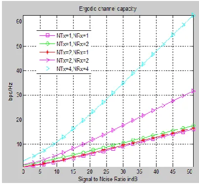
In Fig2 illustrates that the Ergodic CC with respect to Signal to Noise Ratio (SNR) with five different possible
cases. Where observed that these are 1Tx&1Rx. 1Tx. &2Rx, 2Tx&1Rx, 2Tx&2Rx, 4Tx &4Rx. The SNR
range is from 0 to up to 52db. Where the SNR at the 26db is 30bps/Hz. Rest of the case it is observed that less
capacity 30bps/Hz.
976 | P a g e
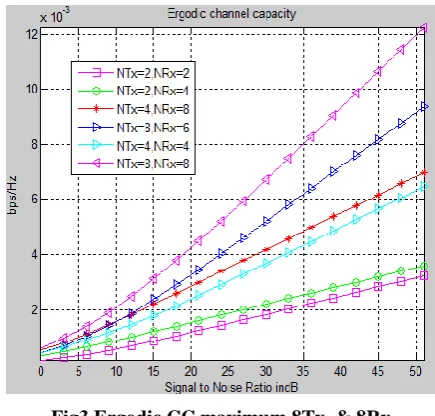
In Fig3.shows six possible cases simulation response of Ergodic CC. These are 2Tx&2Rx. 2Tx. &4Rx,4Tx&8Rx, 8Tx. &6Rx, 4Tx&4Rx and 8Tx&8Rx. antennas. It observed that SNR [8] is at 15db 4x8 antennas
with capacity 2.1x10⁻³bps/Hz and 8x8 antenna 3.41x10⁻³ bps/Hz.
Fig3.Ergodic CC maximum 8Tx. & 8Rx
In Fig4.shows six possible cases simulation response of Ergodic CC. These are 1Tx&1Rx. 1Tx. &2Rx,
2Tx&1Rx, 2Tx&2Rx, 4Tx &4Rx. and 8Tx&8Rx. antennas with 3x10⁻³bps/Hz and 8Tx. & 8Rx. capacity 5.9x10
-3 bps/Hz.
Fig 4.Ergodic CC of maximum 8Tx. & 8Rx
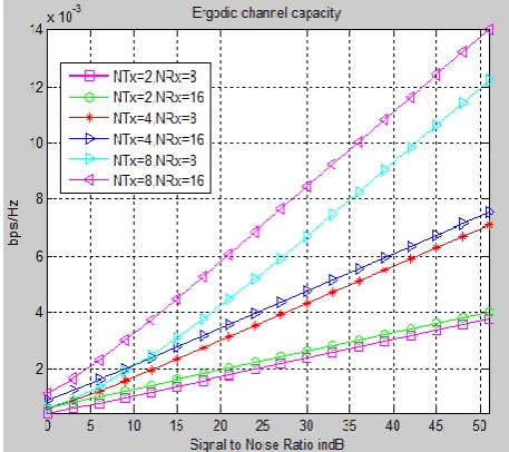
In Fig5.shows six possible cases simulation response of Ergodic CC. These are 2Tx& 8Rx. 2Tx. &16Rx.
4Tx&8Rx, 4Tx. &16Rx, 8Tx &8Rx. and 8Tx&16Rx. antennas. It observed that SNR is at 30db 4x16 antennas
977 | P a g e
Fig 5 CC maximum 8Tx& 16RxFig 6.Ergodic CC maximum 16Tx & 128Rx
In Fig6.shows six possible cases simulation response of Ergodic CC. These are 8Tx& 8Rx, 8Tx&16Rx,
8Tx&32Rx, 8Tx.&64Rx,16Tx.&64Rx. and 16Tx&128Rx. antennas. It observed that SNR is at 20db 8x16
978 | P a g e
Fig7.channel known vs channel unknownIn illustrates Fig 7.Ergodic CC for correlated channel for case (i) 4x4 channel and case (ii) 5x5 channel for both
unknown and known. Where SNR is at 20dB 5x5 unknown channel is at a capacity of 25bps/Hz and for known
channel with 28bps/Hz.
V. CONCLUSION
The number of transmitting & receiving antennas is increased without any increased power levels. The
antenna’s are improved their channel capacity with respect to the channel matrix.
REFERENCES
[1]P.Viswanath,D.N.C.Tse,& R. Laroia, “Opportunistic beam forming using dump antennas,” IEEE Trans. Inf.
Theory, vol. 48, no. 6, pp. 1277–1294,2002.
[2]B.Hochwald,T.Marzetta,&V.Tarokh,“Multi-antenna channel-hardening and its implications for rate feedback
and scheduling,” IEEE Trans. Inf. theory, vol. 50, no. 9, pp. 1893–1909,2004.
[3]G.Durisi,A.Tarable,C.Camarda,&G.Montorsi,“On the capacity of MIMO Wiener phase-noise channels,” in
Proc. Inf. Theory Appl,Feb. 2013, pp. 1–7
[4]N.N.Moghadam,P.Zetterberg,P.Händel,&H. Hjalmarsson, “Correlation of distortion noise between the
branches of MIMO transmit antennas,” in Proc. IEEE, Sep. 2012, pp. 2079–2084.
[5]DW.K.Ng, E.S.Lo,&R.Schober,“Energy-efficient resource allocation in OFDMA systems with large numbers
of base station antennas,” IEEE Trans. Wireless Commun., vol. 11, no. 9, pp. 3292–3304, Sep. 2012.
[6] H.Q.Ngo,E.G.Larsson,&T.L. Marzetta,“Energy and spectral effi- ciency of very large multiuser MIMO
979 | P a g e
[7] W. Zhang, “A general framework for transmission with transceiver distortion and some applications,” IEEETrans. Commun.,vol. 60, no. 2, pp. 384–399, Feb. 2012
[8] X. Gao,O.Edfors,F.Rusek, &F. Tufvesson, “Linear pre-coding performance in measured very-large MIMO
channels,” in Proc. IEEE VTC Fall, Sep. 2011, pp. 1–5.
[9]C.Studer&E.G.Larsson,“PAR-aware large-scale multi-user MIMOOFDM downlink,” IEEE J. Sel. Areas
Commun., vol. 31, no. 2, pp. 303–313, Feb. 2013.
[10] E. Björnson, M. Kountouris, M. Bengtsson, and B. Ottersten, “Receive combining vs. multi-stream
multiplexing in downlink systems with multi-antenna users,” IEEE Trans. Signal Process. vol. 61, no. 13,
pp. 3431–3446, Jul. 2013.
[11] N. O’Donoughue and J. M. F. Moura, “On the product of independent complex Gaussians,” IEEE Trans.
Signal Process., vol. 60, no. 3, pp. 1050–1063, Mar. 2012.
[12] H. Yin, D. Gesbert, M. Filippou, and Y. Liu, “A coordinated approach to channel estimation in large-scale
multiple-antenna systems,” IEEE J.Sel. Areas Commun.,vol. 31, no. 2, pp. 264–273, Feb. 2013.
[13] A. M. Tulino and S. Verdú, “Random matrix theory and wireless communications,” Found. Trends
Commun. Inf. Theory, vol. 1, no. 1, pp. 1–182, 2004.
Author’s:
.
. Dr.M.Sailaja, Professor in JNTUK KAKINADA, ECE Department. Guiding several no.of UG &PG project and few more Phd projects with 20+ teaching and industry experience.