73
DEVELOPMENT OF ASSORTED SOLID
OBJECT BASED ON B-SPLINE
Milan Motta
1, Shadab Imam
21 2
Mechanical Engineering
1 Columbia Institute of Engineering & Technology, Raipur 2 Christian College of Engineering & Technology, Bhilai
1[email protected],09893292979(Mob.)
ABSTARCT:
Functionality of an object is best when it possesses desired properties at required locations. In many cases, Homogeneous objects fail to deliver what they are intended to. So, new materials called “heterogeneous materials”, which have gradual variation of material and material properties have come into play to replace homogeneous materials in the prevailing conditions, where the later fails. In this paper need for heterogeneous objects have been explained with examples. Manufacturing processes for heterogeneous objects are given in brief. The present work deals with the modeling of heterogeneous objects. Benefits of using B-splines for volume modeling are utilized in the present work by extending the scheme for heterogeneous objects. A B-spline representation of volumes is developed to represent not only the surface boundary but also the interior of a 3D object with varying material composition within the volume. Based on this scheme a small part of a femur is modeled.
Keywords: Assorted Solid; B-spline; Knot Vector.
1. INTRODUCTION
Objects in geometric modeling systems tend to be generated by primitive solids based on simple geometric primitives, half space models, and/or boundary models. These primitives can be manipulated by a set of modeling tools, combined by using Boolean operations, and rendered using a variety of visible surface algorithms.
The more general models have been the boundary models, frequently using a parametric patch formulation to describe the face boundaries of a solid. These patch models have been in use for some time in visible-surface algorithm development, and various modeling methods have been proposed to deal with these objects. However, when dealing with heterogeneous objects with material variation in three dimensional space, it is natural to deal objects as solid, rather than describing a volume of space by specifying surrounding surfaces. For this purpose parametric B-spline based volume modeling is used. B-spline solid is a simple tensor-product extension of both the B-spline curve and the B-spline patch.
.
2. B-SPLINE CURVES
E-ISSN: 2321–9637
Volume 1, Issue 4, November 2013
International Journal of Research in Advent Technology
Available Online at:
http://www.ijrat.org
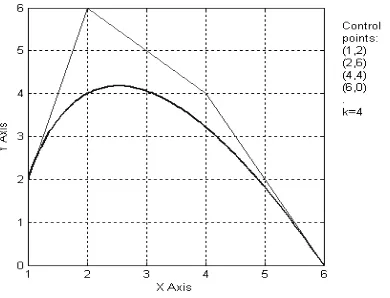
[image:2.595.204.399.188.337.2]74 Figure I A cubic B-spline curve with four control points:
approximation scheme to establish the relationship between the curve and the polygon. This scheme is provided by the choice of basis function. The basis function used by the B-Spline curves is called B-Spline basis.
2.1. Properties of B-splines
(1) The behavior of the B-spline curve is no global; it means changing position of any one vertex does not affect the entire curve. It is due to the fact that each vertex is associated with a unique basis function. Thus, each vertex affects the shape of a curve only over a range of parameter values where its associated basis function is nonzero.
(2) The sum of the B-spline basis functions for any parameter value is one.
1 , 1
( )
1
n
i k i
N
t
+
=
≡
∑
(3) Except for k=1 each basis function has precisely one maximum value.
(4)The maximum order of the curve is equal to the number of defining polygon vertices.
(5)The curve exhibits the variation diminishing property. Thus curve does not oscillate about any straight line more often than its defining polygon.
(6)The curve generally follows the shape of the defining polygon.
(7)Any affine transformation can be applied to the curve by applying it to the defining polygon vertices; i.e., the curve is transformed by transforming the defining polygon vertices.
(8)The curve lies within the convex hull of its defining polygon.
3. KNOT VECTOR
It is a monotonically increasing series of real numbers i.e. ai ≤ ai+1. The choice of knot vector has a significant
influence on the B-spline basis functions Ni,k(t) and hence on the resulting B-spline curve.
3.1.Types of Knot Vector
Sections Uniform, open uniform (or open), and non uniform.
75 3
0
In a uniform knot vector, individual knot values are evenly spaced. This type of knot vector is generally used for closed B-spline curves. e.g. [0 1 2 3 …………13] is used to draw a closed curve. An open uniform knot vector has multiplicity of knot values at the ends equal to the order k of the B-spline basis function. These are used for open curves. Non uniform knot vectors may have either unequally spaced and/or multiple internal knot values. They may be periodic or open. These are better suited for generating analytical shapes like circle, parabola etc.
3.2.B-Splines Surface
By taking Cartesian or tensor product, B-spline curve can be extended to B-spline surfaces. It is defined by.
1 1
, , ,
1 1
( , )
( )
( )
n m
i j i k j l
i j
P u v
B N
u M
v
+ +
= =
=
∑∑
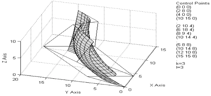
Where Ni,k(u) and Mj,l(v) are the B-spline basis functions in the biparametric u and v directions, respectively. The
same definition of the basis functions given previously is applied here. Again Bi,j’s are the vertices of a defining
[image:3.595.168.466.172.317.2]polygon net. n+1 and m+1 are the number of defining polygon vertices in the u and v directions, respectively.
Figure III: A B-spline surface with net of control points
[image:3.595.126.465.545.700.2]E-ISSN: 2321–9637
Volume 1, Issue 4, November 2013
International Journal of Research in Advent Technology
Available Online at:
http://www.ijrat.org
76
3.3.B-Spline Hyperpatch
The three dimensional B-spline hyperpatch is a simple tensor –product extension of both the B-spline curve and B-spline patch. The trivariate B-spline hyperpatch is given by
1 1 1
, , , , ,
1 1 1
( , , )
( )
( )
( )
l m n
i j k i r j s k t
i j k
P u v w
B
L
u M
v N
w
+ + +
= = =
=
∑∑ ∑
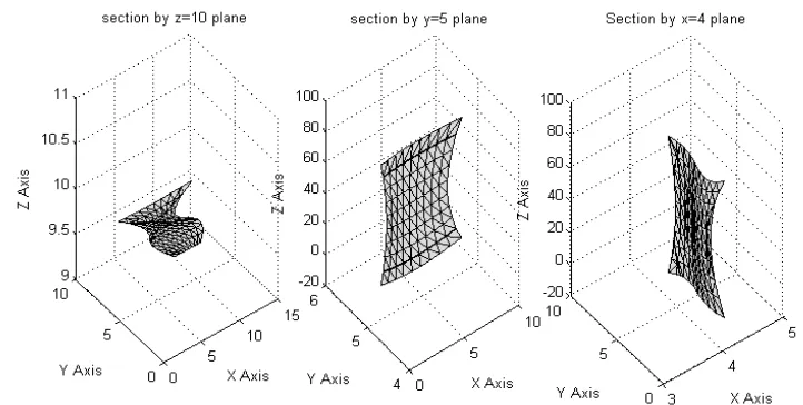
Where l+1, m+1, n+1 are number of points in u,v,and w directions respectively. Li,r, Mj,s,Nk,t are the B-spline blending functions as defined earlier. Figure 2.5 and 2.6 represent a solid object and its sections by planes parallel to z,y, and x planes. In figure 2.7 a bone like object is created by B-spline modeling.
4. SOFTWARE DEVELOPMENT
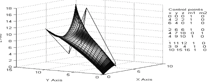
[image:4.595.97.458.182.364.2]To represent heterogeneous objects, a software is developed using MATLAB and C-language. C programming is used for calculation of B-spline basis functions, which are computationally expensive and MATLAB is used for rendering and other computations. Input required for the software are x,y,z coordinates and normalized quantity of any one material at control points. Apart from this, user can select value of k in any or all the parametric direction to control the order of curve. More the value of k smoother the variation will be. Figure V shows a heterogeneous surface created using this software. With the given input, points inside and at boundary of the object are calculated by using equations [3.2] and [3.3]. These points are stored in three-dimensional matrices each for x,y,z,m’ and m’’. User can increase or decrease the number of points to represent the solid, more number of points will ensure more accuracy but with the expense of more computational time. Only outside boundary of the solid will be shown for rendering purpose. This software also allows the user to view any section of the object, parallel to x,y, and z-planes. Using this method heterogeneous primitives such as heterogeneous cuboids, heterogeneous cylinders with different types of material variation are created.
77 Figure V: A B-spline surface with material variation
5. RESULTS
Cubes constructed by twenty seven points (three planes, nine points in each plane) and their sections by planes parallel to x, y, and z planes. In figure VI center point of all the three horizontal planes contain m1=1(m2=0) and
outer eight points of each plane contain m1=0(m2=1), value of k is taken as three. All the outer points have same
composition, so there should not be any material variation but at the center material composition is different therefore composition should vary smoothly from outer surface to center. Similarly in figure VII, m1=1(m2=0) is
only at center point of the central horizontal plane and at all other points m1=0(m2=1), therefore all the six outer
faces should have same material composition but material should vary as one approaches towards the center of the cube. As expected, material variation is obtained by B-spline modeling.
E-ISSN: 2321–9637
Volume 1, Issue 4, November 2013
International Journal of Research in Advent Technology
Available Online at:
http://www.ijrat.org
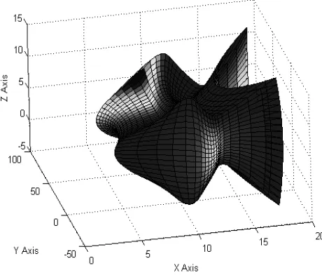
78 A sculptured object is created by B-spline modeling (figure VIII). B-spline modeling not only allows user to create sculptured objects but modification of these objects is also simple. Once created, user can modify the object as per the need by rearranging the control points of the object. Another use of B-spline modeling is in reverse engineering where object is already in existence and its model is created by measuring coordinate points of the object.
[image:6.595.176.406.251.447.2]Figure VIII: A Sculptured Object
79
6. CONCLUSION
A modeling scheme for heterogeneous objects based on B-splines is developed. This scheme inherits the advantage of B-splines to represent the sculptured free-form objects. The present work introduces method of creating and visualizing free-form heterogeneous model by use of B-spline material hyperpatch. Prototype software has been developed for creating and visualizing heterogeneous model. This software is also used to model a real world heterogeneous object with available point cloud data. This way space required to store the object models can be reduced by storing only few points rather than all the points defining the object. These stored points can be used to regenerate the model for applications such as analysis and rapid prototyping. Those Points having discontinuity in geometry or material composition must be selected to model the object, so that model should represent the actual object more precisely.
Acknowledgments
The authors take opportunity to thank Management of Christian College of Engineering & Technology, Bhilai (C.G.) for their valuable guidance, support and continuous encouragement by providing facilities.
References
[1] Siu Y.K., et al. “Modeling the material grading and structures of heterogeneous objects for layered manufacturing” Computer-Aided Design 34 (2002) 705-716Albert, R.; Jeong, H.; Barab´asi, A.-L. (1999): Diameter of the world-wide Web. Nature, 401, pp. 130–131. [2] Kumar V., et al. “A framework for object modeling” Computer-Aided Design 31 (1999) 541-556Bharat, K.; Broder, A. (1998): A
technique for measuring the relative size and overlap of public Web search engines. Computer Networks, 30(1–7), pp. 107–117. [3] Liu H., Patrikalakis et al. “A Design and Post-processing System for Local Composition Control in Solid freeform Fabrication”
Massachusetts Institute of Technology SIGKDD explorations, 1(2), pp. 1–11.
[4] Pompe W., et al. “ Functionally graded materials for biomedical applications” Materials Science and Engineering A362 (2003) p.40-60
[5] Kieback B., et al., “Processing Techniques for Functionally Graded Materials” Materials Science and Engineering A 362(2003) 81-105.
[6] Mattern A., et al.., “Multi-phase Ceramics by Computer-Controlled Pressure Filtration”, Journal of the Europian Ceramic Society 24 (2004) 3219-3225.
[7] Bondi S.N., et al., “Multimaterial and Advanced Geometry Deposition via Laser Chemical Vapour Deposition”, Rapid Prototyping Journal, Volume 9, number 1(2003) 81-105.
[8] Arpan Biswas, et al. “ Heterogeneous material modeling with distance fields” Computer Aided Geometric Design 21 (2004) 215-242 [9] Kenneth I.Joy ,“Utilizing Parametric Hyperpatch Methods for Modeling and Display of Free-Form Solids”,ACM Symposium on
Solid and Physical Modeling(1991)p.245-254
[10] David F. Rogers, et al. “Mathematical Elements for Computer Graphics”. Tata McGraw-Hill, 2002.
Milan Motta is an academic in a leading institute of middle India in the region of Raipur Chhattisgarh. He has done in bachelor’s degree in Mechanical engineering from Pt. R.S.U, Raipur (C.G.), Masters Degree in CAD/CAM Robotics from SVTU, Bhilai and Masters of Business administration with specialization in Operations Management from IGNOU and pursuing his Doctorate program with specialization in Micro and Macro Structural Analysis of materials from University of Petroleum and Energy Studies, Dehradun He has participated in many national and international conferences and contributed various research papers published in proceedings and, some of which have been published in the renowned Journals.