Available online at www.ijrat.org
83
Steady State Comparative Performance Analysis Of
ILBC-UPQC System With PI And PR Controllers
G.V. Prasanna Anjaneyulu
1, Dr.P. Sangameswara Raju
21Associate Professor, 2Professor (Retd)
Electrical & Electronics Engineering, Tirumala Engineering College Narasaraopet, Andhra Pradesh, India Electrical & Electronics Engineering, S.V.University College of Engineering, Tirupathi Andhra Pradesh, India
[email protected], [email protected]
Abstract:Unified Power Quality Conditioner (UPQC) is an useful FACTS controller in power system network for improvement of voltage quality. The objective of this work is to improve the steady state response of ILBC-UPQC using suitable controller. This work gives selection of suitable controller for improved steady state performance of ILBC-UPQC system. The steady state responses with Proportional Integral PI and Proportional Resonant PR controllers are presented in this paper. The MATLAB results of Proportional Integral PI based ILBC-UPQC system are compared with those of Proportional Resonant PR controlled ILBC-UPQC system. The comparison is done in terms of steady state error. MATLAB results shows that improved steady state performance with Proportional Resonant PR controller of ILBC-UPQC system.
Keywords—Unified Power Quality Conditioner (UPQC); PI Controller; PR Controller;
1. INTRODUCTION disconnection of large industrial loads and reactive power compensating capacitors; and 3) voltage and/or current harmonic distortion due to the UPQC unified power quality conditioner has superior performance and the capacity to reduce almost all major PQ problems. UPQC is the most attractive system for PQ improvement in spite of its high cost, complex structure, and control [1]-[3]. The basic structure of a UPQC is shown in Figure.1.
Figure 1: Basic Structure of UPQC
Generally, the voltage sags and swells are short duration PQ problems. Thus, in UPQC-P and UPQC_Q, series inverter VA loading will only be utilized for short durations. On the other hand, the shunt inverter VA rating is fully utilized thorough out the operation, due to continuous load reactive power support and current harmonic compensation. To enhance the utilization of series part of UPQC during steady state, part of load reactive power is
Available online at www.ijrat.org
84 reduction in the percentage of swell compensation
capability.
2. PROPOSED SYSTEM CONFIGURATION
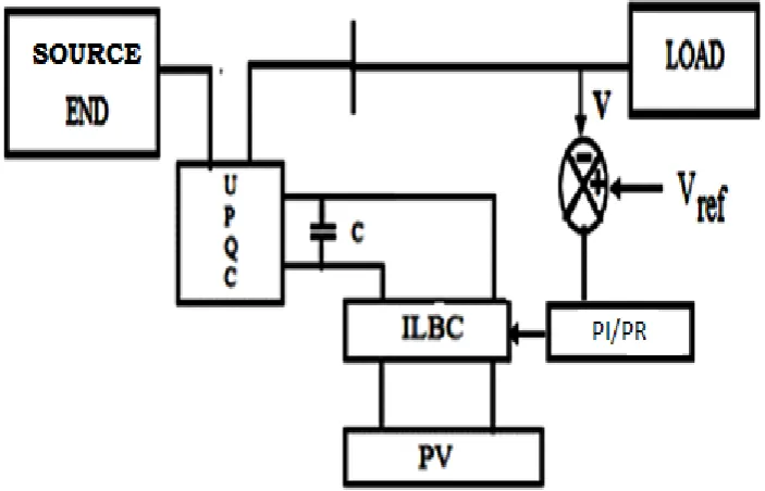
The block diagram of proposed closed loop PI/PR fed Inter Leaved Boost Converter
(ILBC) fed UPQC system is shown in Figure 2. The capacitor of UPQC is charged by the output of Inter Leaved Boost Converter (ILBC). The output voltage of PV is boosted using Inter Leaved Boost Converter (ILBC). For ILBC the modified pulse width signals are fed from feedback obtained via closed loop controllers. Here feedback is collected from load voltage.
Figure 2: Block Diagram of proposed closed loop PI/PR fed ILBC-UPQC system
A. Mathematical Analysis for Proportional Integral Controller
As the name suggests it is a combination of proportional and an integral controller. The output (also called the actuating signal) is equal to the summation of proportional and integral of the error signal. Now let us analyze proportional and integral controller mathematically. As know in a proportional and integral controller output is directly proportional to the summation of proportional of error and integration of the error signal, writing this same mathematically
𝐴(𝑡) ∞ ∫ 𝑡
𝑑𝑡 + (𝑡) (2.1)
Removing the sign of proportionality,
𝐴(𝑡)=𝐾i∫ 𝑡
𝑑𝑡+𝐾𝑃 (𝑡)
(2.2)
Here, Ki and Kp Proportional constant and Integral
constants respectively.
B. Mathematical Analysis for Proportional Resonanant Controller
As the name suggests it is a combination of Proportional and Resonant controller. The output of PR controller is as follows
VO(S) = E(S)
[K1+ ] (2.3)
Here K1, K2 are Proportional and Resonant
constants of PR controller.
3. IMPLEMENTATION OF PROPOSED SYSTEM
Available online at www.ijrat.org
85
Table 1: Parameters for PI and PR colosed loop systems
PARAMETERS VALUE
R1, R2, R3 0.1Ω, 0.5Ω,0.8Ω
L1, L2,L3 3mH, 30mH, 40mH
Cin 50µF
Cb 9000µF
Ro, Lo 200Ω, 100mH
A. Implementation of Proportional Integral (PI) Controller
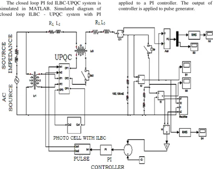
The closed loop PI fed ILBC-UPQC system is simulated in MATLAB. Simulated diagram of closed loop ILBC - UPQC system with PI
controller is shown in Figure 3.1. Load voltage is rectified and converted in to an analog signal. It is compared with the reference voltage. The error is applied to a PI controller. The output of PI controller is applied to pulse generator.
Figure 3.1: Simulation Diagram of proposed closed loop PI fed ILBC-UPQC system
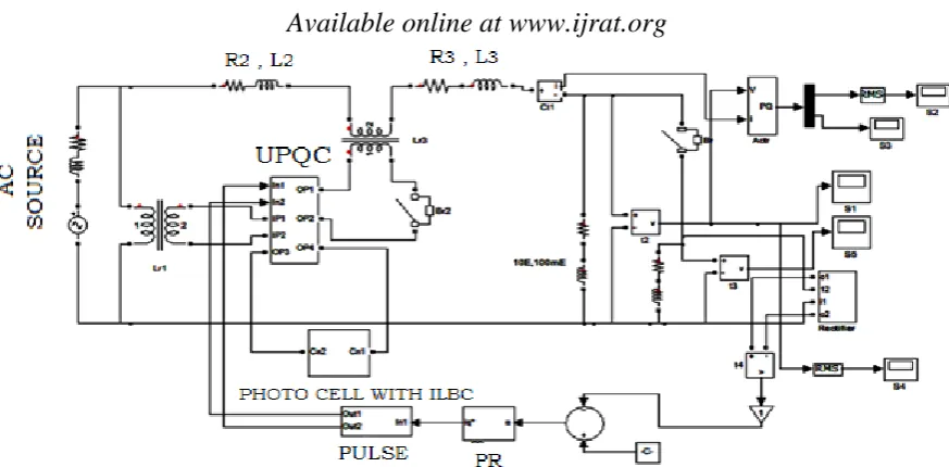
B. Implementation of Proportional Resonant (PR) Controller
The closed loop PR fed ILBC-UPQC system is simulated in MATLAB. Simulated diagram of closed loop ILBC - UPQC system with PR controller is shown in Figure 3.2. Load voltage
Available online at www.ijrat.org
86
Figure 3.2: Simulation Diagram of proposed closed loop PR fed ILBC-UPQC system
4. SIMULATION RESULTS
The closed loop PI fed ILBC-UPQC system is simulated in MATLAB/SIMULINK..
RMS value of receiving end voltage is shown in figure 4.1. The steady state error is 5.3 V in PI controller.
Figure 4.1: Receiving end voltage RMS value
The closed loop PR fed ILBC-UPQC system is simulated in MATLAB/SIMULINK. RMS value of
receiving end voltage is shown in figure 4.2. The steady state error is 1.8 V in PR controller.
Figure 4.2: Receiving end voltage RMS value
Available online at www.ijrat.org
87
Table 1: Comparison of Steady State Error for PI and PR controllers fed ILBC-UPQC system
Controller Steady State Error
PI 5.3
PR 1.8
5. SIMULATION RESULTS
Proportional Integral PI and Proportional Resonant PR controller based ILBC-UPQC systems are modeled and simulated using MATLAB/SIMULINK and steady state performance i.e. steady state error is analyzed. The results indicated that the steady state error with Proportional Resonant controller is very less than that of Proportional Integral PI Controlled ILBC-UPQC system. The steady state error is reduced by 3.5 Volts by replacing Proportional Integral PI controller with Proportional Resonant PR Controller. The contributions of the present work are as follows: Proportional Resonant PR controller is proposed to decrease the Steady state error.The disadvantage is that the hardware of ILBC becomes twice that of SBC.
REFERENCES
[1] B. Singh, K. Al-Haddad, and A. Chandra, ―A review of active power filters for power quality improvement,‖ IEEE Trans. Ind. Electron., vol. 45, no. 5, pp. 960–971, Oct. 1999.
[2] V. Khadkikar, ―Enhancing electrical power quality using UPQC: Acomprehensive overview,‖ IEEE Trans. Power Electron., vol. 27, no. 5, pp. 2284–2297, May 2012.
[3] W. C. Lee, D.M. Lee, and T. K. Lee, ―New control scheme for a unified power-quality compensator-Q with minimum active power injection,‖ IEEE Trans. Power Del., vol. 25, no. 2, pp. 1068–1076, Apr. 2010.
[4] M. Yun, W. Lee, I. Suh, and D. Hyun, ―A new control scheme of unified power quality compensator-Q with minimum power injection,‖ in Proc. IEEE 30th Annu. Ind. Electron. Soc. Conf., Nov. 2–6, 2004, pp. 51– 56.
[5] V. Khadkikar and A. Chandra, ―UPQC-S: a novel concept of simultaneous voltage sag/swell and load reactive power compensations utilizing series inverter of UPQC,‖ IEEE Trans. Power Electron., vol. 26, no. 9, pp. 2414–2425, Sep. 2011.
[6] V. Khadkikar and A. Chandra, ―A new control philosophy for a unified power quality conditioner (UPQC) to coordinate load-reactive power demand between shunt and
series inverters,‖ IEEE Trans. Power Del., vol. 23, no. 4, pp. 2522–2534, Oct. 2008.
[7] D. Kisck, V. Navrapescu, and M. Kisck, ―Single-phase unified power quality conditioner with optimum voltage angle injection for minimum VA requirement,‖ in Proc. IEEE Int. Symp. Ind. Electron., Jun. 17–21, 2007, pp. 2443–2448.
[8] H. Ryoo, G. Rim, T. Kim, and D. Kisck, ―Digital-controlled singlephaseunified power quality conditioner for non-linear and voltage sensitive load,‖ in Proc. IEEE 30th Annu. Ind. Electron. Soc. Conf. , Nov. 2–6, 2004, pp. 24– 29.
[9] Y. Y. Kolhatkar, R. R. Errabelli, and S. Das, ―A slidingmode controller based optimum UPQC with minimum VA loading,‖ in Proc. PowerEng. Soc. Gen. Meeting, Jun. 12–16, 2005, pp. 871–875.
[10] Y. Y. Kolhatkar and S. Das, ―Experimental investigation of a singlephaseUPQC with minimum VA loading,‖ IEEE Trans. Power Del., vol. 22, no. 1, pp. 371–380, Jan. 2007. [11] G. S. Kumar, P. H. Vardhana, B. K. Kumar,
and M. K. Mishra, ―Minimization of VA loading of unified power quality conditioner (UPQC),‖ in Proc. Power Eng., Energy Elect..Drives, Mar. 18–20, 2009, pp. 552–557. [12] G. S. Kumar, B. K. Kumar, andM.M. Kumar,
―Optimal VA loading of UPQC during mitigation of unbalanced voltage sags with phase jumps in three-phase four-wire distribution system,‖ in Proc. Int. Conf. PowerSyst. Technol., Oct. 24–28, 2010, pp. 1– 8.
[13] Podlubny, I.: Fractional - order systems and PI_D_ controllers, IEEE Trans. On Automatic Control, vol.44, no.1, pp. 208 213, 1999.
[14] Padula, F., Visioli, A., (2010a). Tuning rules for optimal PID and fractional -order PID controllers, Journal of Process Control
,doi:10.1016/j.jprocont.2010.10.006
[15] F. Merrikh - Bayat, M. Karimi - Ghartemani, ―Method for designing FOPID stabilisers for minimum - phase fractional - order
Available online at www.ijrat.org
88
BIBLIOGRAPHY OF AUTHORS
G.V. Prasanna Anjaneyulu has completed his B.E in 2005 from Andhra University and M.Tech in 2009 from NIT, Calicut. He has a teaching experience of twelve years. Presently, he is a Research Scholar at S.V. University college of Engineering, Tirupathi, India. His research area is on Power Quality improvement in multibus systems. Mail-Id:[email protected].
![Figure 1: Basic Structure of UPQC supported by the series inverter in UPQC – S [5], {6]](https://thumb-us.123doks.com/thumbv2/123dok_us/750975.1086271/1.595.91.469.477.635/figure-basic-structure-upqc-supported-series-inverter-upqc.webp)