- - - -
'"::' -=-= -:. ::
=
=
=---=
-
-
-
---=~= ~=
SC21· 7790-0 S5280-21
IBM 5280
Distributed Data
System
Assembler Language Reference Manual
-~-
-- -- -- --
-
-
-
-
~---
-
~-
- ---
-~-- -~-- -~--
-~-.-..
-SC21-7790-0 S5280-21
IBM 5280
Distributed Data
System
First Edition (January 1980)
This edition applies to release 1, modification 0 of the IBM 5280 Assembler Program Product (Program 5708-AS1) and to all subsequent releases and modifications until otherwise indicated in new editions or technical newsletters. Changes are periodically made to the information herein. These changes will be reported in technical newsletters Or in new editions of this publication.
It is possible that this material may contain reference to, or information about, IBM products (machines and programs), programming, or services that are not announced in your country. Such references or information must not be construed to mean that IBM intends to announce such IBM products, programming, or services in your country.
This publication contains examples of coded statements and the resulting operations. To illustrate them as completely as possible, the examples include the names of individuals, companies, brands, and products. All of these names are fictitious, and any similarity to the names and addresses used by an actual enterprise is entirely coincidental.
Use this publication only for the purposes stated in the Preface.
Publications are not stocked at the address below. Requests for copies of IBM publica-tions and for technical information about the system should be made to your IBM representative or to the branch office serving your local ity.
This publication could contain technical inaccuracies or typographical errors. Use the Reader's Comment Form at the back of this publication to make comments about this publication. If the form has been removed, address your comments to IBM Corporation, Publications, Department 245, Rochester, Minnesota 55901. IBM may use and
This reference manual is intended for programmers who want to write programs for the IBM 5280 using the assembler language. The programmer is expected to either have previous experience using an assembler lan-guage or be familiar with the 3741 Application Control Language (ACL).
Using this publication, the programmer should be able to:
• Understand the general organization of main storage.
• Understand the purpose of each control statement and the proper order for using each control statement in an assembler program.
• Understand the purpose of each instruction and the proper order for using each instruction in an assembler program.
• Write a source program.
• Load the assembler program product into the IBM 5280 system, respond to the assembler prompts, assemble the source program, and write the object program to a diskette.
• Understand the assembly listing and cross reference listing.
• Debug the assembler source program to get an error-free listing.
Chapter 1 contains a general overview of how (1) a source program is written, (2) an object program is executed. and (3) main storage is organized. It also explains the coding conventions used in the assembler language and in this publication.
Chapter 2 discusses such programming concepts as tables, subroutines, formats, external status, and self-check compu-tations. It describes data management for input and output operations.
Chapter 3 describes each control statement.
Preface
Chapter 4 describes each instruction.
Chapter 5 explains how to load the assembler program product and how to assemble a source program. It describes an assembly listing and cross-reference listing.
Chapter 6 describes control areas and functions. The func-tions include optional common funcfunc-tions.
Chapter 7 explains how to use the ACL to assembler lan-guage conversion program to convert ACL programs.
Appendix A lists the instruction mnemonics in alphabetic order and gives the op code and format for each mnemonic.
Appendix B describes SCS control codes.
Appendix C describes the computations generated by the .SELFCHK control statement parameters.
Appendix D consists of codes and charts, including EBCDIC charts and scan codes.
Appendix E lists all error codes for the assembler program and conversion program.
Related Publications
• IBM 5280 General Information, GA21-9350
• IBM 5280 System Concepts, GA21-9352
• IBM 5280 Functions Reference Manual (availablf at a later date)
CHAPTER 1. INTRODUCTION . . . . • • . • • • • • . • • • • • • . 1
Overview of the Assembler Language . . . . 1
The Control Statements . . . . . 1
The Instructions . . . .2
The Source Program Format . . . . The Assembler Program . . . . Loading the Object Code . . . . . Overview of Program Execution .. . Overlapped I/O External Status .. . Data Input . . . . Data Manipulation . Data Output . . . . · .. 2
.3 .3 .3 .4 .4 .4 .4 .5 Overview of Main Storage . . . 5
Logical Device Identifiers . . . .6
Common Functions . . . . . . 6
Partitions . . . . 6
Partition Control Area . . . . 8
Indicators and Registers . . . . . . . 8
Storage . . . . . . 11
Addressing Methods . . . 11
Partition Work Area . . . 12
Main Storage Boundary Alignment . . 13
Blanks, Constants, and Coding Symbols . 14 Symbols Used in This Manual . . . 15
CHAPTER 2. PROGRAMMING CONCEPTS Tables . . . . System Tables Data Tables .. Label Tables Data Types . . . . Subroutines . . . . The Partition Subroutine Stack Subroutine Returns . . . . The Status Line . . . . Nondisplay of the Status Line ., External Status and Error Conditions Keyboard Data Entry . Modes of Entry Automatic Functions . Auto Enter . . . Auto Duplicate/Skip Alternate Record Advance Screen Formats Prompts . . . . Constant Insert Data Field Definitions .. . Field Control . . . . . Returning (RG) Exits Edit Formats . . . . Data Directed Formatting Field Modification Indicators Diskette Data Management . . Label Update . . . . Physical and Logical Buffers . . . 17
. 17 · . 17 · . 18 · . 18 · . 19 · . 19 · . . . 20
. 20 · . . . 22
· .23 . . . 24
. 25 . 26 .28 . 29 . . . 29
.29 · . . . 29
· .30 · . . . 31
· .31 · .32 · .34 · .34 · .35 · .35 · .36 · .36 · .36 Shared Data Sets . . . . SCS Conversion Data Sets Self-Check . . . . Choosing Your Algorithm Using the GSCK Instruction . Using the IF ... CHK Instruction
Contents
.40 .40 .41 .44 .47 . . . . 47CHAPTER 3. ASSEMBLER LANGUAGE CONTROL STATEMENTS • . . . . • • . . • • . • • . . • • . • • • • . • • • • 49
Format . . . . .51
Blanks . . . 51
Comments . . . . . 51
Initialize the Partition Control Area . . . 52
.ST ART Control Statement . . . 52
.KBCRT Control Statement .. 53
.EDITC Control Statement .. 56
Declare and Label Data Areas . .DC Control Statement . . . . .DCLBR Control Statement .DCLDR Control Statement . .DCLIND Control Statement . . . . · .57 · .57 · .65 . . . 65
.65 . EQUATE Control Statement . . . 66
Set Up and Initialize Device Control Blocks . . . 67
.COMM Control Statement . . . . 67
.DAT ASET Control Statement Set Up and Label Tables . . . .TABLE Control Statement .LABTAB Control Statement .SYST AB Control Statement Set Up Edit Formats . . . . .FMTST Control Statement .FMTF LD Control Statement .FMTEND Control Statement Set Up Screen Control Formats . .SFMTST Control Statement . .SFMTCTL Control Statement .SFMTPMT Control Statement . .SFMTCNS Control Statement . .SFMTFLD Control Statement . .SFMTEND Control Statement Field Type Keywords . . . Field Definition Keywords Control the Assembly Listing .TITLE Control Statement .EJECT Control Statement .SPACE Control Statement Miscellaneous Control . . . . .INCLUDE Control Statement .SELFCHK Control Statement .XTRN Control Statement .END Control Statement . . . CHAPTER 4.5280 ASSEMBLER LANGUAGE .70 · .76 . .. 76
. . . 78
· .79 .81 .82 .82 · .89 · .89 · .94 . . . 95
· .97 . . . 99
. . . .. 100
103 104 106 110 110 111 111 111 112 112 116 117 INSTRUCTIONS . . . . , . . • . . • • • • . • • • • • • • • • • 119
Storage SpeciricotiUIl$ . . . . Labeled Addressing . . . . Base Displacement Addressing Constant Specifications . . . . Register and Indicator Specifications Operation Types . . . .
Assembly Time Arithmetic Arithmetic Expressions The AD DR Function . The LENG Function Changing a Declared Length Changing a Data Type . . . . Arithmetic/Logical Instructions
Binary Register Arithmetic/Logical Binary Register Shift/Rotate Decimal Register Arithmetic . . . . Decimal Register Shift . . . . Decimal Register Zone Modification Branch and Skip Instructions ..
Unconditional Branch . . . . Subroutine Call and Return Full Conditional Branch on Test
Short Conditional Branch on Relational Compare Skip on Constant Compare . . . .
Skip on Bit Mask . . . . Skip on AND/Exclusive-OR Mask . . . . Exclusive-OR Write, Skip on AND Mask Loop Control . . . .
Communications Instructions Diskette Instructions
Control Operations Search Operations . Printer Instructions .,
Error Recovery Procedures Keyboard and Display Instructions
Key Entry Instructions . Keyboard Operations .. Data Movement Instructions
Load Binary Register .. Load Decimal Register Store at a Labeled Address Store at Base Displacement Address Exchange Data . . . . Convert Register Contents . . . . . Move Bytes Between Decimal Registers Move Bytes in Storage . . . . Move Bytes Between Storage and Screen Move Formatted Data . . . . Partition Load and Exit Instructions
Load a Partition .. . Exit a Partition . . . . The Load Parameters Partial Overlay Error Recovery . . . . Table Instructions . . . . Table Read Operations Table Write Operations Table Search Operations Global Tables . . . . Miscellaneous Instructions .
Compare Logical Character Strings Generate a Self-Check Digit
Modification for Indirect Instruction Execution Search Resource Allocation Table
Set Bits with Mask Set Indicators
120
121
.
.,. I L l121 122 122 128 128 129 130 130 130 131 131 135 137 141 144 145 145 147 150 154 158 160 161 162 162 164 170 170 184 188 192 195 195 199 214 214 216 218 220 221 222 225 226 228 231 233 234 235 235 237 237 238 239 240 243 246 247 247 248 248 250 251 251
System Lock and Unlock Translation . . . .
CHAPTER 5. HOW TO ASSEMBLE YOUR PROGRAM. The 5280 Assembler . . . .
Loading the Assembler into a Partition The Assembler Prompts ..
The Assembler Listing . . . . A Printed Assembly Listing . The Cross-Reference Listing Error Messages . . . .
CHAPTER 6. CONTROL AREAS System Indicators within a Partition System Registers within a Partition Program Check Errors . . . . Keystroke Counters . . . .
Data Entry Keystroke Counter . Verify Correction Keystroke Counter Common F unction Routines . . . . Keyboard/Display External Status . . . .
Restricted External Status Indicator External Status Subroutines External Status Conditions . . . .
CHAPTER 7. THE ACL TO ASSEMBLER LANGUAGE CONVERSION PROGRAM . • • • .
Operation . . . . Notes About the Converted Program .. . The Format of the Converted Program Labels and Sequence Numbers .. The Format of the Display Screen . Buffers . . . . The .FORMAT Control Statement Indexed Branch Instructions The OPEN Instructions . . . . The ENTR Instructions . . . . The ACL Deleted Record Subroutine Overlapping for PRNT Instruction Function Keys . . . .
ACL Toggle Switches Conversion Chart
Control Statements Instructions . . . . Indicator Conversion
APPENDIX A. MNEMONIC TO OPERATION CODE CONVERSION CHART AND INSTRUCTIONS FORMAT.
APPENDIX B. SCS CONTROL CHARACTERS • • . • Set Types Available for Use with the Format (Fmt)
Printer Control Character . . . .
APPENDIX C. SELF-CHECK COMPUTATIONS
APPENDIX D. KEYBOARD CODES AND EBCDIC CHARTS • . • . . • • • • . . • . • • • . . . • • . • • EBCDIC Charts for Printable Characters . . . . Keyboard Functions: EBCDIC Codes and Bit Numbers
APPENDIX E. ERROR MESSAGES Assembler Errors and Messages Conversion Program Errors . . . .
[image:7.621.309.548.49.517.2] [image:7.621.46.284.59.725.2]APPENDIX F.SAMPLE PROGRAM • . • • • • • . . • • . • • • 357
GLOSSARY. • • • • • • • • • • • • • • • • . . . • • • • • • • • 363
Chapter 1. Introduction
The IBM 5280 is a diskette-based data entry system with partitioned main storage. It consists of keyboard/display data stations with optional diskette drives, a com-munications line, and printers. The 5280 operates with multiple tasks, each running in a main storage partition. It can be used in data entry, remote batch, remote inquiry, or preprocessing environments. Input source records can be edited, veri-fied, and placed into main storage registers, tables, or other data areas. In main storage, the records can be manipulated with arithmetic and logical operations. The records can then be reformatted and written to a data set. (A data set is a group of records stored on a diskette.) The data sets on the diskettes can then be used as input to a data processing system.
The data stations and I/O (input/output) devices are described in the General Information manual. You should be familiar with these units before you begin pro-gramming in the 5280 assembler language. You must also be familiar with the organization of main storage, which is described in this chapter. Preceding the overview of main storage, this chapter gives overviews of the assembler language and of program execution. These overviews briefly describe the format of the source statements, the generation of the object code, how the 5280 executes the object code instructions, and the major functions the object code can perform.
OVERVIEW OF THE ASSEMBLER LANGUAGE
The IBM 5280 assembler language consists of control statements and instructions. The control statements define the main storage control and data areas. The instruc-tions specify the operainstruc-tions and operands. No job control language is necessary for the 5280.
The Control Statements
In your source program, a control statement is always preceded by a period (.). Control statement parameters are written with uppercase letters. The control statements are described in Chapter 3, where they are organized by function:
• Initialize control areas and I/O control blocks (lOBs)
• Declare and label data areas
• Organi ze tables
• Set up screen formats
• Set up edit formats
The Instructions
In your source program, the instructions specify the operations and the operands. Operations are specified by arithmetic symbols or by uppercase mnemonics. Oper-ands are specified as immediate data or as the contents of a data area. Data areas are referred to by a label or by a base displacement address. The instructions are described in Chapter 4, where they are organized by the types of operation they perform. The operations include:
• Arithmetic/logical
• Branch and subroutine
• Communications input and output
• Input and output to diskette or printer
• Input and output to keyboard/display
• Data movement
• Partition load and exit
• Table read, write, and search
• Miscellaneous
The Source Program Format
Source statements are written with a length of 72 positions per line. Parameters are separated with spaces. You may space freely between parameters, but spaces are not allowed between a parameter and a parameter value. A control statement may be written on one or more lines. An instruction, however, must be complete within the first 72 positions of a line. Comments may be written on a control state-ment or instruction line, or an entire line may be written as a comstate-ment line.
Certain control statements must be written in a prescribed order. This order is explained in Figure 3-1, Control Statement Summary in Chapter 3.
The Assembler Program
The 5280 assembler program reads the source program from the diskette and uses it to generate the object code. It detects syntax errors in the source control state-ments and instructions. It converts each label and base displacement address to an address relative to the beginning of the partition. It converts each series of screen format control statements to a string of object code, which is referred to as a screen format control string. From each source instruction, it generates a 4-byte object code instruction; the first byte always contains the operation code that determines the operation, and the other 3 bytes contain the operands. An operand may be immediate data, a format number, a table index, or the address of data to be operated upon. When the assembler program has converted the source program to object code, it then writes the object code to a diskette data set. It also gener-ates an assembly listing that can include:
• Source code and object code
• Syntax error messages
• Storage allocation messages
• Alphabetic cross-reference of symbols used in the source program
The assembly listing can be written to a printer or to a diskette data set. Chapter 5 describes how to load and execute the assembler program.
Loading the Object Code
The object code data set that is written by the assembler program must be loaded into a main storage partition for execution. The object code for a program can be
loaded into any partition that is of sufficient size. An operator may load the object code by responding to a load prompt. Or a program being executed in a partition can have instructions to load another object program into another partition or into the same partition. See Partition Load and Exit Instructions in Chapter 4 for more information about loading the object code.
OVERVIEW OF PROGRAM EXECUTION
When the object data set is loaded into main storage partition, control informa-tion and address pointers are stored in a partiinforma-tion control area. This control infor-mation is used by the 5280 and the I/O devices during program execution. The control information is followed (1) by the data areas specified in the source pro-gram control statements and (2) by the 4-byte object code instructions.
If an I/O instruction is encountered, the 5280 determines which liD device is to process the operation. It places control information into the partition control area and issues the I/O instruction to the device. The I/O device processes the I/O operation, using the control information in the partition control area and in the
108 that describes that I/O operation.
Overlapped I/O
Certain instructions may specify overlapped I/O. (The instruction descriptions in Chapter 4 indicate when overlapped I/O may be specified.) When the 5280 encounters an I/O instruction that requests overlapped I/O, it issues the instruction to the appropriate I/O device. The 5280 then either: (1) remains in the current partition and executes the instruction following the I/O instruction, or (2) if the time limit has expired for the current partition, exits the current partition and executes instructions in the next partition that contains an object data set. The
I/O device processes the I/O operation concurrently with the sequential instruction execution.
If overlapped I/O is not specified, the 5280 issues the I/O instruction to the I/O device and exits the partition. The instruction following the I/O instruction is not executed until the I/O instruction is completed by the device.
External Status
While an I/O device is processing an I/O operation, it may encounter an external status condition that requires operator intervention or processing by the 5280 controller. A four-digit condition code is placed into the 108; it may also be dis-played on the status line. These condition codes are described in Chapter 2 under
External Status and Error Conditions.
Data Input
For input via the keyboard/display, the screen format (which you specify with control statements) determines the prompts that are displayed on the screen and the display attributes for the screen, such as blink or underscore. The screen format can specify which characters are valid for each individual field of the input record. Valid fields of the input record are stored in an I/O buffer.
For input from a diskette data set, a program instruction can direct the 5280 to read a data set record. The records in a data set can be accessed sequentially, directly by relative record number, or directly by key. The input record is stored in the I/O buffer.
Data Manipulation
Your instructions direct the 5280 to move the record from the I/O buffer. You can move a complete record or individual fields of a record to registers for arithmetic/ logical operations. You can place the data into a table and can search the table entries for logical comparisons. You can keep running totals or perform self-check validation. You can test the contents of a register or a storage byte. You can
.-"'\_tI"'~""'''''.v'\ ,..:rY'Iro ... l,... _ ... ",,~r"t.I_'U' ,..,t.."+",, ... ""'_~I""l .... + .." ... ,..a ,..,.."+..,, ,.."t""r"'-t""\..." ... :r,..., ...
Data Output
Your program instructions and formats also control record output. Records can be
moved from main storage data areas to an I/O buffer. An edit format can reformat the record and insert punctuation. The records can then be written to a display, a diskette data set, a printer, or the communications line.
OVERVIEW OF MAIN STORAGE
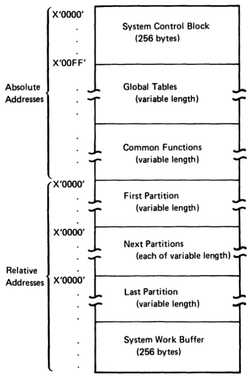
Main storage is organized into areas for system control, tables, common functions, partitions, and a system work buffer, as illustrated in Figure 1-1.
Absolute Addresses
X'OOOO'
X'OOFF'
X'OOOO'
--System Control Block (256 bytes)
Global Tables (variable length)
Common Functions (variable length)
First Partition
...
-X'O~'1
(variable length)I
Next Partitions(each of variable length) Relative
Addresses X'OOOO'
Last Partition (variable length)
System Work Buffer (256 bytes)
Figure 1-1. The Organization of Main Storage
The system control block is located in the first 256 bytes of main storage.
[image:14.618.158.407.231.613.2]Logical Device Identifiers
Logical device identifiers are 2-character IDs that allow you to symbolically address a resource independently of machine or partition configuration. The logical device IDs are stored in a resource allocation table, which is created and loaded into the global tables area by the system configuration portion of the SCP (System Control Program). The resource allocation table specifies the logical devices that can be accessed by each partition. Each resource allocation table entry contains both the logical device 10 and the physical address of that device. Whenever a program instruction requires a device address, you can specify the 2-character ID. The 5280 searches the resource allocation table for the physical address of the device with the matching I D. The 5280 uses the device at that physical address to access the data set that is available to that device.
The logical device I Ds are used only in program instructions. Do not enter a logical device 10 via the keyboard in response to a prompt that requests a physical address.
Common Functions
The common functions area contains I BM-supplied global subroutines. They can be accessed by a subroutine call from any partition. The labels and functions of these subroutines are listed in Chapter 6 under Common Function Routines.
PARTITIONS
...
"
t'
;;..
~• -I
!,i'
c' 0
..
~a.
i
~ 2,
~ N
I
i'
; a
III III
::~
i
:i'iiiCl)
;::r'"
• 0
!;i
~..
...
.":rill
..
~....
-,
o ~,
c 0
~ ~
; .
~-I
cS:
...
i'
iii' :::;'
III
=-...
... :r :r ~ .. I g ~
'0 -,
. a'
a
...
i
i
i
..
n
3'
!!. Relative Addresses X'IIII'TL
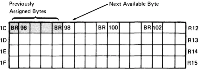
000 OOF 010 011 012 01F 020 021 OFE OFF 100 BRO 1000-1015BR8
t
1128-1143 BR16
-'-.
...
. BR120
_
....
...
_
......
2 3 4 5
BRl BR2
1016-10~1 1032-1047
BR9
1
BR10I
1144-1159 1160-1175
BR17 BR18
BR121 BR122
Storage Area
Work Buffer
-
I
6 7 8 9 A B C 0
plrtition Clntrol Arla
I
I
BR3
I
BR4J
BR5 BR61048-1063 1064-1079
.
1080-1095 1096-1111BRll
1
1176-1191
BR12
J.
1192-1207
BR13 _I
1208-1223
BR14
1
1224-1239
BR19 BR20 BR21 BR22
BR 123- BR124 BR125 BR126
E F
BR7 1112-1127
BR15
1
Partition Control Area
The partition control area contains control information that describes the program that is loaded into the partition and defines the I/O devices used in the program.
The 5280 loads this information into fixed locations within the control area, using
information from the common area and from the source program control state-ments. During program execution, the 5280 uses this control information each time it enters the partition to determine the partition status, the I/O status of the program, and the address of the next executable instruction.
Indicators and Registers
Immediately following the partition control area is an area that may be used for indicators, binary registers, and decimal registers. These bytes may be used in any desired combination of indicators and registers as described in the following para-graphs: if some of these bytes are not used for their binary register/decimal register capabilities, the unused bytes may be used as storage. Figure 1-2 shows the bytes that may be used for indicators and registers.
Indicators
The first 32 bytes of this area contain 255 one-bit indicators. In your source pro-gram, the indicators can be represented by the letter I and the indicator number. They are numbered sequentially from 10 to 1254. The first 100 indicators (10-199)
may be labeled, set, tested, and reset as your source program dictates. These indi-cators are referred to as program indiindi-cators. The remaining indiindi-cators (1100-1254)
are set and maintained by the 5280, and are referred to as system indicators. System indicators have specific meanings assigned to them, as described in Chapter 6 under System Indicators Within a Partition.
You can label program indicators with a .DCLIND control statement. When the assembler processes the .DCLIND control statement, it assigns each specified label to an available program indicator.
You can label system indicators with an .EQUATE control statement. The
.EQUATE control statement allows you to specify the number of the indicator you want assigned to each label. You could use the .EQUATE statement to label pro-gram indicators also; however, you usually don't care which propro-gram indicator is assigned to each label.
Two instructions are available to test indicators. The I F I instruction can test the indicator and perform a conditional branch. The I FIR instruction tests the indicator and performs a conditional branch, but it also resets the indicator to O. Your pro-gram can use these instructions to test propro-gram or system indicators.
You can use the instruction SON to set an indicator (1), or the instruction SOFF to reset an indicator (0). See Set Indicators under Miscellaneous Instructions in Chapter 4 for a description of these instructions.
Binary Registers
The first 256 bytes of this area may be used for up to 128 two-byte binary registers. Binary registers can be represented by the letters 'BR' followed by the register number. The registers are numbered sequentially from BRO to BR127. BRO-BR15 are used as indicators (as described in the preceding paragraphs), and BR 16-BR31 are used as system registers. The system registers are used and maintained by the 5280 during program execution and hold information as described in Chapter 6 under System Registers Within a Partition. You should not assign these registers to any other purpose. The system registers should always be reserved (see the RGL T parameter of the .START control statement). In your source program you can access the reserved registers by register number, or you can use the. EOUA TE control statement to assign them labels.
The binary registers that are not reserved by the RGL T parameter of the .START control statement can be labeled and initialized by declare control statements in your source program. Use the .DC control statement to label and initialize one binary register, or the .DCLBR control statement to label several uninitialized binary registers.
Although binary registers are 2 bytes in length, you can access either 1 or 4 bytes by defining the byte length, in parentheses, following the register number or label. If you specify a length of 1 byte (BR40(1 )), only the rightmost byte of BR40 is accessed. If you specify a length of 4 bytes (BR40(4)), the 2 bytes of BR40 and the 2 bytes of BR41 are accessed. A binary register specification with a length of 4 bytes is referred to as a binary double register.
Binary registers are often used to hold addresses. The instructions to load a binary register are described in Load Binary Register under Data Movement Instructions in Chapter 4. In your source program, you can load a 2-byte binary register with:
• An unsigned decimal integer (0-65535)
• Two EBCDIC characters
Figure 1-3 shows the hex representation of binary data in two binary registers.
High- Low· Order Order Byte Byte
~~
BR75
I
F 0 AI
BR76
I
C 0 0 FThe following examples illustrate the different ways you can refer to BR75 if you assign it the label BREG1.
BR75 BR75(2) BREG1 BREG1(2)
BREG1(l ) BR75(1)
BR75(4) BREG1(4)
Decimal Registers
}
}
}
specifies the full 2-byte binary register, which contains hexadecimal F01A.
specifies the low-order byte of BR75, which contains hexadecimal 1 A.
specifies the 4 bytes of BR75 and BR76, which contain hexadecimal F01 ACDOF.
The 3840 bytes of this area may be used for up to 240 sixteen-byte decimal registers. Decimal registers can be represented by the letter R and the register number. The registers are numbered sequentially from RO to R239. The bytes within RO and R 1 are used for indicators; the bytes within R2 and R3 are used for system registers. You should not assign RO-R3 for any other purpose. In your source program, the decimal registers reserved by the RGL T parameter of the .START control statement can be accessed by register number. Or you can use the .EQUATE control statement to assign them labels.
Decimal registers not reserved by the RGL T parameter of the .START control statement can be labeled and initialized by the declare control statements in your source program. Use the .DC control statement to label and initialize one decimal register, or the .DCLDR control statement to label several uninitialized decimal registers.
Although a decimal register is 16 bytes in length, a double decimal register of 32 bytes may be specified by defining the byte length in parentheses, following the register number or label. Decimal registers and double decimal registers are valid in decimal arithmetic and shift operations, branch operations, and table operations. All data in decimal registers is stored in EBCDIC notation. The instructions to load a decimal register are in Load Decimal Register under Data Movement Instruc-tions in Chapter 4. In your source program, you can load a 16-byte decimal
register with:
• A positive or negative decimal number (±O to 1016 -1)
• Up to 16 EBCDIC characters
The following examples illustrate the different ways that you can refer to R 120 if you assign it the label REGX.
R120 } REGX
R120(32) } REGX(32)
specifies the 16 bytes of R 120.
The contents of a decimal register may be positive or negative; the sign is deter-mined by the zone half of the byte in the units position (byte 15) of the decimal register. If the register contains a positive number, hex F is in the zone half; if it contains a negative number, hex D is in the zone half. Figure 1-4 illustrates the sign control position in a decimal register.
Sign Control Position
Byte Zone Digit
Q
o
1 2 3 4 5 6 7 8 9 10 11 12 13 14 15I··· ·l····f··· ·J···f···
·1···
·1···
·l····f···
·1····
-(····f···
·J···f···
·I····}· ..
·1
Figure 1-4. The Sign Control Position in a Decimal Register
The zone halves of the bytes are used for sign control; however, no checking is done by the 5280 to determine whether the register contents are numeric or alphabetic.
Storage
Following the registers is a variable-length area of storage. The size of this area is the size of the partition, less the 256 bytes of the partition control area and the bytes used for indicators and registers. The instruction object code is stored in this area, with the buffers, tables, formats, messages, device lOBs, control tables, data, and data structures necessary for the program.
Addressing Methods
In your source program, each byte of storage within a partition can be addressed directly, using an assigned label, or indirectly, using a displacement and a base address.
Direct labeled addressing of a storage location is accomplished by using a declare control statement to assign a label to a storage area of any length. To access this labeled area in a source program instruction, the following format is used.
label [(length)]
where:
label is the assigned label from the declare control statement. The label addresses the leftmost byte of the storage area.
Indirect base displacement addressing of a storage location is accomplished by specifying in the instruction (1) the location of the base addres and (2) the dis-placement from that base address at which the storage area is located. The length may be specified for many, but not all, instructions. To access a storage location by indirect addressing, one of the following formats is used.
[displacement] ([length], BRn) [displacement] (BRn)
where:
displacement is the number of bytes (0-255) from the base address at which the
storage area is located. If the displacement is not specified, it defaults to O.
length is the length, in bytes, of the storage area. The instruction descriptions
indicate whether or not length is allowed in the address. If a length specification is allowed, it must be followed by a comma. If length is omitted from an instruc-tion that allows a length specificainstruc-tion, the comma must be retained. If the instruction does not allow a length specification, the comma must not be included in the address.
BRn is a binary register that contains the base address. The base address is rela-tive to the start of the partition.
When a source program instruction that.has an indirect storage address is assembled, the displacement is added to the base address in the binary register. The result is the relative address of the leftmost byte of the data area. This address is placed in the object code.
Examples:
Direct: BIN1
=
STOR1(2)The contents of the byte at STOR 1 and the next byte (length is 2) are loaded into the binary register labeled BIN 1.
Indirect: BIN2
=
1 (2, BREG)The displacement of 1 is added to the address stored in the binary register labeled BREG. The contents of the byte at the resulting address and the contents of the next byte (length is 2) are loaded into the binary register labeled BIN2.
Partition Work Area
MAIN STORAGE BOUNDARY ALIGNMENT
o
000- OOF-010- BRO 1000-1015011- BR8
t
1128-1143012- BR16
:
....
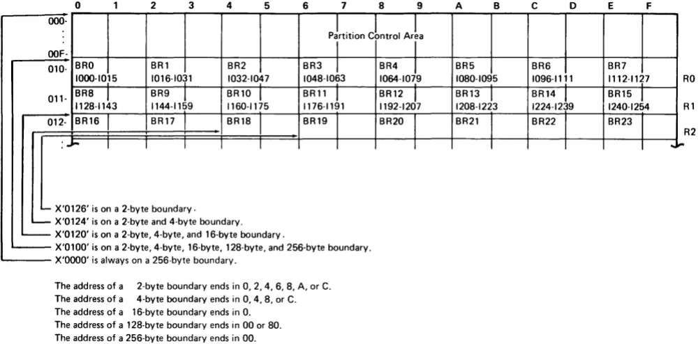
IMain storage is divided by several types of boundaries. Each type of boundary encloses an area of a specific number of bytes. Many data areas must begin on a certain type of boundary. Figure 1-5 represents a main storage partition and points out the different types of boundaries. The system configuration portion of the SCP begins each partition on a 256-byte boundary and measures the length of each partition in multiples of 256 bytes.
2 3 4 5 6 7 8 9 A B c o
pLtition Cbntrol ArL
I
I
BRl BR2 BR3
t
BR4J
BR5 BR6 1016-1031 1032-1047 1048-1063 1064-1079 1080-1095 1096-1111BR9
1
1144-1159BR10
1
1160-1175BRll
1
1176-1191BR12
J
1192-1207BR13 _I
1208-1223
BR14
1
1224-1239BR17 BR18 BR19
I
BR20I
BR21 BR22I I I I I I
- X'0126' is on a 2-byte boundary. - X'0124' is on a 2-byte and 4-byte boundary. - X'0120' is on a 2-byte, 4-byte, and 16-byte boundary.
- ' X 0100 s on a 2 byte, 4 byt ,16 byte, 128 byte, and 256 byte boundary. 'i e
~---X'OOOO' is always on a 256-byte boundary.
The address of a 2-byte boundary ends in 0, 2,4,6,8, A, or C. The address of a 4-byte boundary ends in 0,4,8, or C. The address of a 16-byte boundary ends in O. The address of a 128-byte boundary ends in 00 or 80. The address of a 256-byte boundary ends in 00.
Figure 1-5. Main Storage Boundaries
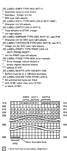
When you declare a register in your source program, the assembler places it on the next sequential boundary appropriate for the type; it places a binary register on a 2-byte boundary and a decimal register on a 16-byte boundary. It places all other data types on 1-byte boundaries unless you specify a boundary. When you are build-ing a storage structure, you may want to specify a boundary. When the 5280 assembler processes your source control statements and sets up these data areas, it skips over any storage bytes between the current location and the next appropriate boundary in order to observe the boundary restrictions. These bytes cannot be used by your program. Your assembly listing indicates how many storage bytes are lost due to boundary alignment. See the examples following the description of the .DC control statement in Chapter 3 for an illustration of boundary alignment.
E F
BR7
1112-1127 RO
BR15
1
1240-1254 RlBR23
R2
[image:22.613.60.560.196.443.2]BLANKS, CONSTANTS, AND CODING SYMBOLS
In your source program, you may specify optional blanks before or after an equal sign, arithmetic operator, or parenthesis. Blanks may follow a comma but must not precede a comma. Blanks are not allowed within a field; however, one or more blanks must separate fields if no other delimiter is used.
A constant may be specified as a decimal value, a hexadecimal value, a binary value, or a character. A constant may also be equated to a label; the label can be specified in an instruction that accepts a constant. Decimal digits are simply written as digits. Binary, hexadecimal, and character data are prefixed by a capital letter (B, X, and C respectively) and enclosed in single quotes. For character data the capital C is optional. Do not leave a blank between the capital letter and the first quote.
n Decimal digits
X'I' Hexadecimal digits; I
=
O-F B'I' Binary digits; I=
1 or 0CT EBCDIC characters; I
=
any valid EBCDIC characterSymbols Used in This Manual
The symbols used in this manual are of two types, syntax symbols and statement symbols. The syntax symbols are used to illustrate syntax and are not to be used in writing your source programs. The statement symbols are a part of the language and must be coded as shown.
Syntax Symbols
Syntax symbols are not to be coded in the source program.
Symbol
[ ]
{ }
Definition
Brackets enclose optional item (s) to be used or not, at your discretion.
Braces enclose two or more items from which you must select one.
Three dots indicate that the preceding can be repeated.
b Lowercase letters represent information you must supply. (You label must substitute your own values for the lowercase terms.)
n Represents an unsigned decimal number.
±n Represents a signed decimal number.
0-9 Represents a range of numbers from which one number can be selected. (The dash is not coded.)
In Represents an indicator, which can be referred to by label or number.
BRn
Rn
BRa Rb
constant
Represents a binary register, which can be referred to by label or number.
Represents a decimal register, which can be referred to by label or number.
When more than one register may be used in a statement, the letters a, b, and c may replace the n to more clearly demonstrate the posi-tions in the statement that the different registers may occupy.
Statement Symbols
Statement symbols must be used in an assembler source program as shown in the syntax iilustrations:
Symbol
( )
S
LABEL
Definition
Colon is used after symbolic labels.
Semicolon delimits statements.
Point, or period, begins control statements.
Equal sign causes the value of the data area on the left of the equal sign to be changed according to the value of the data area on the right of the equal sign.
Parentheses enclose certain parameter values.
Single quotes enclose literals and are used to specify numeric data other than decimal. The use of single quotes is interchangeable with the use of capital C and single quotes. For example, C'abc' and 'abc' produce the same results.
Comma separates parameter values.
Chapter 2. Programming Concepts
This chapter discusses various data areas that are set up according to your control statements and are used by the 5280 during program execution. The discussions often refer to the control statements that generate the areas and the instructions that use the areas during program execution. Each control statement is described in Chapter 3; each instruction is described in Chapter 4.
TABLES
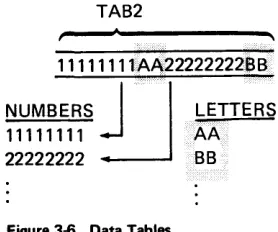
Tables play an important part in 5280 assembler programming. Two kinds of tables may be set up and used by your program: data tables, which are set up by .TABLE control statements, and label tables, which are set up by .LABTAB control statements. Also, the assembler builds system tables, which are used by the 5280 during program execution. These system tables allow you to refer to a data area with a label; the 5280 converts the label to an index that points into a system table and locates the address and parameters of the area.
System Tables
When the assembler processes control statements that set up as tables, formats, or prompts, it places the address of each table, format, or prompt in a table. This table of addresses is a system table, and is used by the 5280 during program execution. System tables are stored in the partition storage area. You can specify the address of the system tables by using the .SYST AB control statement in your source pro-gram. Otherwise, when the assembler encounters the .END control statement, it stores the system tables at the addresses immediately following the last address that contains program object code. The address of each system table is stored in the partition control area. The control statements that generate a system table argu-ment are listed below, with the system table into which the arguargu-ment is entered.
System Table Control Statements
Table control .TABLE
Edit format control . FMT series (each series = 1 argument)
Screen format control .SFMT series (each series = 1 argument)
Prompt control .DC TVPE=PRMT
When a source instruction refers to a prompt, table, duplicate field, store field, or format, the insiruction specifies only the !abe!. The 5280 uses this label to find
the system table entry; the system table entry provides the address and other control parameters. The system table entries are stored sequentially, in the order they occur in the source program. Except for the prompt system table, the first entry in a system table is at index 0; for the prompt system table, the first entry is at index 1. The assembler places the table index into the object code instruction. This method requires only 8 to 10 bits of the 4-byte object code to provide the address and parameters of the requested data area. The .SYSTAB control state-ment description in Chapter 3 describes how to specify the labels and addresses of the system tables.
Data Tables
Contiguous fields of related data can be referred to as a data table. In your source program, you can allocate and initialize the fields of a data table by using .DC control statements. After you have allocated the fields, you must use the .TABLE control statement to structure the fields into a table. The first argument in a data table is at index 1. You may have up to 128 tables within a partition. You must include one .TABLE control statement for each table in your source program.
You can use instructions in your source program to request that the 5280 search, read, or write the entries in a data table. See Table Instructions in Chapter 4 for a description of these instructions.
Data tables can be fixed length or variable length, according to your .TABLE control statement. See the .TABLE control statement definition in Chapter 3 for an example of .DC and .TABLE control statements that build a variable length table.
Label Tables
Label tables are tables that contain addresses; they are used by your program to make indexed branches and indexed subroutine calls. In your source program you use a .LABTAB control statement to set up a label table.
The parameters of the. LABT AB control statement specify the labels of the sub-routines or instructions you wish to enter into the label table. The address of the first label specified in the .LABTAB statement is entered at index 0 in the label table, the address of the second label is entered at index 1, and so on. When you code a GOT AB or CAL L TB instruction, you specify (1) the label of the label table and (2) the label table index of the subroutine or instruction you wish to execute.
DATA TYPES
Each source instruction and control statement requires specific types of data to be used as operands. For some operands only one type of data is accepted. For example, the format operand of the ENTR instruction requires a screen format specification; no other type of data is accepted. For other operands more than one type of data may be specified. For example, the operand of the ZONE instruction may be specified as a decimal register or as a constant.
The following data types can be used in the instruction and control statement operands.
• Label or number of an indicator
• Label or number of a binary register
• Label or number of a decimal register
• Label of an instruction
• Label of a data storage area (from a STOR type .DC)
• Label of a prompt (from a PRMT type .DC)
• Label of a duplicate area (from a MDUP type .DC)
• Label of an edit format
• Label of a screen format
• Number of a data set
• Index of a table
• Constant
SUBROUTINES
A program can call any subroutine that is stored within the partition. Calls to routines in the common function area are discussed under Common Function
Routines in Chapter 6.
Two source instructions can be used to call a subroutine: the CALL and CALL TB instructions. These instructions are described in Chapter 4 under the Subroutine
Call and Return instructions. A CALL instruction must include a label or a binary
iilt: CALLiS instruction is used to make an indexed branch through <l label table. The label table must be set up and labeled by a .LABTAB control statement. You include this label table and a binary register when you write the CALL TB instruc-tion. The binary register contains the index of the subroutine you wish to call. The first entry in the label table is at index O. When the CALL TB instruction is
executed, the call is made to the subroutine at the specified index into the label table. If you use a separate subroutine for each external status condition, the 5280 uses this method to call the appropriate external status subroutine. The 5280 uses BR23 to hold the index into the external status subroutine label table.
The Partition Subroutine Stack
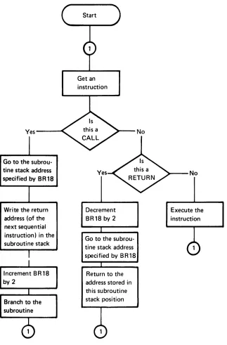
Whenever a subroutine call instruction is executed, the address of the next sequential instruction is assumed to be the return address and is stored into the partition stack. The partition stack is a system table with 2-byte entries, located in partition storage. You may use the .SYSTAB control statement in your source program to specify the address and size of the partition stack. Otherwise, when the assembler encounters the .END statement it locates the beginning of the partition stack in the address following the last address that contains program object code or system tables. In either case, it stores the address of the beginning of the partition stack in BR18, which is referred to as the stack pointer. When the first subroutine call is executed, the 2-byte return address is placed in storage at the address indi-cated by BR18. Then the address in BR18 is incremented by two, so that it points to the next available stack entry. If another call is executed before a return is made to the first call, the return address for the second call is placed in the address indicated by BR18, and BR18 is incremented by two. In this way, you can have nested subroutine calls. You must remember, however, that each nested call adds another 2-byte entry to the partition stack. If the partition stack extends beyond the end of the partition, a program check error results.
Subroutine Returns
External status subroutine returns depend upon the particular external status condition and are described under External Status and Error Conditions in this chapter.
Other subroutines end with a RETURN instruction. When this instruction is exe-cuted, the content of BR18 is decremented by two so it points to the last address entered into the partition subroutine stack. If the RETURN instruction includes a binary register, an indexed return is made. The content of the binary register is added to the address pointed to by BR18, and control returns to the resulting address.
Yes---~
Go to the subrou-tine stack address specified by BR18
Write the return address (of the next sequential instruction) in the subroutine stack
Increment BR18 by 2
Branch to the subroutine
Get an instruction
Yes
Decrement BR18 by 2
Go to the subrou-tine stack address speci tied by B R 18
[image:30.612.149.472.56.547.2]Return to the address stored in this subroutine stack position
Figure 2-1. Overview of Subroutine Calls and Returns
No
~--No
THE STATUS LINE
The top line of the data station screen normally displays the status line. The 5280 maintains status line fields, which communicate status information to the operator. Figure 2-2 illustrates the status line fields.
Position
2 3 4 5 6 7 8 9 10 11 12 13 14 15 16 17 18 19 20 21 22 23 24 25 26 . . . 32
p C C C C
s
R R H Hp C C C C
s
R R>
H Hp C C C C E E E E
s
R R H Hp C C C C E E E E
L L
N N N N N N N No
0 ... 0Key
P is the partition number. C is the current position counter. E is the error or condition code. S is the field shift.
>
is the insert mode symbol.R is the positions remaining in the field. H is the hex value of the current position. L is the logical device 10.
N is the program name (first 8 characters).
o
is the data set name.Figure 2-2. The Status Line Fields
The Partition Number
The partition number is maintained only during an attach or detach operation. Upon completion of a successful attach operation, this status line field contains the partition number of the attached partition. Upon completion of a successful detach operation, this field contains the partition number of the foreground parti-tion that is permanently associated with the keyboard.
The Current Position Counter
The current position counter is maintained only during the processing of an ENTR command. This status line field contains the value of the position counter. The value is automatically updated with each keystroke. The value reflects the current position, relative to: (1) the beginning of the I/O buffer, (2) the first posi-tion on the screen, (3) the first posiposi-tion of the record, or (4) the first posiposi-tion of the field. The CNTR parameter of the .KBCRT control statement determines which value is maintained in the counter.
Mode
Normal Entry
Normal Entry, Insert Mode Keystroke
Error
The Error Code
The error code field of the status line contains the error code of the current error. It is maintained by the 5280 to reflect all errors. If your program issues a keyboard operation to send an error code to the status line, you may place the code in positions 1-65 of the status line; however, the code is normally placed in positions 3-11.
The Field Shift
The field shift position of the status line is maintained only while an ENTR com-mand is being processed. It contains the symbol that reflects the keyboard shift for the current field or subfield.
The Insert Mode Symbol
The insert mode symbol is maintained only during the processing of an ENTR command in insert mode, after the operator has pressed the Ins (Insert) key.
The Positions Remaining in the Field
This status line field is maintained only while an ENTR command is being processed. It reflects the number of field positions remaining to be entered in the current input field. If the value is greater than 99, two asterisks (**) are contained in the status line field.
The Hex Value of the Current Position
The hex value is maintained on the status line only while an ENTR command is being processed. It is the hex value contained in the I/O buffer position that corre-, sponds to the current position of the cursor.
Nondisplay of the Status Line
Certain applications may require the use of every line on the screen. For these applications, the DISPEX instruction can remove the status line from the screen so the top line can be used to display data or prompts, or both. The 5280 maintains the status line whether or not it is displayed on the screen. If an error occurs when the status line is not being displayed, the DISPST instruction can temporarily replace the current top line with the status line in order to communicate error information to the operator. Or the FUNC parameter of the .KBCRT control state-ment can specify that the 5280 determines whether the status line is being displayed whenever an error occurs; if it is not, the 5280 displays it, then returns the top line when the error is reset. The data from the top line is not lost and may be returned to the screen after appropriate error recovery has been accomplished.
EXTERNAL STATUS AND ERROR CONDITIONS
When an I/O error condition or a condition that requires operator intervention occurs, the 5280 generates an appropriate condition code and places it into the lOB of the data set that was being processed when the condition occurred. The condition code is made up of four digits that describe the condition:
• Device reporting the condition (first digit)
• Category of the condition (second digit)
• Condition number (third and fourth digits)
The device digits are:
Digit Device
o
5280 controller1 Keyboard/display
2 Printer
3 Diskette
4 SNA communications access method
5 BSC communications access method
9 Program
The category digits are:
Digit Device
o
Communications completion codes1 Operator intervention required
2 Hard error (not retried)
3 Error that has been unsuccessfully retired
4 lOB error
5 Soft error (has been successfully retried)
6 Exception condition
7 Warning message, program execution may continue
8 Reserved
9 Software termination
The last two digits of the condition code are the condition number. The condition number specifies the condition and varies depending upon the device and category.
The following information concerning the condition is placed into system binary registers within the partition when the condition occurs.
Register
BR19
BR20
Information
Used only with keyboard/display external status, this register con-tains the relative address of the field in the I/O buffer that holds the current record. The address is relative to the beginning of the parti-tion and is valid only when BR21 contains a field specificaparti-tion.
Used only with keyboard/display external status, this register con-tains the absolute address of the current field in the screen refresh buffer and is valid only when BR21 contains a field specification. The screen refresh buffer is located within the keyboard/display unit and holds the data that appears on the screen.
BR21 Used only with keyboard/display external status, this register con-tains a control specification or a field specification. If it concon-tains a field specification, it also contains the length minus one of the current field in the I/O buffer. See Keyboard/Display External Status in Chapter 6 for the format of the contents of this register.
BR22
BR23
Used with all external status except keyboard/display. this register contains the relative address of the last lOB to report external status.
Used with all external status, this register contains the index of the current external status condition. This index can be used by your program as the index into your external status subroutine label table. Except for keyboard/display external status, this index is the cate-gory digit from the condition code. See Keyboard/Display External Status in Chapter 6 for information about this index for keyboard/ display external status.
If you write subroutines to handle certain external status conditions, such as the keyboard/display external status conditions, your program may use the data in these registers. Do not change the data in the system registers.
KEYBOARD DATA ENTRY
The siaius iille displays data EntPI inform<ltion such as the current keying position,
the number of positions remaining to be filled in the current field, and the key-board shift for the field.
The operator can select functions, such as duplicate or skip, by pressing the appro-priate function keys. You can let the 5280 process keyboard functions, or you can include your own routines to handle these functions. See the Functions Reference Manual for more information about the keyboard functions.
Modes of Entry
The 5280 supports three basic modes for data entry:
• Enter mode, for initial data entry
• Update mode, for inspection and modification of previously entered data
• Verify mode, for having data checked for accuracy and making necessary corrections
In addition to these basic modes, rerun mode or display mode can be selected by your program to perform special functions. You can select one of these five modes with the MODE parameter of the .KBCRT control statement. (See .KBCRT Con-trol Statement in Chapter 3.) Insert mode or field correct mode is automatically selected by the 5280 when the appropriate keystroke is entered.
Enter Mode
When the 5280 executes an ENTR command in enter mode, each data character is displayed on the screen and placed into the I/O buffer as it is entered. Prompts, constant inserts, duplicate fields, skip fields, and display attributes are displayed when the cursor moves to the first position of the field or to the attribute position; these positions are specified in the screen format. Constant inserts are also placed into the I/O buffer as they are displayed. When the complete screen format has been processed, the I/O buffer holds the constant inserts and the newly entered data.
Update Mode
Verify Mode
When the 5280 executes an ENTR command in verify mode, prior instructions in your program must have placed a previously-entered record into the I/O buffer. The 5280 displays the prompts and display attributes as for enter mode, according to the screen format. It does not display the contents of the I/O buffer. As the operator enters a data character into a record field position, it is verified against the contents of the corresponding field position in the I/O buffer. If the newly entered
character matches the original character, which is in the I/O buffer, it is displayed on the screen and the cursor moves to the next position. If the newly entered character does not match the original character, the cursor remains at the character position, the original character and the remainder of the field in the I/O buffer are displayed, and a verify mismatch error is reported. The operator must press the Reset key, then enter either the character displayed above the cursor or reenter the character that caused the mismatch. If the character that is displayed above the cursor is entered, the remainder of the field is removed from the screen and the cursor moves to the next position. If the character that caused the mismatch is reentered, that character is displayed above the cursor and replaces the original character in the I/O buffer. A verify-correction keystroke counter is incremented (see Keystroke Counters jn Chapter 6) and the cursor moves to the next position. If the character entered is neither the original character nor the character that caused the mismatch, another verify mismatch error is reported. If the operator backspaces over a data position on the screen, the position is blanked and must be
reentered and reverified.
Rerun Mode
When the 5280 executes an ENTR command in rerun mode, no data or prompts are displayed on the screen. The status line counters, keyboard shift, and hex display information is not maintained. The entire screen format is processed, except that a clear-screen function that is specified at the start or end of the format is ignored. Character and field edit checks are bypassed. Auto duplicate, auto skip, and main storage duplicate and store functions are performed if the auto-dup}3kip switch is turned on or if the field has the AA (absolutely automatic) attribute speci-fied in the screen format. Constant inserts are placed into the I/O buffer. When an RG (return to program) exit specification is encountered in the format, the appropriate external status condition occurs.
Rerun/Display Mode
When the 5280 processes an ENTR command in rerun/display mode, the prompts, display attributes and the contents of the I/O buffer are displayed as for update mode. The status line information is maintained. Character and field edit checks are bypassed. Auto duplicate, auto skip, main storage duplicate and store, and RG functions are performed as for rerun mode.
Display Mode
When the 5280 executes an ENTR command in display mode, prior instructions in your program must have placed a previously-entered record into the I/O buffer. The 5280 displays prompts, display attributes and the contents of the I/O buffer. The display attributes and prompts are determined by the screen format. The cursor is not displayed, and no data can be entered. If a buzz or clear-screen func-tion is specified at the end of the screen format, it is ignored. When the 5280 has processed the complete screen format, the external status condition for record advance (condition 6) occurs.
You can use display mode to inspect the prompts and display attributes of a screen format. Do not confuse display mode with rerun/display mode.
Insert Mode
Insert mode is initiated when the operator presses the Ins key. Insert mode is valid only when an ENTR command is being processed. When the Ins key is pressed, the insert mode symbol is displayed on the status line. When the operator presses a data key, the data character is inserted into the field at the current cursor position. All field positions to the right of the cursor, and the cursor and character above the cursor, are shifted one position to the right. Insert mode is canceled when the operator presses the Reset key.
Field Correct Mode
Field correct mode is selected by the 5280 when it is processing an ENTR in verify mode and the operator presses the unshifted Corr key. The cursor moves to the first position of the field, and the field is filled with blanks in the I/O buffer and on the screen. The operator can then enter data into the entire field as for enter mode. The character and field edit checks are performed. When the cursor exits the field in the forward direction, the 5280 returns to verify mode. The field can now be verified.
AUTOMATIC FUNCTIONS
Auto Enter
If you specify auto enter in your .KBCRT control statement, the 5280 automati-cally performs a record advance function when the operator enters the last input position of a record.
If you do not specify auto enter, the 5280 sets the system in the awaiting record advance state when the operator enters the last position of a record. The operator must then press the Enter key or Rec Adv key to initiate a record advance function.
Auto Duplicate/Skip
If you specify auto duplicate/skip in your .KBCRT control statement, the 5280 automatically processes any field that is defined in your program as an auto duplicate or auto skip field. When the cursor moves to the first position of an auto duplicate field, the 5280 duplicates data into the field from the area specified by your program. (See Field Definitions later in this chapter for more information about duplicate fields.) When the cursor moves to the first position of a skip field" the 5280 fills the field with blanks and then moves the cursor to the first position of the next field.
If you do not specify auto duplicate/skip in the .KBCRT control statement, a dupli-cate field or skip field is processed as for a manual field. In order to initiate the duplicate or skip function, the field must have also been specified as absolutely automatic in the program, or the operator must press the Dup Skip key. (Software must provide support for this key.)
Alternate Record Advance
If you specify alternate record advance in your .KBCRT control statement, when the operator presses the Enter key or Rec Adv (Record Advance) key the processing of the current record stops. Any specifications for fields or screen control that is defined in your program for positions between the cursor position and the end o