A Single-Phase Ac-Dc Converter with Improved Efficiency Using Atmega 8 Microcontroller
Full text
Figure

Related documents
In [3], a new inverter is presented as a boost inverter where the required output voltage can be lower or greater than the input dc voltage by connecting the load
In theory if we increase the duty ratio to 0.95 we get the output voltage 20 times the input voltage according to the output voltage equation of boost converter.. The
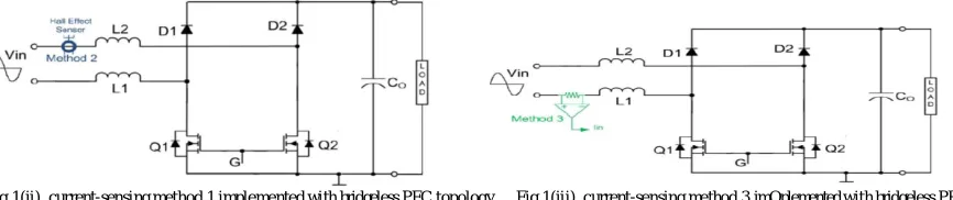
Regardless of whether the ac grid voltage source is operating in the positive half-cycle vs > 0 or the negative half cycle vs<0, the converter
topology, the actual output voltage is compared to the desired output voltage and the difference (error) is used to adjust the PWM duty cycle to control the
The simulation result of Output voltage in buck mode dc (sum of duty ratios=2) is shown in Fig.15.An output voltage of four input dc-dc buck converter with constant equal input
The buck boost converter will either increase or decrease the output voltage with respect to the input voltage based on the duty cycle.The I-V and P-V
This high ratio dc-dc converter topology is able to convert its input voltage into very small/big output voltage without need to operate its switching devices in the extreme
Matrix converter is single stage converter which converts AC input power to variable voltage and frequency output AC power without using DC-link capacitor.. As DC-link
