Vol. 4, Issue 1, January 2015
Design of VFD Drive for a 3-Phase Induction
Motor
M.Deepa
Assistant Professor, Department of Mechatronics Engineering, Bharath University, Chennai,India.
ABSTRACT: The main aim of the project dealt with the concept of speed control of a three-phase induction motor with energy saving. To do so, a VFD (Variable Frequency Drive) is used for controlling the speed of a three-phase induction motor with variable load attached to the motor. It certainly leads to the best performance and high efficiency of the induction motor. In recent years, a major issue that is threatening Tamil Nadu for the past two years is the shortage of electricity. In such case, the unwanted energy should be saved. As a result, the implementation of VFD helps in saving a large amount of energy by reducing the sudden jerks happening at the starting of the motor. An experimental setup is designed using VFD & without VFD and the outcomes are displayed to prove the concept of energy saving.
KEYWORDS: Variable frequency drive, three-phase induction motor, pulse width modulation, insulated gate bipolar transistor.
I. INTRODUCTION
A new trend to adjust the speed of a three phase induction motor is by using variable frequency drives. Generally, an induction motor can run only at its rated speed when it is connected directly to the main supply. However, many applications need variable speed operations. In most of the applications the input power is directly proportional to the cube of motor speed. In certain applications like induction motor-based centrifugal pump, a speed reduction of 20% results in an energy saving of approximately 50%.
In today’s modern era, driving and controlling the induction motor efficiently are the two important constraints. With the new innovations developed in the semiconductor fabrication technology, the size and the price of semiconductors have drastically gone down, which means that the end user can replace an energy inefficient mechanical motor drive and control system using a Variable Frequency Drive (VFD). The VFD not only controls the motor speed, but can improve the motor’s dynamic and steady state characteristics as well. In addition, the VFD can reduce the system’s average energy consumption.
II. RELATEDWORK
Research to study variable frequency drive and its energy savings Paper tells about Simulation and circuit analysis of result then How to change of motor speed and Waveform analysis of speed torque.voltage, current.From the paper “monitoring and control of a variable frequency drive using PLC and SCADA” I learn the function of PLC(PROGRAMMABLE LOGIC CONTROLLER) and SCADA(SUPERVISORY CONTROL AND DATA ACQUISITION SYSTEMS).
Control platforms:Most drives use one or more of the following control platforms:
PWM V/Hz scalar control
PWM field-oriented control (FOC) or vector control
Vol. 4, Issue 1, January 2015
These motor drives are designed to be used in conjunction with a 3-phase induction motor. Because these motors typically only have an on/off state of operation, a VFD is needed if multiple operation speeds are desired. Also, apart from selectable speeds, the efficiency of the overall system is increased due to the fact that the motor only sees the necessary amount of input power to achieve desirable output power. Also, the motor can be slowly brought up to speed, eliminating huge start-up current spikes. The testing was broken down into two categories: small and large scale power circuits. The controlling circuit was kept the same.
The small scale testing was essential because the power handling capabilities of the circuit at its initial prototype levels was not possible. Due to the large power demands, the large IRFP360PBF MOSFETs from International Rectifier were traded in for smaller switches IRF510 from International Rectifier as well. The DC rails were reduced to 10V and obtained from a DC power supply instead of a rectified signal. Testing for the drive was done for a range of 40-80 Hz. Key nodes were probed and their signals analysed. The captures included in this report are the result of the small scale testing. While a complete large scale test was not completed due to a lack of components (PCB), the small scale test was a success. All the signals behaved as predicted. Additional testing is required, but must be done using a combination of PCB to ensure proper connections as well as proper power capabilities.
You can divide the world of electronic motor drives into two categories: AC and DC. A motor drive controls the speed, torque, direction and resulting horsepower of a motor. A DC drive typically controls a shunt wound DC motor, which has separate armature and field circuits. AC drives control AC induction motors, and-like their DC counterparts-control speed, torque, and horsepower.
Three different optimization techniques we used, there are, A. Conventional Optimization Techniques
B. AI Based Optimization Techniques C. NIA Based Optimization Techniques
Design Optimization of Induction Motor explains the Conventional Algorithms and AI and NIA Based Algorithms. Conventional Algorithms tells about the Effect of different step size, Effect of constraints, Effect of changing objective function.
VF control provides a simple and cost efficient method for open-loop speed control of 3-phase induction motors. In future we can use low-cost VF solution can be implemented using the PIC16F7X7 family of devices. With three dedicated PWM modules implemented in hardware, it is ideal for controlling 3-phase induction motors. Additional on-chip resources, like multiple timers and ADC, allow users to easily implement safety and control features, such as current and voltage protection and configurable acceleration and deceleration time.The variation in speed, the torque-speed characteristics of the VF control reveal the following:
• The starting current requirement is lower.
• The stable operating region of the motor is increased.
•At base speed, the voltage and frequency reach the rated values. We can drive the motor beyond the base speed by increasing the frequency further.
Vol. 4, Issue 1, January 2015
III.VARIABLEFREQUENCYDRIVE(VFD)
Variable Frequency Drive (VFD) can be used to control the speed of three-phase induction motor. A variable-frequency drive is a system equipped for controlling therotational speed ofan alternating current (AC) electric motor by controlling the frequency of the electrical power supplied to the motor.
The three basic components of the VFD are:
Rectifier
DC Bus
Inverter A.VFD Types:
The following list gives mechanical, electrical and hydraulic VFD examples (many have a considerable mechanical content needing regular maintenance):
1. Mechanical Drives.
a. Adjustable sheave belt drive. b. Clutch.
c. Traction drive. 2. Electrical Drives.
a. Eddy—current clutch. b. DC (rotating and solid state). c. Solid state Vac.
d.Multi-speed motors. 3. Fluid drives.
B.Why Buy a VFD?
Mechanical, electrical, and fluid power adjustable speed drives are available that offer some of the aforementioned benefits.
None combine all of the advantages of a VFD:
1. Variable speed and flow capability with standard induction motor. a. Improved process control.
b. Energy savings.
2. Reduced voltage starting characteristics. a. Soft start/smooth acceleration.
b.Reduces power supply problems in the facility. c. Reduces motor heating and stress.
3. Used with standard AC induction motor.
For industrial purpose the power is to be delivered for larger distance hence AC power supply is required to drive the motors. The rectifier in a VFD is used to convert incoming ac power intodirect current (dc) power. There are 3 pair of rectifier combination is used for converting 3 phase AC into DC.Normally 6,12 or 18 diodes will be used to serve this purpose. Rectifiers can be built using diodes, silicon controlled rectifiers (SCR), or transistors to rectify power. After the power flows through the rectifiers it is stored on a dc bus. The dc bus contains capacitors to accept power from the rectifier and stores it and finally delivers that power through the inverter section.
Vol. 4, Issue 1, January 2015
depending upon frequency. Varying the frequency output of the VFD controls motor speed. The speed of the motor is given by,
Speed (rpm) = frequency (hertz) x 120 / no. of poles IV.VFCONTROL
The speed of the induction motor is directly proportional to the supply frequency and the number of poles of the motor. Since the number of poles is fixed by design, the best way to vary the speed of the induction motor is by varying the supply frequency. The torque developed by the induction motor is directly proportional to the ratio of the applied voltage and the frequency of supply. By varying the voltage and the frequency, but keeping their ratio constant, the torque developed can be kept constant throughout the speed range.
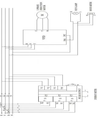
V.EXPERIMENTAL SETUP USED
The experimental setup used for energy saving using VFD has been given in fig 1. The various components used are variable frequency drive(motor,controller,operator interface, VF control),3-phase induction motor, energy meter, current transformer,Timer,Clamp meter.
VI.WORKINGPRINCIPLE A.Interaction Of Stator And Rotor:
Speed and torque control of a 3-phase induction can be achieved using VF control. The two basic parts of the motor are the rotor and stator which work through magnetic interaction. The stator is the iron pieces wound in a specific pattern to provide a north to south magnetic field. Likewise there will be number of pole pairs for generating alternating magnetic field. The number of poles and the frequency applied determine the speed, but the formula includes an effect called "slip." Slip is the difference between the rotor speed and the rotating magnetic field in the stator. Electronic VFDs are the cost effective one which is used in this experiment.
B.Working Of The Experimental Setup:
Connect all the components according to the circuit diagram.Intially without VFD the circuit is enabled and the starting and running current is measured. Next the experiment is conducted with the usage of VFD by writing the energy saving program in it. Due to the attachment of VFD the motor starts gradually from lowest to highest. After conducting the experiment the outcomes are posted in the table given below in Table No.1
VII.ENERGY SAVINGS USING VFD
An auto energy saving operation is available in VFD, which automatically controls the supply voltage to the motor to minimize the total power loss of motor and inverter. This feature may not be effective depending upon the motor or load characteristics. Therefore, we have checked the advantage of energy saving before actually applying this feature to our power system. This feature applies to constant speed operation only. During acceleration/deceleration, the inverter will run with manual torque boost or auto torque boost, depending on the F37 data. If auto energy saving operation is enabled, the response to a change in motor speed may be slow. This feature may not be applicable for such a system that requires quick acceleration / deceleration. The auto energy saving is used only where the base frequency is 60 Hz or lower. If the base frequency is set at 60 Hz or higher, there will be a little or no energy saving advantage. The auto energy saving operation is designed for use with the frequency lower than the base frequency. If the frequency becomes higher than the base frequency, the auto energy saving operation will be invalid.
A.User Benefits:
One machine covers all applications.
Lower spares cost.
Fewer different variants for technicians to work with.
Possible general reduction is costs: higher volume production.
Vol. 4, Issue 1, January 2015
B.Advantages:
Long life.
High protection levels available.
High efficiency: 80%+.
Readily available replacements world-wide.
Minimal moving parts therefore low maintenance cost.
High starting torque, suitable for wide variations of applications.
Simple to reverse.
Low cost.
C.Benefits Summary:
Improved control.
Reduced plant wear.
Quieter operation at low load.
Reduced complaints.
Lower operating costs.
Typical payback period is less than 2 years.
D.Why Buy a VFD?
Mechanical, electrical, and fluid power adjustable speed drives are available that offer some of the aforementioned benefits.
None combine all of the advantages of a VFD:
1. Variable speed and flow capability with standard induction motor. a. Improved process control.
b. Energy savings. 2. Reduced voltage starting characteristics. a. Soft start/smooth acceleration.
b.Reduces power supply problems in the facility. c. Reduces motor heating and stress.
3. Used with standard AC induction motor.
F.VFD Features:
Auto restart.
Speed search.
Over speed.
Over torque protection.
Stall prevention.
Analog or digital control.
Vol. 4, Issue 1, January 2015
Fig 1.Circuit diagram
From the table it is predictable that the starting current required by the three phase induction motor varies drastically if the VFD control is been used.
Table No.1Energy comparison with and without VFD Process Speed
(rpm)
Starting Amps Running Amps
Volts
3-Phase Induction Motor
without VFD
1500 1.3 A 0.5 A 430V 3-Phase
Induction Motor with VFD
Vol. 4, Issue 1, January 2015
VIII.VFDAPPLICATIONS
Industry segments are important, because many applications are industry specific. Some classic VFD applications for various industries are provided below:
HVAC, fans and pumps.
Food Processing: agitators, mixers, conveyors for food transport, packaging and bottling, preparation machines (slicers, dicers, choppers), extruders, fans and pumps.
Petrochemicals: deep well pumps, oil field recovery, local distribution pumps, fans and pumps.
Mining and Metals: reheat furnaces, cooling beds, run in/out tables, fans and pumps.
Pulp and Paper/Forest Producers: washers, kilns, slitters, chippers, saws, sanders, peelers, de-barkers, fans and pumps, vacuum removal systems.
Machine Tool: replace spindle drives, grinders, saws, lathes, tool positioning drives, balancing machines, fans and pumps.
Transportation: material handling conveyors, cranes and hoists, small vehicle drives, fans and pumps.
Any machine or process that can be improved by varying speed or flow is a candidate for a VFD.
IX.CONCLUSION
Hence the modern world which seeks a renewable energy source for the electricity requires the concept of power which can be achieved using the concept of VFD control for the speed control of 3-phase induction motors. A VF solution can be implemented using Variable Frequency Drive with PWM technique is suitable for crisp control of motors. In industries where motors and pumps used to satisfy all basic necessities can used the VFD controlled motors lead to higher energy saving. Also the additional resources used along with VFD like timers and run lamps provide greater safety and security measures against sudden jerk in current and voltage. The similar experimental setup can be built using MATLAB-SIMULINK which helps to build a control system with VFD for large scale purpose.
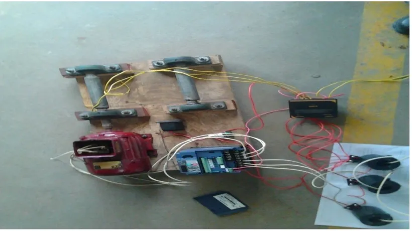
X.SNAPSHOT
The practical experimental setup to show the concept of energy saving of a three phase induction motor with and without VFD.
A.Vibration:
Although a modern VFD produces good quality current waveforms, there is a small amount of additional vibration produced at the motor. Thus, there is potential for small reduction in the motor life expectancy. However, motors are often installed on inadequate frames or machinery that has a tendency to vibrate. Consequently, the life expectancy of the winding is affected far more by the installation than the VFD.
B.Ventilation:
The installation of a VFD should have no affect on motor ventilation, as this is a purely mechanical function. However, a VFD tends to cause motors to run slightly warmer than they would if driven from a commercial power supply: typically 5 degrees Fahrenheit. Normally this is well within the motor design limits and there are no adverse effects from the small increase in temperature.
C.Rated Temperature Rise:
Typically, motors are designed to produce a 176°F temperature rise at full load with nameplate conditions, in an ambient temperature of 104°F. As additional temperature rise caused by VFD application is only 5°F and experience shows that most motors are selected with 80% of design capacity and rarely run with an ambient temperature of 104°F. Again there is little effect on the life expectancy of the motor, when driven by a VFD.
D.Load (Duty Cycle):
Vol. 4, Issue 1, January 2015
E.Power Supply Frequency:
The motor design frequency is usually 50 or 60 cycles. When a VFD drives a motor, it is usually to control the motor speed.
Fig 2.Experimental setup built
F.Terminal Voltage:
VFD control of the motor terminal voltage is direct. The VFD overall control strategy includes design to provide this function. As motor terminal voltage has a major impact on motor performance, great effort has been made by manufacturers to optimize voltage control under all conditions.
G.Further Protection:
Under all operating conditions the VFD monitors the speed and load imposed on the motor. A model of these conditions is continuously updated and checked against standard acceptable limits. In the event that these limits are exceeded, the motor is in an overloaded condition. Unless this overload is removed, the VFD takes the decision to trip the drive to safeguard the motor. If this motor model does not to provide the desired protection level, the VFD can take direct measurement of motor temperature via internal thermistors.
REFERENCES
1. R.Krishnan, Electric Motor Drives (Modeling, Analysis, and Control), Prentice Hall, Inc. 2001.
2. Ned Mohan, Torre M. Undeland, William P. Robbins, Power Electronics Converters, Applications and Design, Wiley, New York. 1995.
3. Richard Valentine, Motor Control Electronic Handbook, McGraw-Hill, New York,1998.
4. Sigh, M. D. and Khanchandani, K. B. Power Electronic, Tata McGraw-Hill Publishing Company Limited, New Delhi, 2000.
5. Ham N. J., Hammerton C. J. and Sharples. D.Power Semiconductor Applications, Tata McGraw-Hill Publishing Company Limited, New Delhi,
2000.
6. Tamal aditya, “research to study variable frequency drive and its energy savings”Issn 2319-7064,volume2,issue6,june 2013.
7. RINCHEN GEONGMIT DORJEE, .monitoring and control of a variable frequency drive using PLC and SCADA, ISSN 2321-8169
8. 3092-3098,VOLUME:2,ISSUE:10,ijritcc.org
9. Omar David Muñoz “Design Strategy for a 3-Phase Variable Frequency Drive (VFD)” Senior Project, 2011
10. Morris, Ewan; Armitage, David. "A Guide to Standard Medium Voltage Variable Speed Drives, Part 2". pp. 7–13. Retrieved Mar
16, 2012.
11. C. Thanga Raj, Member IACSIT, S. P. Srivastava, and Pramod Agarwal ,” Energy Efficient Control of Three-Phase
12. Induction Motor - A Review “ International Journal of Computer and Electrical Engineering, Vol. 1, No. 1, April 2009, 1793-8198