r
..
UNIVAC
PROGRAMMERS
REFERENCE
9 2 0 0 / 9 2 0 0
II
9 3 0 0 / 9 3 0 0
II
9 4 0 0
SYSTEMS
CARD PUNCH
.SUBSVSTEM
TYPES 0603-04, 0604-00, 0604-99
'.
This manual is published by the Univac Division of Sperry Rand Corporation in loose leaf format. This format provides a rapid and complete means of
" keeping recipients apprised of UNIV AC @ Systems developments. The
infor-mation presented herein may not reflect the current status of the proQuct. ~
For
tpe
cU,rrent status of the product, contact your local UnivacRepresent-ative.
The Univac Division will issue updating packages, utilizing primarily a page-for-page or unit repl!,!cement technique. Such issuance will provide
n~ti,fi~ation of hardware: ,01 s~ft~re changes an~, refinements. ,The Univac
DIvIsIon reserves the nght tif,,\taJ<e such addItIons, correchons, and/or
deletions as, in the judgment
01'
the Univac Division, are required by thedevelopment of its Systems.
UNIV AC is a registered trademark of Sperry Rand Corporation.
Ifi"
I:
UP-7772
UNIVAC 9200/9200 11/9300/9300 11/9400CARD PUNCH SUBSYSTEM SECTION: Contents
CONTENTS
CONTENTS
1
to
3
1. INTRODUCTION
1-1 to
1-1
1.1.
PURPOSE1-1
1.2.
SCOPE1-1
2. FUNCTIONAL CHARACTERISTICS
2-1
to
2-25
2.1.
GENERAL2-1
2.1.1.
UNIVAC0603-04
Card Punch2-1
2.1.2.
UNIVAC0604-00
Card Punch2-4
2.1.3.
UNIVAC0604-99
Card Punch2-4
2.2.
CONFIGURATION2-5
2.3.
SUBSYSTEM COMPONENTS2-5
2.3.1.
UNIVAC0603-04
Card Punch2-5
2.3.1.1.
Card Punch Mechani sm2-6
2.3.1.1.1.
Input Station2-7
2.3.1.1.2.
Ready Station2-7
2.3.1.1.3.
Read Station2-7
2.3.1.1.4.
Wait-and-Advance Station2-8
2.3.1.1.5.
Punch Station2-8
2.3.1.1.6.
Punch Check Unit2-8
2.3.1.1.7.
Output Station2-8 .
2.3.1.2.
Processor Punch Control Section2-9
2.3.2.
UNIVAC0604
Card Punch2-9
2.3.2.1.
Card Punch Mechanism2-10
2.3.2.1.1.
Input Station2-11
2.3.2.1.2.
Wait Station1
2-11
2.3.2.1.3.
Prepunch Read Station2-11
2.3.2.1.4.
Wait Station2
2-11
2.3.2.1.5.
Punch Station2-11
2.3.2.1.6.
Postpunch Read Station2-12
2.3.2.1.7.
Output Station2-12
2.3.2.2.
Control Unit2-12
2.4.
OPTIONAL FEATURES2-13
2.5.
INTERFACE BETWEEN PROCESSOR AND UNIVAC0603-04
CARD PUNCH2-13
1
UP-7772
UNIVAC 9200/9200 11/9300/9300 11/90400CARD PUNCH SUBSYSTEM
2.6. INTERFACE BETWEEN PROCESSOR AND UNIVAC 0604 CARD PUNCH 2.6.1. Interface
2.6.1.l. Bus Lines
2.6.1.2. Control, Priority, and Interlock Lines 2.6.2. Operation of Interface
2.6.2.1. Initial Selection Sequence 2.6.2.2. Control Unit Request Sequence 2.6.2.3. Data Transfer Sequence 2.6.2.4. Status Transfer Sequence 2.6.2.5. Control Unit Busy Sequence 2.6.2.6. System Reset Operation 2.6.2.7. Selective Reset Operation 2.6.2.8. Interface Disconnect
3. PROGRAMMING
3.1. G EN ERAL
3.2. UNIVAC 0603-04 CARD PUNCH I/O OPERATION
3.3. UNIVAC 0604 CARD PUNCH
1/0
OPERATION3.3.1. Command Bytes 3.3.1.l. Test
3.3.1.2. Set Inhi bi t Status 3.3.1.3. Reset Inhibit Status 3.3.1. 4. Sen se
3.3.1.5. Load Buffer 3.3.1.5.1. Image Mode 3.3.1.5.2. Compress Mode 3.3.1.6. Unload Buffer 3.3 •.
1.7.
Control 3.3.2. Status Byte 3.3.3. Sense Data Bytes3.3.4. UNIVAC 9200
11/9300/9300
II Systems1/0
Operation 3.3.5. UNIVAC 9400 System I/O OperationFIGURES
2-1. UNIVAC 0603-04 Card Punch
2-2. Card Punch Rate Versus Last Column Punched
2-3. UNIVAC 0604-00 or 0604-99 Card Punch
2-4. Card Punch Subsystem Configurations
2-5. Card Feed Path for UNIVAC 0603-04 Card Punch
2-6. Card Feed Path for UNIVAC 0604 Card Punch
2-7. Interface to Mul ti pi exer Ch annel
2-8. UNIVAC 0604 Card Punch Control Unit Operational Sequences
2-9. Address Format
Contents SECTION. 2-13 2-13 2-16 2-16 2-19 2-19 2-23 2-23 2-24 2-24 2-24 2-24 2-25
3-1 to 3-29
UP-7772
3-l.
3-2.
3-3.
3-4.
3-5.
3-6.
3-7.
3-8.
3-9.
3-10.
TABLES
2-1,
2-2.
2-3.
2-4.
3-l.
3-2.
3-3.
3-4.
3-5.
UNIVAC 9200/920011/9300/9300 11/9400
CARD PUNCH SUBSYSTEM
Command Function Relationship Between UNIVAC 9200/920011/ 9300/9300 II Systems and UNIVAC 0603-04 Card Punch
UNIVAC 0603-04 Card Punch, Status Byte Format
Image Mode Translation
Relationship of Data Bytes to Card Punches (Image Mode)
Compress Mode Trans la ti on
Relationship of Data Bytes to Card Punches (Compress Mode)
UNIVAC 0604 Card Punch, Status Byte Format
UNIVAC 0604 Card Punch, Sense Data Bytes
Command Function Relationship Between UNIVAC 9200 11/9300/9300 II Systems and UNIVAC 0604 Card Punch
Command Function Relationship Between UNIVAC 9400 Processor and UNIVAC 0604 Card Punch
UNIVAC 0603-04 Card Punch, Characteristics
UNIVAC 0604 Card Punch, Characteristics
UNIVAC Card Punch Subsystem, Optional Features
Control, Priority, and Interlock Lines Between the Processor and the UNIVAC 0604 Card Punch
UNIVAC 0603-04 Card Punch, Status Byte Definition
UNIVAC 0604 Card Punch, Command Bytes
Compress Mode Card Code to Processor Code
UNIVAC 0604 Card Punch, Status Byte Definition
UNIVAC 0604 Card Punch, Sense Data Bytes, Bit Definition
Contents
SECTION:
3-2
3-6
3-13
3-14
3-15
3-16
3-19
3-21
3-23
3-27
2-3
2-5
2-13
2-17
3-7
3-10
3-17
3-19
3-21
3
UP-7772 UNIVAC 9200/9200 11/9300/9300 11/9400
CARD PUNCH SUBSYSTEM
1.1. PURPOSE
1
SECTION:1. INTRODUCTION
The UNIVAC Card Punch Subsystem for the 9200/9200 11/9300/9300 11/9400 Systems provides the means for punching 80-column cards, which are used for bulk storage of input-output data.
PAGE:
The UNIVAC Card Punch Subsystem for the UNIVAC 9200/9200 11/9300/9300 11/9400 Systems comprises three types of card punch: 0603-04, 0604-00, and 0604-99. Each
of these card punch types is used with the UNIVAC 9200 II, 9300, and 9300 II Systems.
The UNIVAC 9200 System uses only the 0603-04 Card Punch, and the UNIVAC 9400 System uses only the 0604-99 Card Punch.
1.2. SCOPE
This manual contains information for the programming of the UNIVAC Card Punch Sub-system for the UNIVAC 9200/9200 11/9300/9300 11/9400 Systems. Referencing the programming information within this manual is unnecessary when appropriate software is available as an interface to the subsystem.
It is assumed that the programmer is already capable on the system level and need only
be instructed in the use of the subsystem. Therefore, material already covered in the system manuals is not duplicated here.
This manual is divided into the following basic sections:
• Functional characteristics
• Programming
UP-7712 UNIVAC CARD PUNCH SUBSYSTEM 9200/9200 11/9300/9300 11/9400
SECTION:
2
2. FUNCTIONAL CHARACTERISTICS
2.1. GENERAL
This section of the manual provides information concerning the functional and physical characteristics of UNIVAC 0603-04 and 0604 Card Punches. Included in this section are descriptions of the optional features available for each card punch, subsystem con-figuration, and interface between the processor and each card punch.
2.1.1. UNIVAC 0603-04 Card Punch
The UNIVAC 0603-04 Card Punch (serial punch) is a freestanding unit which is an integral part of the processor. (See Figure 2-1.) The punch mechanism is located in the card punch cabinet, and the control unit and associated operating controls are located in the processor cabinet.
Figure 2-1. UNIVAC 0603-04 Cord Punch
1
UP-7772 UNIVAC 9200/9200 11/9300/9300 11/9400
CARD PUNCH SUBSYSTEM SECTION:
2
The punch mechanism is an SO-column serial punch that operates at a rate of 75 to 200 cards per minute (CPM). The punch rate is dependent on the number of columns punched in each card. If all SO columns of each card are punched, the punch rate is
PAGE:
75 CPM. If a maximum of 14 columns of each card is punched, the punch rate increase's to 200 CPM (see Figure 2-2).
o 80
76
72
68
64
60
56 LAST COL. PUNCHED:;; 55
~ 52
~ 48
=>
.. 4'
~ 40
;5 36 "32
>-328
~____________
L~A~ST_C~D~L~UM~N~P~U~NC~H~ED~02~6 ________________ ~~~24 I
I
20 I
16 LAST COLUMN PUNCHED c I'
12 r---~I~---~---=~~ I
I
I I
7S 81 87 93 99 105 III 117 123 129 135 141 147 153 159 165 171 177 183 189 195 200
CARD PUNCH RATE
Figure 2-2. Card Punch Rate Versus Last Column Punched
After a card is punched, it is checked to ensure that it was correctly punched. Cards that are incorrectly punched are rejected, and the data is punched on the following blank card.
The serial punch is converted to a reader/punch when optional feature FOS70-00 is installed. This feature permits reading data from a prepunched card prior to a punch operation. The card read rate is the same as the maximum punch rate. The serial punch is equipped with a card hopper at the input and two stackers (normal and select) at the output. Program controlled stacker selection is available when optional feature FOS71-00 is installed.
Because the serial punch is an integral part of the processor, the control circuitry and associated operating controls and indicators are located in the processor. This area of the processor, designated the processor punch control section, regulates the flow of data and control signals to and from the punch mechanism. Data collected from the processor is checked for validity then sent to the punch mechanism in either the image mode or the compress mode of translation (see 3.3.1.5.1 and 3.3.1.5.2). To ensure that the data is punched in the card correctly, the processor punch control section senses (reads) the data punched on the card and compares it with the data initially sent to the punch mechanism.
UP-7772 UNIVAC CARD PUNCH SUBSYSTEM 9200/920011/9300/930011/9400
SECTION: 2
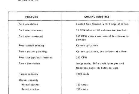
Characteristics and salient features for the UNIVAC 0603-04 Card Punch are listed in Table
2-1.
FEATURE
Card orientation
Card rate (minimum)
Card rate (maximum)
Read station sensing
Punch station punch ing
Read rate (optiona I feature)
Punch translation
Hoppe r capac ity
Stacker capacity
Norma I stacker
Reject stacker
CHARACTERISTICS
Loaded face forward, with 9 edge at bottom
75 CPM when all 80 columns are punched
200 CPM when a maximum of 14 columns is punched
Column by column
Column by column, two columns at a time
200 CPM
Image mode: 160 s ix-b it bytes per card
Compress mode: 80 bytes per card
1200 cards
750 cards
750 cards
Table 2-1. UNIVAC 0603-04 Cord Punch, Characteristics
3
UP-7772 UNIVAC CARD PUNCH SUBSYSTEM 9200/9200 11/9300/9300 11/9400
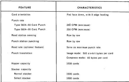
2.1.2. UNIVAC 0604-00 Card Punch
SECTION:
2
PAGE:
The UNIVAC 0604-00 Card Punch (row punch) is a freestanding, self-contained unit controlled by commands from the processor through a multiplexer channel (see Figure 2-3). This card punch feeds and punches 80-column cards, row by row, at a maximum rate of 200 CPM. When installed, optional feature F0945-00 increases the maximum punch rate from 200 to 250 CPM. Data to be punched is transferred from the multiplexer channel to an 80-bit punch buffer in the control unit which regulates the flow of data to and from the punch mechanism. Data received by the control unit is checked for validity then sent in either the image mode or the compress mode of translation to the punch mechanism. To ensure that the card is punched correctly, the control unit senses the data punched on the card and compares it with the data initially sent to the punch mechanism. The punched cards are then directed by program control into one of the two card stackers at the output.
When installed, Read/Punch Feature F0875-00 is a prepunch read unit that reads data from a prepunched card, row by row, into the control unit. Additional data can then be punched into the card when the command is received and transferred to the control unit for a comparison check.
Figure 2-3. UNIVAC 0604-00 or 0604-99 Card Punch
2.1.3. UNIVAC 0604-99 Card Punch
The UNIVAC 0604-99 Card Punch (row punch) is similar to the UNIVAC 0604-00 Card Punch (see Figure 2-3) except that the punch rate is 250 CPM. Characteristics and salient features for the UNIVAC 0604-00 or 0604-99 Card Punches (hereafter also referred to as UNIVAC 0604 Card Punch) are listed in Table 2-2.
UP-7772 UNIVAC 9200/9200 11/9300/9300 11/9400 2
CARD PUNCH SUBSYSTEM SECTION:
FEATURE
Card orientation
Punch rate
Type 0604-00 Card Punch
Type 0604-99 Card Punch
Read station sensing
Punch station punching
Read rate (optiona I feature)
Punch translation
Hopper capac ity
Stacker capacity
Normal stacker
Select stacker
CHARACTERISTICS
Fed face down, with 9 edge leading
200 CPM (maximum)
250 CPM (maximum)
Row by row
Row by row
Same as maximum punch rate
Image mode: 160 six-bit bytes per card
Compress mode: 80 bytes per card
1000 cards
1000 cards
1000 cards
Table 2-2. UNIVAC 0604 Card Punch, Characteristics
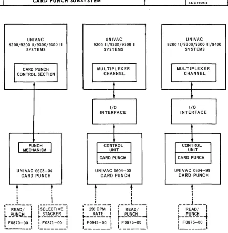
2.2. CONFIGURATION
PAGE:
The card punch subsystem consists of the UNIVAC 0603-04, 0604-00, or 0604-99 Card Punch. Figure 2-4 illustrates the functional arrangment of the subsystem components with the UNIVAC 9200/9200 11/9300/9300 11/9400 Systems. For the following card punch types there are two variations; they differ only in frequency of electrical supply:
• Card Punch, Type 0603-04 (60 hertz) or Type 0603-05 (50 hertz)
• Card Punch, Type 0604-00 (60 hertz) or Type 0604-01 (50 hertz)
• Card Punch, Type 0604-99 (60 hertz) or Type 0604-98 (50 hertz)
2.3. SUBSYSTEM COMPONENTS
The card punch subsystem components, described in the following paragraphs, consist of the UNIVAC 0603-04, 0604-00, and 0604-99 Card Punches.
2.3.1. UNIVAC 0603-04 Card Punch
The UNIVAC 0603-04 Card Punch (see Figure 2-1) is an 80-column serial-feed card punch. The subsystem component description of the serial punch is divided into two parts: the card punch mechanism 'and the processor punch control section.
UP-7772
UN IVAC 9200/9200 11/9300/9300 11/9400CARD PUNCH SUBSYSTEM
UNIVAC
9200/9200 11/9300/9300 II SYSTEMS
CARD PUNCH CONTROL SECTION
I
PUNCHI
MECHANISM
UNIVAC 0603-04 CARD PUNCH
t
I I•
•
,---.
I READ/ I
L
_P.Y~~H_~
: FOB70-00
I
!_---,
•
.
II
I
I
lSE~ECT~VE-!
I STACKER I
.. ---+
I
FOB71-00i
:- ______ 1UNIVAC 920011/9300/9300 II
SYSTEMS MUL TIPLEXER CHANNEL I/O INTERFACE CONTROL UNIT
CARD PUNCH
UNIVAC 0604-00 CARD PUNCH
+
~- ---~
I 2S0 CPM I
• RATE I
1---1
: F094S-00
I
, _ _ _ _ _ _ 1
t
I I I I•
,---.
i
READ/ :~_E.U!lS:.!:L-I
I I
I FOB7S-00 I
1
______ ,
NOTE: Dashed lines indicate optional features.
2
SE.CTION:
UNIVAC
9200 11/9300/9300 11/9400 SYSTEMS MUL TIPLEXER CHANNEL I/O INTERFACE CONTROL UNIT
CARD PUNCH
UNIVAC 0604-99 CARD PUNCH
,
I
I
,
a---.
: READ/
i
• PUNCH I1---;
i
FOB7S-00 :I I
,---,
Figure 2-4. Card Punch Subsystem Configurations
2.3.1.1. Card Punch Mechanism
Functional units of the serial punch mechanism are as follows:
• input station
• ready station
• read station (optional)
• wait-and-advance station
• punch station
• punch check unit
• output station
6
UP-7772 UNIVAC 9200/920011/9300/9300 11/9400
CARD PUNCH SUBSYSTEM
SECTION: 2
A description of each unit and its relationship to card flow follows. The card punch feed path is shown in Figure
2-5.
~
~u--
r
PUr...
PUNCH•
sr,qiio...
STATION~
~;:./ /;fr'~--- ,;;;,~.
~~r
STACKER~
PUNCHt
--:;~~tl!!?~~ "'o':~,"
...Tl
..
CHECK ... \
REJECT UNIT ... PICKERKNIFE
STACKER REAO':r ...
STATION
Figure 2-5. Card Feed Path for UNIVAC 0603-04 Card Punch
2.3.1.1.1. Input Station
PAGE:
The card hopper, which has a capacity of 1200 standard-thickness cards, and a pickerknife mechanism comprise the input station. Cards are loaded into the hopper face forward, with the 9 edge at the bottom (the broad-side feed method is used). The pickerknife mechanism feeds cards one at a time from the bottom of the card hopper into the first pair of feed rollers. The operation of the pickerknife mech-anism is controlled by a solenoid that is energized by the feed signal.
2.3.1.1.2. Ready Station
'rhe ready station holds one card. Application of a control (feed) signal to a pinch roller causes the card to move in a column-by-column manner into continuously running feed rolls, which transfer the card to the wait-and-advance station. The feed signal that is applied to the pinch roller is the same signal that is used to initiate the transfer of a card from the card hopper to the ready station. The ready station contains a photocell for controlling the time at which a card enters and leaves the ready station to be checked. This photocell functions as a jam detection sensor.
2.3.1.1.3. Read Station
The sensing unit and the sprocket drum are the major components of the read station .
• The sensing unit consists of an exciter lamp and 12 photodiode assemblies. As a card passes through the read station, the information punched in the card permits the light to pass through the holes and then activate the corresponding photodiodes. The signals generated by the photodiodes are applied to the pro-cessor punch control section.
• The sprocket drum, which is constantly rotating while the card punch mechanism is energized, provides timing signals for synchronizing data sensing and data transmission. The angular velocity of the drum is proportional to the linear velocity of the card traveling through the read station.
UP-7772 UNIVAC 9200/920011/9300/930011/9400
CARD PUNCH SUBSYSTEM
2.3.1.1.4. Wait-and-Advance Station
SECTION: 2
PAGE:
The wait-and-advance station controls the card for one cycle. The card is advanced from the wait-and-advance station through the punch station in two-column incre-ments by the card-pusher mechanism. The card-pusher mechanism consists of 41 spring-steel pusher blades attached to an oscillating platform. The wait-and-advance station contains two photocell diodes. The first photocell diode, which can be used as a jam detection sensor, is energized as the trailing edge of the card enters the ready station. In response to a signal from the first photocell diode, the processor punch control section provides a signal .to energize the card-brake solenoid. The second photocell diode is energized after the first advance operation to provide a timing signal for the first call for punch information. In response to the signal from the second photocell diode, the processor supplies the necessary punch-data signals, which represent the data to be punched in columns 1 and 2.
2.3.1.1.5. Punch Station
The information to be punched into a card is received from the processor in a column-serial fashion. The data received from the processor is translated into punched holes by 24 punch-actuator interposers that are mechanically interjected between the punch striker bar (which runs constantly) and the specified punch. The information is punched into the card in a column-by-column manner, two columns at a time. Punching accuracy is ±0.007 inch from the nominal hole loca-tion. A punch sprocket signal is supplied to the processor punch control section by the punch mechanism once per punch cycle to enable synchronization of the punch mechanism and the processor punch control section.
2.3.1.1.6. Punch Check Unit
The punch check unit, which provides the capability of sensing and verifying that all punches have physically penetrated the card, consists of 24 proximity trans-ducers. Each of these transducers generates an amplitude-modulated signal when the corresponding cutting punch penetrates the card. The output signals from these transducers are detected and interpreted by the processor punch control section. 2.3.1.1.7. Output Station
The postpunch area and two card stackers comprise the output station.
• The postpunch area is the area immediately following the punch station. Located in the postpunch area are a pinch roll and a photocell diode. A signal applied to the pinch roll from the processor punch control section causes the card to be ejected rapidly from the punch station. This signal may be applied to the pinch roll any time after the 14th column has been punched. The photocell diode is used as a jam detection sensor; also, the signal generated by this photocell diode indicates to the processor punch control section that the energizing signal applied to the pinch roll should be removed.
• Two card stackers are provided to receive cards exiting from the punch station; these are the normal stacker and the reject stacker. Each of these stackers has a capacity of 750 standard-thickness cards. A switch located at the bottom of the stacker assembly generates the appropriate control signal when either stacker becomes full. All cards that are punched correctly are routed to the normal out-put stacker; those punched incorrectly are routed to the reject stacker.
UP·7772 CARD PUNCH SUBSYSTEM UNIVAC 9200/9200 11/9300/9300 11/9400
2.3.1.2. Processor Punch Control Section
2
SECTION: PAGE:
The punch control section, which is a part of the general I/O structure of the pro-cessor, controls and monitors the operation of the serial punch mechanism. Comprising control logic and data paths, this section is designed to perform the following functions:
• to supply signals which prepare the punch mechanism for punch operations in one of two modes of translation;
• to synchronize the flow of data to and from the punch mechanism;
• to detect and interpret signals, both normal and abnormal, from the punch mechanism.
If the serial punch is conditioned for a punch operation and cards have advanced from station to station until a card is ready to enter the punch station (see Figure 2-5) on command from the processor, the processor punch control section initiates and controls operations in this sequence:
(1) Data is transferred in either the image mode. or the compress mode of translation from the processor main storage to the punch mechanism through data/ control paths of the processor punch control section. The transferred data is punched on a card fed from the wait-and-advance station. To ensure that the card is punched correctly, the processor punch control section receives and interprets signals from the punch check unit as the card is being punched.
(2) At the completion of the punch operation, the processor punch control section causes the punched card to be transferred to either the normal stacker or the reject stacker.
(3) If the read/punch feature (F0870-00) is installed and cards are to be read, a card is fed from the ready station through the read station to the wait-and-ad-vance station. As the card passes through the read station, data is read in either the image mode or the compress mode and applied to the processor punch control section, which transfers the data to the assigned processor memory storage area.
(4) The next card is fed from the hopper to the ready station, and the above process is repeated for each card in turn.
2.3.2. UNIVAC 0604 Card Punch
The UNIVAC 0604 Card Punch is an 80-column row-by-row card punch. The subsystem component description of the row punch is divided into two parts: the card punch mechanism and the control unit.
UP-7772 UNIVAC CARD PUNCH SUBSYSTEM 9200/9200 11/9300/9300 11/9400
2.3.2.1. Card Punch Mechanism
Functional units of the card punch mechanism are as follows: • input station
• wait station 1
• prepunch read station (optional) • wait station 2
• punch station
• postpunch read station • output station
2
SECTION:
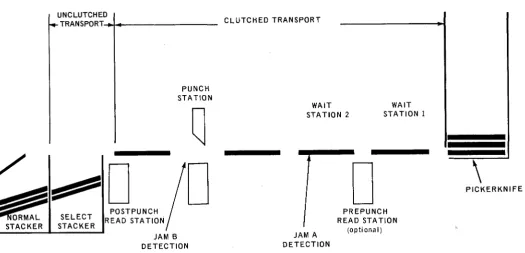
A description of each unit and its relationship to card flow follows. The card feed path is shown in Figure 2-6.
CARDS ARE ILLUSTRATED IN DECLUTCHED POSITION (348 DEGREES)
UNCLUTCHED
TRANSPORT~~---PUNCH STATION
CLUTCHED TRANSPORT
WAIT STA TlON 2
WAIT STATION 1
\
PAGE:
o
o
PICKERKNIFESELECT STACKER
POSTPUNCH READ STA TIOIIi
JAM B DETECTION
JAM A DETECTION
PREPUNCH READ STATION
(opti ona I)
Figure 2-6. Card Feed Path for UNIVAC 0604 Cord Punch
UP-7772 UNIVAC 9200/9200 11/9300/9300 11/9400
CARD PUNCH SUBSYSTEM
2.3.2.1.1. Input Station
2
SECTION:
The card hopper and the pickerknife mechanism constitute the input station. The hopper has a capacity of 1000 cards, which are stacked face down in a vertical column with the 9 edge leading. The pickerknife mechanism feeds one card at a time from the bottom of the card hopper into the first pair of feed rolls.
2.3.2.1.2. Wait Station 1
Wait station 1, which includes the first pair of feed rolls, holds the card for one cycle of the clutched transport system.
2.3.2.1.3. Prepunch Read Station
PAGE:
The prepunch read station provides row-by-row sensing of a card as it leaves wait station 1. Sensing is accomplished by means of flexible brushes which protrude through the punched holes of the card to make contact with the sensing roll. As each successive card row passes over the brushes, the control unit applies a probe pulse to the sensing roll. Where a hole is present in a particular row, the brush will protrude through the hole and make contact with the sensing roll. The same action takes place simultaneously for every hole detected in that particular row. An interlock switch prevents operation of the read/punch function if the brushes are incorrectly positioned.
2.3.2.1.4. Wait Station 2
In wait station 2, two functions are performed: The card is held for another cycle of the clutched transport system, and the position of the card in the card path is checked. Upon entering wait station 2, the leading edge of the card is sensed by a photocell diode, and the trailing edge is sensed as the card leaves wait station 2. This is known as A jam check. Any malfunction at this station lights the A JAM half of the MAN FEED A JAM/B JAM switch/indicator on the operator's
con-trol panel.
2.3.2.1.5. Punch Station
Data punched in a card at this station is received from the multiplexer channel and loaded into an 80-bit punch buffer. When the punch-activating mechanism is set to receive the new data, the punch buffer is unloaded and the data is translated into punched holes (row by row) by punch-activating interposers. These interposers are mechanically interjected between the punch drive bar (which runs constantly) and the specified punch. This process continues until all 12 rows of the card have been punched. As the card emerges from the punch station, it is checked by the B jam photocell diode at the leading and trailing edges of the card for position or card jam. Any malfunction at this station will light the B J AM half of the MAN FEED A J AM/B JAM switch/indicator on the operator's control panel.
UP-7772 UNIVAC
9200/9200 11/9300/9300 11/9400
CARD PUNCH SUBSYSTEM
2.3.2.1.6. Postpunch Read Station
2
SECTION:
In the postpunch read station, the same type of operation as was performed at the prepunch read station (see 2.3.2.1.3) is performed. The information sensed is loaded into an 80-bit read buffer where it is made available to the multiplexer channel. The read stations are located so that when one row of a card is being sensed at the postpunch read station, the sensing brushes of the prepunch read station are halfway between rows of another card. This half-cycle offset allows a single read buffer to be time shared between the stations.
2.3.2.1. 7. Output Station
The output station consists of two card stackers designated normal and select. Each has a capacity of 1000 standard cards. The output station is equipped with a card deflector which, when energized, intercepts and delivers a card to the select stacker. The normal stacker accepts all cards not delivered to the select stacker. When either stacker is filled to capacity, a switch located at the base of the stacker assembly shuts off the main drive.
2.3.2.2. Control Unit
The control unit which coordinates the operations within the row punch, comprises buffer storage, control logic, and data paths. The internal hardware is designed to perform the following functions:
• to receive commands from the processor and prepare the row punch for different modes of operation and for data handling;
PAGE:
• to synchronize the flow of data between the row punch and the multiplexer channel; and
'. to interpret signals, both normal and abnormal, from the row punch and to notify the processor of conditions within the unit.
If the row punch is conditioned for a punch operation and cards have advanced from station to station until a card is ready to enter the punch station (Figure 2-6), on command from the processor the control unit initiates a feed and punch signal. The command causes data to be transferred from an 80-bit punch buffer to the punch-activating mechanism. The data is punched in the card being fed from wait station 2. After each row is punched, it is read (sensed) and the information is stored in the read buffer. To verify that the data was punched into the card accurately, the sensed data is transferred to a postread hole counter for a hole count check. If the sensed data does not pass the hole count check, appropriate bits in the status byte and sense data byte will be set and card punch operations will stop (see 3.3.1.4 and 3.3.1.5).
At the normal completion of the punch operation, a command from the processor causes the control unit to direct the punched card into either the normal stacker or the select stacker.
If the read/punch feature (F0875-00) is installed and a read command is issued to the control unit from the processor, a card is fed from wait station 1 into the prepunch read station. As the card passes through the prepunch read station, each row of punched information is sensed and transferred to the read buffer for sub-sequent presentation to the multiplexer channel.
UP-7772 UNIVAC 9200/9200 11/9300/9300 11/9400
CARD PUNCH SUBSYSTEM
2.4. OPTIONAL FEATURES
2
SECTION:
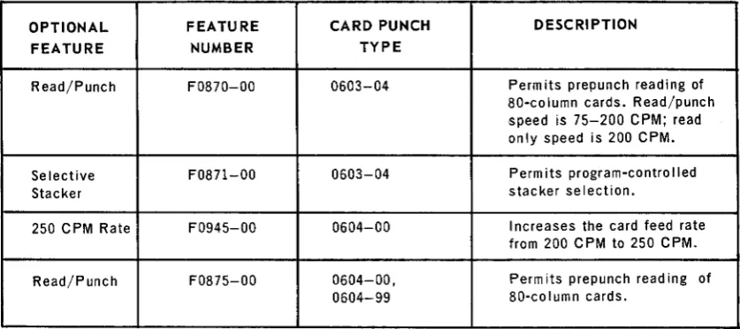
Optional features are available for each card punch type included in the card punch subsystem. Table 2-3 lists each optional feature, the feature number, the card punch type with which each feature is used, and a brief description of each feature.
OPTIONAL FEATURE CARD PUNCH DESCRIPTION
FEATURE NUMBER TYPE
Read/Punch FOS70-00 0603-04 Permits prepunch reading of
SO-column cards. Read/punch speed is 75-200 CPM; read only speed is 200 CPM.
Selective FOS7l-00 0603-04 Perm its program-contro lied
Stacker stacker selection.
250 CPM Rate F0945-00 0604-00 I ncreases the card feed rate
from 200 CPM to 2S0 CPM.
Read/Punch FOS7S-00 0604-00, Perm its prepunch read ing of
0604-99 SO-column cards.
Table 2-3. UNIVAC Card Punch Subsystem, Optional Features
2.5. INTERFACE BETWEEN PROCESSOR AND UNIVAC 0603-04 CARD PUNCH
The UNIVAC 0603-04 Card Punch, used with UNIVAC 9200/9200 11/9300/9300 II Systems, is under direct control of the processor punch control section. The interface between the processor and the serial punch mechanism is a data/control path which consists of a number of lines from the processor punch control section to the punch mechanism, and from the punch mechanism to the processor punch control section.
2.6. INTERFACE BETWEEN PROCESSOR AND UNIVAC 0604 CARD PUNCH
PAGE:
The interface between the processor and the UNIVAC 0604 Card Punch adapts the con-trol signals supplied by the multiplexer channel to the form required by the card punch. The following paragraphs describe the interface lines and the operation of the inter-face lines in the different sequences required for input/ output (I/O) instructions.
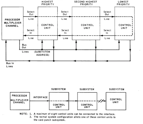
2.6.1. Interface
The I/O interface (F igure
2-7)
provides the means for time sharing communications between each processor multiplexer channel (UNIVAC 9200 11/9300/9300 11/9400Systems) and associated control units. The interface consists of four groups of lines: I/O busses, control lines, priority lines, and interlock lines.
When an operation is initiated, the multiplexer channel applies a signal to the select out line. The select out signal is sequentially applied to each control unit (passes serially through all control units) in order of priority.
UP-7772 UN IVAC 9200/9200 11/9300/9300 11/9400 CARD PUNCH SUBSYSTEM
Select Out
HIGHEST PRIORITY
Select Out
SECOND HIGHEST PRIORITY
Select Out
2
SE.C TION:
LOWEST PRIORITY
- - - -
- - - -
---1
Line Line Line
PROCESSOR I
I
MULTIPLEXER I
CHANNEL CONTROL CONTROL CONTROL I
UNIT UNIT UNIT
Select Select Select
Bus In Lines
Bus Out
Lines
PROCESSOR
MUL TIPLEXER CHANNEL
In
---Line
(SUBSYSTEM ADDRESS)
INTERFACE
In
---Line
SUBSYSTEM SUBSYSTEM
---
-CONTROL CONTROL
UNIT UNIT
~
In
-Line
SUBSYSTEM
CONTROL UNIT
NOTE: 1. A maximum of eight control units can be connected to the interface. 2. The normal system configuration allots one of these control units to
the card punch subsystem.
Figure 2-7. Interface to Multiplexer Channel (Part 1 of 2)
I
I
I
I
14
UP-7772 UNIVAC 9200/920011/9300/9300 11(9400
CARD PUNCH SUBSYSTEM
BUS OUT
Bit Pos ition 7 6 5 4
3
2
1
0
Parity (P)
CONTROL OUT Address Out Function Out Service Out
PRIORITY OUT
Select Out
UNIVAC Suppress Out
9200 II/ Hold Out
9300/9300 II/ INTERLOCK OUT
9400 SYSTEMS
MUL TIPLEXER Operational Out
CHANNEL
BUS IN
Bit Position 7
6 5 4
3
2
1
0
Parity (P)
CONTROL IN
Address In Status In Service In
PRIORITY IN Request In Select In
INTERLOCK IN Operationa I In
CONTROL UNIT(S)
Figure 2-7. Interface to Multiplexer Channel (Port 2 of 2)
2
15
UP-7772 UN IVAC 9200/9200 11/9300/9300 11/9400
CARD PUNCH SUBSYSTEM SECTION:
2
The select out signal is applied to the subsystem with the highest priority. If the address is not that of the addressed unit or the unit does not require service, the select out signal is applied to the subsystem with the next highest priority. This
operation continues until the select out signal is applied to the addressed or requesting subsystem. If none of the control units recognizes the address or requires servicing, the lowest priority control unit sends the select in signal to the multiplexer channel.
PAGE:
When a subsystem accepts the address or is the requesting unit, it captures the interface by applying a signal to the operational in line and thereby inhibits passage of the select out signal to the next lower priority subsystem. Normally, the subsystem retains control of the interface for a short interval (execution of immediate commands or transfer of a single byte of data) and relinquishes control by passing the select out signal to the next lower priority unit. During the next initiation of the select out signal, the operation is repeated; thus, another data byte is transferred. This process is repeated until the transfer operation is complete and the channel is notified of this status.
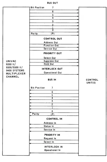
2.6.1.1. Bus Lines
The bus out lines carry addresses, commands, and data from the multiplexer channel to the subsystem control units. The bus in lines carry addresses, data, status, and sense information from a subsystem control unit to the multiplexer channel. The type of information contained on the bus out and bus in lines is identified by a simultaneous signal on the appropriate control line. (See Figure
2-7.)
The bus lines consist of nine bus in and nine bus out lines (each group consists of eight data lines and one parity line). Except for control signals, all data trans-mitted between the processor and subsystems is carried on these lines. Any signal provided by the processor multiplexer channel is common to all control units. However, only one control unit at a time can be logically connected to the multi-plexer channel.
Bit position 7 on a bus is designated the low-order value of a byte, and bit position
o
is designated the high-order value, with intervening bits in descending order. When it is necessary to transmit less than eight data bits, the bits must be located in the highest number adjoining bit positions of the bus. All unused lines must be the low numbered lines (bit position 0 and adjoining bit positions). The parity bit must always be the result of odd parity.2.6.1.2. Control, Priority, and Interlock Lines
When these lines are active, they identify the data on the bus lines and in some cases permit an operation to be performed. The signal name, the origin of the
signal, its purpose, and the effect of each control and priority line and the interlock line are given in Table
2-4.
UP-7772
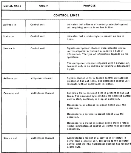
CARD PUNCH SU BSYST EM UNIVAC 9200/9200 11/9300/9300 11/9400SIGNAL NAME ORIGIN
2
SECTION:PURPOSE
CONTROL LINES
Address in Control unit Indicates that address of currently selected control unit requiring service is on bus in line.
Status in Control unit indicates that a status byte is present on bus in lines.
Service in Control unit Signals multiplexer channel when selected control
unit is prepared to transmit or receive a byte of information. The type of information depends on the operation.
The multiplexer channel responds with a service out, command out, or an address out (during a disconnect) signal.
Address out Miliplexer channel Signals control units to decode control unit address present on bus out I ines. The addressed control unit responds with an operational in signal.
Command out Mu Itiplexer channel Indicates that a command byte is present on bus out lines. The command byte notifies the selected control unit to start, continue, or stop an operation.
Response to an address in signal means start the operation.
Response to a service in signal means stop the operation.
Response to a status in signal means stack ( retain status information at control unit until next selection sequence).
Service out Multiplexer channel Acknowledges receipt of a service in or status in signal from a control unit. Indicates to the selected control unit that the multiplexer channel has received a data byte.
Table 2-4. Control, Priority, and Interlock Lines Between the Processor and the UNIVAC 0604 Card Punch (Part 1 of 2)
17
UP-7772 UNIVAC 9200/920011/9300/930011/9400 CARD PUNCH SUBSYSTEM 2
SECTION:
SIGNAL NAME ORIGIN PURPOSE
PRIORITY LINES
Request in Control unit Indicates that control unit is prepared to transmit status or data, and requests a selection sequence.
Se lect out Multiplexer channel Establishes communications with control unit whose address is on bus in lines.
Select in Control unit Indicates address byte is not recognized by any
control unit (completes path of select out signal).
Suppress out Multiplexer channel Informs control units not to generate service requests in an attempt to seize the interface. This signal suppresses any subsequent data or status transfer.
Hold out Multiplexer channel Indicates that select out signal will begin. This signal is present only for the time the select out signal is present and terminates when a control unit seizes the interface.
INTERLOCK LINES
Operational in Control unit Ind icates that a control unit has been selected and is to be present for the entire period of time that data is being transmitted to the multiplexer channel.
Operationa lout Multiplexer channel Allows operations between control units and multi· plexer channel. When this signal is not present, all lines to the channel are rendered inoperable.
Table 2-4. Control, Priority, and Interlock Lines Between the Processor and the UNIVAC 0604 Card Punch (Part 2 of 2)
18
UP-7772 UNIVAC 9200/9200 11/9300/9300 11/9400
CARD PUNCH SUBSYSTEM
2.6.2. Operation of Interface
SECTION:
2
PAGE:
The multiplexer channel, by means of the interface, controls the transfer of command, data, sense, and status information. The interface accomplishes the transfers by permitting the operational sequences listed here. These operational sequences are also illustrated in Figure 2-8:
• Initial section • Control unit request • Status transfer • Data transfer • Control unit busy
2.6.2.1. Initial Selection Sequence
An initial section sequence is started when the multiplexer channel addresses a control unit during the execution of a start-I/O instruction (see Figure 2-8).
The format for the address portion of the start-I/O instruction is shown in Figure
2-9.
T
INITIAL SELECTION SEQUENCE (ISS)
START I/O INSTRUCTION SELECTS CONTROL UNIT
AND DEVICE
IS CONTROL UNIT BUSV
No
CONTROL UNIT SENDS ADDRESS TO CHANNEL
CHANNEL SENDS COMMAND TO DEVICE
Ves
No
Ves
CONTROL UNIT INITIATES CONTROL UNIT BUSV SEQUENCE TO TRANSFER BUSV STATUS TO CHANNEL
CONTROL UNIT DISREGARDS COMMAND AND INITIATES
':> • I STATUS TRANSFER SEQUENCE
CONTROL UNIT ACCEPTS COMMAND
TO TRANSFER END STATUS BVTE
CONTROL UNIT INITIATES STATUS TRANSFER SEQUENCE TO TRANSFER
INITIAL STATUS BVTE
CONTROL UNIT INITIATES CONTROL UNIT REQUEST
SEQUENCE
CURS
STS
CONTROL UNIT REQUEST SEQUENCE (CURS)
FROM INITIAL
SELECTION SEQUENCE ( •
+
Ve.
CONTROL UNIT ALERTS CHANNEL OF COMMUNICATIONS
REQUEST (REQUEST IN)
CHANNEL RESPONDS WITH SELECT OUT SIGNAL
CONTROL UNIT BLOCKS POLL, CAPTURES INTERFACE,
AND SENDS DEVICE ADDRESS TO CHANNEL
CHANNEL NOTIFIES CONTROL UNIT TO PROCEED
WITH DATA OR STATUS TRANSFER
No
BUFFER CONTROL WORD IS UPDATED
CONTROL UNIT INITIATES STATUS TRANSFER SEQUENCE TO TRANSFER
STATUS BVTE
CONTROL UNIT INITIATES DATA TRANSFER SEQUENCE TO TRANSFER
DATA BVTE
DTS
Figure 2.-.8. Type 0604 Card Punch Contra I Unit Operational Sequences (Part 1 of 2)
(
( j
(
)
o
~ I ...;J ...;J ...;J Nnc
>Z
;0<
a~ -00 c:~zg
n:a
:::J:'" o
(
(
(
STATUS TRANSFER SEQUENCE (STS) DATA TRANSFER SEQUENCE (DTS)
CONTROL UNIT BUSY SEQUENCE (CUBS)
FROM "
-8
STSINITIAL
SELECTION / SEQUENCE /
IS SUPPRESS SIGNAL OUT UP
No CONTROL UNIT
SENDS STATUS BVTE TO CHANNEL
CHANNEL RESPONDS WITH SERVICE OUT
OR COMMAND OUT SIGNAL
010 CHANNEL RESPOND WITH SERVICE OUT
Yes·
CHANNEL ACKNOWLEDGES RECEIPT OF STATUS. CON-TROL UNIT WILL CLEAR
STATUS IN AND STATUS IN PENDING
WAS THIS AN END STATUS BVTE
Ve.
END OF OPERATION
Ves
No ....
RELEASE POLL SIGNAL TO NEXT CONTROL UNIT
COMMANO OUT CAUSES CONTROL UNIT TO REMAIN IN PENDING STATE WITH STATUS BVTE STACKED
FROM
"""F
CONTROL • ) UNIT REQUESTCONTROL UNIT TRANSMITS OR RECEIVES ONE
BVTE OF DATA
SEQUENCE
Ve.
TERMINATE DATA TRANSFER
TERMINATE DATA TRANSFER
TERMINATE DATA TRANSFER
CONTROL UNIT INITIATES STATUS TRANSFER SEQUENCE TO TRANSFER
END STATUS BVTE
.SERVICe- OUT indicates channel accepted status byte.
"COMMAND OUT indicates data on Bus In lines not valid. Control Unit must stack status.
Figure 2-8. Type 0604 Card Punch Control Unit Operational Sequences (Part 2 of 2)
SEND STATUS CONTAINING MODIFIER BIT AND BUSV BiT TO
CHANNEL
c::
'tl•
'-l '-l '-l IVnc:
~~:::a
<o~ n "'tJ", C:'"
zg
n~ %~CIt 0
c:-",,,-CIt'"
-<l::
CIt 0
UP-7772
UN IVAC 9200/9200 11/9300/9300 11/9400CARD PUNCH SUBSYSTEM
BIT POSITION 0 1 2 3 4 5 6
ADDRESS T S S S U U U
7 8
U P
Figure 2-9. Address Format
SE.CTION:
Parity
Device Address
o
indicates nonshared subchannel2
Prior to performing the incoming command, the control unit checks for the follow ing conditions:
• invalid address
• control unit busy
• command parity incorrect
• stored status
If any of these conditions are present, the control unit rejects the command and
sends an appropriate status byte to the multiplexer channel (see 3.3.1.4).
For a start-I/O instruction, the control unit initiates the following:
• status transfer sequence to indicate equipment status at the initiation of a specific command (initial status byte);
• control unit request sequence (see 2.6.2.2);
• status transfer sequence at end of the initial section sequence to indicate acceptance of command (end status byte).
Execution of a sense or read command means that two status bytes (initial status
PAGE:
byte and end status byte) must be generated. When the multiplexer channel indicates that the initial status byte is processed, the control unit then executes the command. At the conclusion of the command, another status transfer sequence is initiated. The end status byte and a device end bit are sent to the multiplexer channel indicating
equipment status if the command has been successfully completed. When tile
status byte is accepted by the multiplexer channel, the status-in-pending state is
cleared and the status register is cleared to binary O. The control unit is
UP-7772 UN IVAC 9200/9200 11/9300/9300 11/9400
CARD PUNCH SUBSYSTEM
2.6.2.2. Control Unit Request Sequence
2
SECTION:
The control unit request sequence is initiated when the control unit is required to communicate with the multiplexer channel and is disconnected from the interface. For read, sense, or end status byte operations, the control unit sends the request in signal to the multiplexer channel, and the channel responds only if the external interrupts are not locked out. The control unit captures the interface with the operational in signal and identifies the control unit requesting attention. The multiplexer channel responds with the command out signal, the buffer control word is decremented, and the control unit then proceeds to perform a data transfer to status transfer sequence as required.
2.6.2.3. Data Transfer Sequence
A data transfer sequence (to or from channel) is normally initiated at the con-clusion of a control unit request sequence for operations which require the transfer of data or sense data bytes.
PAGE:
For an input operation (control unit to multiplexer channel), the multiplexer channel initiates either a service out or command out signal. The service out (proceed) signal causes the control unit to transmit another data byte during the next data transfer sequence. The command out (stop) signal is generated by the multiplexer channel when the buffer control word is decremented to O. The control unit then proceeds to initiate a status transfer sequence.
An output operation (processor to control unit) is similar to an input operation except the control unit samples the output data byte on the bus out lines during the time the service out signal is present. The data transfers terminate when the command out signal, in response to the service in signal, is received at the control unit.
During the data transfer sequence, any of the abnormal conditions listed here can be detected in the addressed tape unit .
• Data Late
If the multiplexer channel does not respond with a service out or command out
signal within a specific time frame, the current operation is aborted. The end status byte contains a 1 bit in the unit check bit position (bit 6), and a sense data byte (in response to a sense command) is transmitted to the multiplexer channel (with appropriate bit set) to indicate a data late condition (see 3.3.3) .
• Parity Error
If a parity error is detected on the bus out lines, the current operation'"is aborted. The end status byte contains a 1 bit in the unit check bit position (bit 6), and a sense data byte 1 (in response to a sense command) is transmitted to the multiplexer channel (with appropriate bit set) to indicate a parity error condition (see 3.3.3).
UNIVAC 9200/9200 11/9300/9300 11/9400
CARD PUNCH SUBSYSTEM
2.6.2.4.
Status Transfer Sequence2
SECTION:
Depending on conditions, the status transfer sequence causes the control unit to send either the initial status or end status byte (see 3.3.2) to the multiplexer channel in such a way that:
• The
initial
status byte is sent to the multiplexer channel during -this sequence after successful initiation of the current operation •• The end status byte is generated during this sequence to indicate completion of current operation.
2.6.2.5.
Control Unit Busy SequenceThe control unit busy sequence is entered from an initial selection sequence if
at time of selection the control unit is executing a previously initiated operation or contains a status byte for a tape unit being addressed. A status byte contain-ing a 1 bit in the status modifier and busy bit positions is transmitted to the multiplexer channel.
2.6.2.6.
System Reset OperationThis operation is performed when the SYSTEM RESET switch on the console is pressed. This switch is pressed:
(1) when power is initially turned on;
(2) when the multiplexer channel has been disconnected from the interface; and (3) as part of the initial program-loading procedure.
A system reset operation is indicated at the interface:
(1) by the concurrent absence of the operational out and suppress out signals (see Table
2-4);
and(2) when the control unit is in the online mode.
This condition causes the operational in signal to be absent and the control unit and its status to be reset. The control units will be in a busy status for the duration of the reset procedure.
2.6.2.7.
Selective Reset OperationThis operation terminates data transfers and resets the selected control unit when a malfunction is detected at the multiplexer channel.
PAGE:
A selective reset operation is indicated at the interface by the presence of the select out signal and by the absence of the operational out signal (see Table
2-4).
This condition causes the operational in signal to be absent and the operating control unit and its status to be reset.
UP-7772 UNIVAC 9200/9200 11/9300/9300 11/9400
CARD PUNCH SUBSYSTEM
1'.6.2.8. Interface Disconnect
2
SECTION:
In this operation, the selected control unit completes its current operation and re leases the interface.
An interface disconnect operation is indicated at the interface by the presence of the address out signal and by the absence of the select out signal prior to completion of any signal sequence.
When the control unit is disconnected from the interface, it responds by removing
all signals (with the exception of request in) from the interface. If the control
unit was effecting an input operation at time of disconnect, the data on bus in
lines need not be valid. If the disconnect occurred during an output operation,
the data on the bus out lines must be valid until the absence of the service in or operational in signal. When the control unit reaches the normal ending point it attempts to obtain selection on the interface to present any generated status to the multiplexer channel.
If the interface disconnect occurred prior to the acceptance of the initial status
or after the acceptance of the device end status byte for an operation by the multiplexer channel, the control unit does not generate a status byte as a result of the interface disconnect.
25
UP-7772 UNIVAC CARD PUNCH SUBSYSTEM 9200/9200 11/9300/9300 11/9400
SECTION:
3
PAGE:
3. PROGRAMMING
3.1. GENERAL
This section of the manual provides information concerning input/output (I/O) control of the UNIVAC 0603-04 Card Punch (which is an integral part of the UNIVAC 9200/
9200 11/9300/9300 II Systems) and of the UNIVAC 0604 Card Punch (which is used with
the UNIVAC 9200 II/9300/9300 11/9400 Systems by way of a multiplexer channel).
3.2. UNIVAC 0603-04 CARD PUNCH I/O OPERA TION
The UNIVAC 0603-04 Card Punch responds to commands specified by bits 27 through
31 of the execute-I/O (XIOF) instruction (UN IVAC 9200/9200 II/9300/9300 II Systems).
EXECUTE-I/O (XIOF) INSTRUCTION
0
OP CODE 12 FIELD
HEXADECIMAL
DEVICE ADDRESS REPRESENTATION
7 8 15
BASE REGISTER
NOT USED
16 19
DISPLACEMENT
---~---
,-NOT USED COMMAND BYTI;
20 23 24 31
Figure 3-1 shows the functional relationship between the processor and the serial punch when a command is to be executed. When the concurrent operating system (COS) or the nonconcurrent operating system (NCOS) is in use, the execution of commands for the serial punch occurs only when the processor is in the input/output program state.
UP-7772
o
UN IVAC 9200/9200 11/9300/9300 11/9400
CARD PUNCH SUBSYSTEM
-I
LOW ORDER MEMORYI
BU F FER CON TR 0 L WO f}.t.J.tD<---.L..-_ _ -. II
SECTION:
I
I
COLUMNS BASE I ADDRESS3
I
0I
7 8 15 16 23 : 24 31
I
-XIOF DEVICE
ADDRESS
78 15 16
0 - - - 0
PROCESSOR
PUNCH ~
CONTROL
23 24
COMMAND CODE
31
~0®
~~
--
USER DATA--PUNCH MECHANISM
I---~---
1 - -1--I
II
o
PROCESSOR PROGRAM STATE CONTROL 3LOW ORDER MEMORY
CC
~
OR
0 0
IN PUT jOUTPUT
PROGRAM S A
STATE CONTROL
16 19
66 67
- - -
---.-1----NOTES:
(1) Circled numbers refer to step numbers in 3.2.
(2) CC
=
condition code OS = device status DA = device address--000
-=r
I I
I MAIN I
I
I STORAGE I
,-_ _ _ _ _ _ 1
Figure 3-1. Command Function Relationship Between UNIVAC 9200/9200 11/9300/9300 1/ Systems and UNIVAC 0603-04 Card Punch
2
UP-7772
0
UNIVAC 9200/9200 11/9300/9300 11/9400
CARD PUNCH SUBSYSTEM SECTION:
3
PAGE:
When the minimum operating system (MOS) is in use, all commands for the serial punch are executed in the processor program state. A knowledge of the UNIVAC 9200/9200 11/ 9300/9300 II Systems Card Assembler Programmers Reference, UP-4092 (current version) is necessary when using the .information that follows.
Listed below are the initial steps required to execute a command for the UNIVAC 0603-04
Card Punch by use of the UNIVAC 9200/9200 11/9300/9300 II Systems.
(1) Load the proper buffer control word. (For reading, load locations 72, 73, 74, and 75;
for punching, load locations 76, 77, 78, and 79.
The buffer control word for the card punch contains:
:
1
HTS COL BASE I ADDRESS
I
7 8 15 16 23124 1 31
where: HTS = Hardware temporary storage reserved for the reader. This byte should not be loaded by the program. COL = The number of columns to be read or to be punched.
For reading, this number must always be 80; for
punching, any even nonzero number less than 81 may be be specified. At the end of a card operation, this
count is decremented to zero.
BASE ADDRESS = The address of the most significant half-word (even-numbered address) of the card read area in memory. Upon completion of the operation, this address is one greater than the address of the last byte into which information was read, or this address will point to the byte immediately following the last byte of information punched.
(2) Load the device address into bit positions 8 through 15 of the XIOF instruction. (3) Load the command byte into bit positions 24 through 31 of the XIOF instruction.
If the MOS is used, all interrupts must be inhibited (bit 27 must be a 1).
If the COS or NCOS is used, interrupts must not be inhibited (bit 27 is iii 0).
UP-7772
0
UNIVAC 9200/920011/9300/930011/9400
CARD PUNCH SUBSYSTEM
(4) Issue XIOF instruction.
OP CODE
3
SECTION:
01 FIELD
DEVICE ADDRESS 81 FIELD
-
...--i
I
A:4 00000010 0000 0000 OOOH SXRP
I I
:
7 8 15 16 19 20 23 24 27 28where: H = 1 Inhibit all interrupts (for dedicated I/O device).
P = 1 Punch a card.
R
=
1
Read a card.x
= 0 Read and/or punch a card in compressed mode (see3.3.1.5.2).
X =
1
Read and/or punch a card in image mode (see3.3.1.5.1).
S = 1 Select stacker. Effective only if the program stacker select feature is installed. Otherwise, this specification is ignored.
Either the R or P bit must be 1 (both cannot be 0). All other bits shown as O's must be O's, or an error may result.
Feeding with no reading or punching is done by specifying the punching of two blank columns.
The second punch stacker is an error stacker and is selected on punch errors. This stacker is program selectable. However, errors will cause this stacker to be selected regardless of program choice. Stacker selection is given for the
31
PAGE:
card in the punch wait station in the same instruction that causes it to be punched.
(5) Check the condition code (CC) setting to determine if the instruction was accepted.
CC
00 = command accepted
10
=
busy11
=
command rejected - invalid device address or device offline(6) Store and test the status of the serial punch after the operation is completed to determine if the operation was successful.
UP-7772
LABEL I
I
I
I
I
J
I
J
I
e OH I I
I
I
UNIVAC 9200/9200 11/9300/9300 11/9400
CARD PUNCH SUBSYSTEM
Examples of the statements of steps (1) through (6) are:
, OPERATION' OPERAND
,
COMMENTS10 16
... I\I,e e (. W+ I (,} ) CIO .. LOAO IA,CW ASSI(;MliD TO ,S,E R IIA ..
3
SE.CTIQN:
PUHC-II I
Mill 1 ,~,+ I ,I~ , 0,2' I IL 0 A 0 lOt" I CI~ AD 0111 e~! ,N,T,O, 11I,I,O,F, II,H,t,T,RIU,C,T,' ,OIH MI\lt ~ +,1 l \ ' 0 6 ' I IL OA 0 Ie OM"'''I'' 0 e 'I'IT f. I HIT 0 ,1110 F I HIS, T
,,1/
C-IT 10M I III 0 F X·02.'1 " ' 0 6 1 ' IP U H C. ~I A Il AIR 0 I HI I '" ",<rIf .. 0011 I I Ialc
.,
, . liT _1 It,F, C. Ilj: 0 &"IA H (_ell JT 0 e III T 1 I ~ J10 1/ 00 t ".1',) 'W \ 02. ' C c ,:1/,0,0 ", 5o,T, O,RIE STATvs I
I" I ~ ,) I I I ~
I" I I I ~,~OO IJMG- foR T E SIT I ... Go IS TAT "is I I I
I" I J
J.
I I I II" I I I I I I I I I I I
DC X • SO 01600 ' I I I I I I I , I , I I I I I
,
, , I ,,
I I I I 1 1 I II I I I 1 I J I J I ~
I I I I ~ I ~ I ~ I
I J I ~ I I I
5
UP-7772 UN IVAC 9200/9200 11/9300/9300 11/9400
CARD PUNCH SUBSYSTEM
SECTION: 3
When COS or NCOS is in use, the supervisor request call (SRC) instructs the super-visor to execute the instructions shown in the above example in the input/output program state.
(7) In case of an error, display the status byte and instruct operator to take appro-priate action according to error recovery message. A status byte is stored in location 66 (DS) of low order main storage and contains information pertaining to the result of the last issued order or to the next-to-Iast issued order. The bits which comprise the status byte [He designated in Figure
3-2
and described in Table 3-1.PAGE:
DATA
t
PARITY ERRORCONTROL \
PUNCH CHECK ERROR
NOT USED
PHOTOCELL CHECK ERROR
INTERRUPT PENDING
HOPPER EMPTY
STACKER JAM, INTERLOCK, PUNCH ENTRY OR EXIT CHECK
OR STACKER FULL
NOT USED
Figure 3-2. UNIVAC 0603-04 Card Punch, Status Byte Format
If the status byte contains all O's, the function is performed as specified.
UP-7772
BIT
UNIVAC 9200/9200 11/9300/9300 11/9400
CARD PUNCH SUBSYSTEM
BIT
3 SECTION:
POSITION DESIGNATION DEFINITION
0 Stacker jam, inter- Set to indicate stacker jam, interlock broken, punch entry, lock, punCh entry, or exit check, or any other c