SunDiagnostic Executive User's Guide
For MC68020, MC68030, and SF9010IU
(SPARC) Based Sytems
SunDiagnostic Executive User's Guide
ForMC68020,MC68030,and
SF9010IU (SPARC) Based Systems
Sun Microsystems, Inc. • 2550 Garcia Avenue • Mountain View, CA 94043 • 415-960-1300
The Sun logo, Sun Microsystems, and Sun Workstation are registered trademarks of Sun Microsystems, Inc.
Sun, Sun-2, Sun-3, Sun-4, Sun386i, Sunlnstall, SunOS, Sun View, NFS, NeWS, and SP ARC are trademarks of Sun Microsystems, Inc.
UNIX ~s a registered trademark of AT&T.
All other products or services mentioned in this document are identified by the trademarks or service marks of their respective companies or organizations.
ALM and ALM2 arc trademarks of Sun Microsystems, Inc. I SunIPC is a trademark of Sun Microsystems, Incorporated. Multibus is a trademark of Intel Corporation.
Tapemaster is a trademark of Ciprico, Inc.
Copyright© 1989 Sun Microsystems, Inc. -Printed in U.S.A.
All rights reserved .. No part of this work covered by copyright hereon may be reproduced in any form or by any means - graphic, electronic, or mechanical -:-including photocopying, recording, taping, or storage in an infonnation retrieval system, without the prior written pennission of the copyright owner.
Restricted rights legend: use, duplication, or disclosure by the U.S. government is subject to restrictions set fo1th in subparagraph (c)(l)(ii) of the Rights in Technical Data and Computer Software clause at DFARS 52.227-7013 and in similar clauses in the FAR and NASA FAR Supplement.
Contents
Chapter 1 Introduction ...
3
1.1. Audience... 3
1.2. Common Terms ... 3
1.3. Conventions ... 3
Fonts... 3
Hexadecimal Values ... 4
1.4. References ... 4
1.5. The Exec Tape ... 4
1.6. Organization of This Manual ... 4
1.7. Required Equipment... 5
1.8. Software Requirements ... 5
Configuring a Terminal ... ... 5
Chapter 2 Using the SunDiagnostic Executive ...
9
2.1. What This Chapter Contains ... 9
2.2. History ... 9
2.3. Overview ... '.:•:••:•:•:•:o.o.•~· ... . 2.4. The Exec Tape ... .-;,;;;;._.;;;:+•, ... ;,:..+.'.··· 2.5. Loading and Booting the Exec ... +;;; ••• ;·;:;:;,~• ... :-. •.• ;·;:;:;:.;:;:;· .... ;<< Halting the System ... ·'."''':;:;·:,.,.;• . .,,. ... .,:•~,. .. '..;.;,;,,:•:•:•·•• .. .-:·~·••···~·~'''<< Installing the Exec Onto Disk ... .;+••:,:•··.'.·i~•;:••·'.~·-.•o.'•"·.•·:~~·"··"~:•:•:•:•:•:••·~· .. ::::::::"·
Servers vs Local Disk ... ,;;,;;·;,;·;·.•+·~·'"''''°''."'.;••••;•.;•;••:•:'· .. •'.:::::::::
Booting from Disk ... , .... ;;:;,;,;,;,;,,,, ... _.,, .... , ... . Booting from Tape ... , •.•• :~~·'~·'·'-'·· ... ..
-iii-Contents - Continued
2.6. The Exec Environment ... 22
The Menu Perspective ... 22
The Operating System Perspective ... 23
2. 7. User lnterf ace ... 25
Menu Structure ... 25
Global Options ... 26
Command Line Syntax... 27
Command Parameters ... 27
Special Characters ... 28
2.8. Exec Menus ... 29
The Main Menu ... 29
The Environment Menu ... 30
The Options Menu ... 35
Diagnostics Menu ... 36
Starting A Diagnostic ... ... 39
Status Menu ... 39
Log Menu... 40
2.9. Writing Script Files ... 41
2.10. Remote Execution and the Network Console ... 42
Chapter 3 Sun-3/400 Series Central Cache Diagnostic ... 47
3.1. General Description ... 47
3.2. What This Chapter Contains... 47
3.3. Overview of the Diagnostic ... 47
3.4. Hardware Requirements ... 47
3.5. Firmware Requirements ... 48
3.6. Additional Requirements ... 48
3.7. User Interface ... 48
3.8. Starting the Diagnostic ... 48
3.9. The Diagnostic Menus... 48
Main Menu ... 49
Command Parameters ... 49
Environmental Parameters ... 51
-iv-Contents - Continued
All Tests in Sequence ... 52
Default Test Sequence ... 52
Quick Test Sequence ... 52
Level 1 Menu ... 52
Level 2 Menu ... 55
Cross Boundary Menu ... 57
Blockcopy Menu... 59
Options Menu ... 60
Display Error Log ... 63
3.10. Messages... 64
3.11. Glossary... 64
Chapter 4 SPARCsystem 330 Cache Diagnostic... 69
4.1. General Description ... 69
4.2. What This Chapter Contains ... 69
4.3. Overview of the Diagnostic ... 69
4.4. Hardware Requirements ... 70
4.5. User Interface... 70
4.6. Starting the Diagnostic ... 70
4.7. The Diagnostic Menus... 70
Main Menu ... 71
Parameters ... ... ... ... ... 71
Data RAM Test Menu ... 71
Tag RAM Test Menu ... 72
Read Menu ... 72
Write Menu ... 72
Flush Menu ... 72
Debug Menu ... 72
Execute Quick Test Sequence ... 72
Execute Default Test Sequence ... 72
Execute All Tests ... ... 72
Set Environmental Variables ... 72
Display Error Log ... 72
-v-Contents - Continued
Clear Error Log ... 73
Data RAM Test Menu ... 73
Data RAM Write/Write Next Pattern Test ... 73
Data RAM Address Test ... 73
Data RAM 3-Pattem Test ... 74
Data RAM Walking Ones Test... 74
Data RAM March Test ... 74
Execute All Cache Data Tests... 74
Tag RAM Test Menu ... 74
Read Menu ... 75
Read Hit Test ... 75
Read Hit Context Test ... 76
Read Hit Supervisor Access Violation Test ... 76
Read Hit/Write Hit (Load Store) Test ... 77
Read Miss Test ... 77
Read Miss Alignment Test ... 78
Read Miss Valid Bit Set Test ... 78
Read Miss/Write Hit (Load Store) Test... 79
Read Miss Tag Update Test ... 79
Execute All Cache Read Tests... 79
Write Menu ... 80
Write Hit Test ... 80
Write Hit, Write Protection Violation Test ... 81
Write Hit, Alignment Test ... 81
Write Hit, Modified Bit Test... 82
Write Miss Test ... 82
Write Miss, Valid Bit Test ... 83
Load Store, Write Protection Violation Test ... 83
Write Exerciser Test ... 84
Execute All Cache Write Tests ... 85
Flush Menu ... 85
Cache Context Flush Test ... 85
Cache Segment Flush Test ... 86
-vi-Contents - Continued
Cache Page Hush Test ... 86
Execute All Cache Hush Tests... 87
Debug Menu ... 87
Tag RAM Write ... 88
Data RAM Write ... 88
Tag RAM Read ... 88
Data RAM Read ... 89
Tag RAM Write/Read ... 89
Data RAM Write/Read ... 89
4.8. Error Messages ... 90
Main Menu Error Messages ... 90
Data RAM Test Menu Error Messages ... 90
Tag RAM Test Menu Error Messages ... 90
Read Menu Error Messages ... 91
Write Menu Error Messages... 93
Flush Menu Error Messages ... 95
4.9. Glossary ... 96
Chapter 5 1/0 Cache Diagnostic ... 99
5 .1. General Description ... 99
5 .2. What This Chapter Contains ... 99
5.3. Overview of the Diagnostic ... 99
5.4. Hardware Requirements ... 99
5.5. Firmware Requirements... 100
5.6. User Interface ... 100
5. 7. Starting the Diagnostic ... ... 100
5.8. The Diagnostic Menus... 100
Main Menu ... 100
Optional Parameters ... 101
Tag RAM Memory Tests Menu ... 101
Data RAM Memory Tests Menu ... 102
Noncached Hits/Misses Tests Menu ... 103
Cached Hits/Misses Tests Menu... 104
-vii-Contents-Continued
Flush Tests Menu ... 110
Options Menu ... 112
All Test... 114
Quick Test ... 114
Default Test ... 114
5.9. Error ... 114
5.10. Glossary ... 115
Chapter 6 Sun CPU Diagnostic ... 119
6.1. General Description ... 119
6.2. Hardware Requirements ... 119
6.3. Command-line Parameters ... 119
6.4. Looping on Read and Write ... 120
6.5. Main Menu... 121
6.6. Clock Tests Menu ... ;... 122
6.7. System Enable Tests Menu... 125
6.8. Sun-3/80 LED Test... 127
6.9. Interrupt Tests Menu ... 129
6.10. PROM Tests Menu ... 131
6.11. Serial Port Tests Menu ... 134
Asynchronous Tests Sub-menu ... 136
Keyboard/Mouse Port Sub-Menu ... 139
Requirements ... 139
The Serial Port ... 139
All, Default or Quick commands ... 140
Modem Tests Sub-menu ... 140
Register Tests Sub-menu... 144
6.12. Parallel Port Menu-Sun-3/80 Only ... 146
6.13. Glossary... 147
Chapter 7 The EEPROM Editing Tool ... 151
7 .1. Introduction ... ... ... 151
7.2. Hardware Requirements ... 151
-viii-Contents - Continued
7.3. Loading And Starting The EEPTOOL ... 151
7.4. The Main Menu ... 152
7.5. Primary Terminal Type... 152
7 .6. Monitor Resolution ... 153
High Resolution Monitor Columns And Rows ... 153
7.7. Board Slot Data ... 153
Board Slot Sub-Menus... 157
Board Type Defaults... 158
7.8. Boot Paths And Devices ... 158
7 .9. Diagnostic Boot Device and Path ... 160
7.10. Initialization... 161
7.11. EEPROMReset ... 162
7 .12. Show EEPROM Fields ... 162
7.13. Show All Write Counts ... 162
7.14. Write Data to EEPROM ... 162
Chapter 8 Sun-3 FPA Diagnostic ... 165
8.1. Required Hardware... 165
8.2. Tests ... 165
Test Syntax ... 166
Default Parameters ... 166
Batching Commands ... 166
Test Menus ... 167
8.3. Main Menu ... 168
Test Sequence 1 Menu ... 169
Test Sequence 2 Menu ... 173
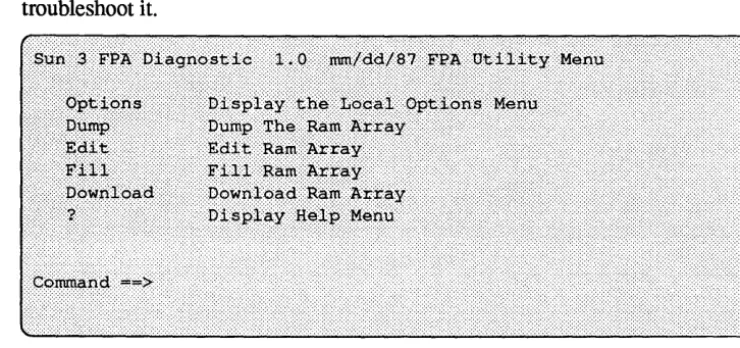
Test Sequence 3 Menu ... 17 6 8.4. Utilities Menu ... 179
Chapter 9 Sun-3/400 Series FPA-Plus Diagnostic ... 183
9.1. General Description ... 183
9.2. What This Chapter Contains... 183
9.3. Overview of the Diagnostic ... 183
-ix-Contents - Continued
9.4. Hardware Requirements ... 183
9 .5. User Interface ... 184
9.6. Starting the Diagnostic ... 184
9. 7. The Diagnostic Menus ... 184
Main Menu ... 184
Command Parameters ... 185
Perfonn All Test Sequence ... 186
Perfonn the Default Test Sequence ... 186
Perfonn the Quick Test Sequence ... 186
Basic Hardware Tests Menu ... 187
Functional Tests Menu ... 187
Tools and Utilities Menu ... 187
Display Current Environment Settings ... 187
Basic Hardware Tests Menu... 188
Register Tests Menu ... 189
Control and Path Tests Menu ... 191
RAM Tests Menu ... 195
Functional Tests Menu ... 202
Functional Tests Menu 1 ... 203
Functional Tests Menu 2 ... 206
Tools and Utilities Menu... 210
Display Current Environment Settings ... 210
DDT Examine Utility... 210
Download to RAM ... 211
Display/Save Test Statistics ... 212
Clear Test Statistics ... 212
Display RAM Error Log ... 212
Clear RAM Error Log... 213
9.8. Error Messages... 213
IERR Register Test ... 213
STATE Register Test ... 213
IMASK Register Test ... 213
LOAD_PTR Register Test ... 213
-x-Contents-Continued
MODE Register Test ... 213
WST A TUS Register Test ... 213
Nack Test... 213
Loop Counter Test ... 214
Pipeline Status Test ... 214
Pipeline Data Test ... 214
Pipeline Instruction Test ... 215
Operand Data Path Test ... 215
TI Data Path Test ... 215
µstore RAM Quick Test ... 215
µstore RAM Data Pattern Test ... 215
µstore RAM Data March Test... 215
µstore RAM Address Unique Test... 216
µstore RAM Address Alternate Test ... 216
µstore RAM Address Disturbance Test ... 216
µstore RAM Address March Test ... 216
Register File Quick Test ... 216
Register File Data Pattern Test ... 216
Register File Data March Test ... 216
Register File Address Unique Test... 216
Register File Address Alternate Test ... 216
Register File Address Disturbance Test ... 217
Register File Address March Test ... 217
Shadow RAM Test ... 217
Micro Store Address Test ... ... 217
NEXT Address Test ... 217
JMP Address Test ... 217
CALL and RETURN Test ... 217
Simple Instruction Test ... 217
Timeout And Retry Test ... 218
Load Pointer Test ... 218
Pointers (1 - 4) Test ... 218
Immed23 Test ... ... 218
-xi-Contents - Continued
Pointer Increment/Decrement Test ... 218
Pointer Five Test ... 219
Lock Test... 219
TI Operation Test... 219
TI Status Test ... 220
Jump Conditions Test ... 220
Pipeline Control (timing) Test ... 220
Pipeline State Machine Test ... 220
9.9. Glossary ... 221
Chapter 10
Floating Point Unit Diagnostic...
22510.1. Overview... 225
10.2. Hardware Requirements... 225
10.3. Diagnostic Functional Description ... 226
10.4. Modular Description Of The Diagnostic... 226
Main Menu ... 226
Registers Test Menu ... 228
Instructions Test Menu ... 229
FPP Test Menu ... 232
10.5. Glossary... 234
Chapter 11
Color Graphics Diagnostic ...
23711.1. Introduction to the Color Graphics Boards ... 237
11.2. What's In This Chapter ... 237
11.3. Objectives... 237
11.4. Required Equipment ... 237
11.5. User Interface... 238
11.6. Set-Up... 238
11.7. Modular Description Of The Diagnostic... 238
The Main Menu ... 238
Manual Test Menu ... 239
Sub-Menus ... 242
Register Test Menu ... 242
-xii-Contents - Continued
Register Test Sub-Menu... 244
Interrupt Test Menu ... 249
Color Map Test Menu ... 249
Frame Buffer Test Menu ... 252
ROPC Test Menu ... 254
Zoom and Pan Test Menu ... 255
DAC Test Menu ... 256
11.8. Auto Test ... 257
DACTests ... 257
Green Ramp Monotonicity ... 259
Blue Ramp Monotonicity ... 259
White Ramp Monotonicity ... 259
Stable Gray Pattern ... 259
Draw Borders ... ... 259
11.9. Interrupt Tests ... 260
11.10. Auto Register Test Details ... 260
Color-5 Auto Register Test ... 261
Color-3 Auto Register Test ... 261
Color-2 Auto Register Test ... 262
11.11. Auto Color Map Test ... ... ... ... ... 262
11.12. Load Colors ... 263
11.13. Frame Buffer Tests: Word Mode and Pixel Mode ... 264
Constant Pattern Test ... 265
Address Uniqueness Test ... 265
Random data test ... 265
Address Test (Modified Galpat) ... 266
Address test (Modified Surround Disturb) ... 266
Refresh Logic Test ... 267
Checker Test (32-bit Word Patterns)... 268
Checker Test (Byte Patterns) ... 268
DMA Window Test ... 268
DMA Width Register Test ... 269
DMA Window Visual Demo ... 269
xiii-Contents - Continued
11.14. Second DAC Auto Test... 269
11.15. Auto Zoom arid Pari Test... 270
11.16. ROPC Tests... 270
11.17. Raridom Data Function Test ... 270
11.18. Implicit word mode Tests... 270
11.19. Pixel Mode Per-Plane Masking Test... 270
11.20. Word Mode Per-Plane Masking Test ... 271
11.21. Error messages ... 271
Register Test Error Messages ... 272
Interrupt Test Error Messages ... 272
Color Map Test Error Messages ... 272
11.22. Glossary ... ... 273
Chapter 12 CG6 Graphics Accelerator Board Diagnostic ... 277
12.1. Introduction... 277
12.2. The Main Menu ... 278
12.3. CG6 Probe Menu ... 279
12.4. TEC Menu... 281
12.5. RDAC Menu ... 284
12.6. FB Memory Menu... 286
12.7. FBC Menu... 289
12.8. THC and Autoload Menu ... 291
12.9. System and Monitor Menu ... 292
12.10. Utilities Menu ... 294
12.11. Option Menu... 297
12.12. Error Messages ... 297
PROBE Error Messages ... 297
TEC Error Messages ... 298
DAC Error Messages ... 299
MEM Error Messages ... 300
FBC Error Messages ... 301
CURSOR Error Messages ... 302
SYS Error Messages ... 302
-xiv-Contents - Continued
UTILITIES Menu Error Messages ... 303
Chapter 13 CG8 Diagnostics ... 307
13.1. Introduction ... 307
13.2. Parameter Definitions ... 307
13.3. The Main Menu ... 309
13.4. Memory Menu... 310
13.5. Register Menu... 315
13.6. Function Menu ... 316
13.7. Pattern Menu ... 317
13.8. Debug Menu ... 319
13.9. Memory Map for Debugging... 320
Chapter 14 CG9 Color Graphics Diagnostic ... 323
14.1. Introduction to the CG9 ... 323
14.2. What This Chapter Contains ... 323
14.3. OveIView of the Diagnostic ... 323
14.4. Hardware Requirements ... 323
14.5. User Interface... 324
14.6. Starting the Diagnostic ... 324
14.7. The Diagnostic Menus... 324
Main Menu ... 324
All Test Sequence ... 325
Quick Test Sequence ... 325
Memory Menu ... 325
Functional Menu ... 326
Pattern Menu ... 326
Debug Menu ... 326
Print Pass-fail Stats ... 326
Initialize Frame Buffer... 326
Memory Menu ... 327
All Test Sequence ... 328
Quick Test Sequence ... 328
-xv-Contents - Continued
Control Space Test ... 328
Constant Data Test ... 328
Walking One Data Test ... 328
Incrementing Data Test ... 329
Random Address and Data Test ... 329
8- and 16-bit Data Size Access ... 329
RAMDAC Address Register Test ... 329
RAMDAC Command Register Test ... 329
RAMDAC Look-up Tables Test ... 329
Initialize Frame Buffer ... 329
Function Menu ... 329
All Test Sequence ... 330
Quick Test Sequence ... 330
Buffer Enable Test... 331
Double Buffering Test ... 331
RGB Mask Control Test ... 331
Line Blit Test (Same Buffer) ... 331
Screen Blit Test (Mixed Buffer) ... 331
RAMDAC Color Look-up Test ... 331
RAMDAC Overlay Look-up Test ... 332
RAMDAC Read Mask Test ... 332
Retrace Interrupt Test ... 332
Initialize Frame Buffer ... 332
Pattern Menu ... 332
All Test Sequence ... 332
Rotate Through 16 Burst Patterns ... 333
Display One Overlay Color ... 333
16 Gray Level Boxes ... 333
Alternating Stripes With Boxes ... 333
Cross Hatch Pattern ... 333
TV Color Bar ... 334
Cycle Through Colors ... 334
Crosstalk Color Memory With Overlay ... 334
-xvi-Contents - Continued
FCC Dither Pattern (Gray Stripes) ... 334
One Pixel Wide Border ... 334
Initialize Frame Buffer... 334
Debug Menu ... 334
Fill Frame Buffer Location(s) ... 335
Edit Frame Buffer Location(s) ... 336
Dump Block of Frame Buffer Data ... 336
Display RAMDAC Overlay or Color Palette ... 336
Scope Frame Buffer Location ... 336
Write-Quick-Read Scope Test ... 337
Bit-bit Horizontal Line ... 337
Bit-bit Line Scope ... 338
Bit-bit Rectangle ... 339
Initialize Frame Buffer ... 339
14.8. Glossary ... 339
Chapter 15 Graphics Processor! Diagnostic ... 343
15.1. Introduction ... 343
15.2. What This Chapter Contains ... 343
15.3. Overview of the Diagnostic ... 343
15.4. User Interface... 343
15.5. Starting the Diagnostic ... 343
15.6. The Main Menu... 343
Run the Slave Tests ... 345
Run the Viewing Processor Tests ... 346
Run Floating Point Tests... 347
Run the Painting Processor Tests ... 347
Test the GB DRAM ... 349
Test the GB Integer Multiplier ... 349
Test the PP PROMs ... 349
Run Scope Loops ... 349
15.7. The Scope Loop Menus ... 350
S - Shared Memory ... 350
xvii-Contents - Continued
M - Micstor Scope Loop ... 351
A - Microstore Address Register ... 351
v -
VP Scope Loop Menu ... 352P - PP Scope Loop Menu ... 356
D - DRAM Scope Loop Menu ... 360
15.8. Error Messages... 361
15.9. Abortion Message Interpretation ... 382
Chapter 16 Graphics Processor2 Diagnostic ... 387
16.1. Introduction to the GP2 ... 387
16.2. What This Chapter Contains ... 387
16.3. Diagnostic Objectives ... 387
16.4. Hardware Requirements ... 388
16.5. Diagnostic Overview ... 388
16.6. The Main Menu ... 389
Shared Memory Tests Menu ... 390
WCS Memory Tests Menu ... 392
XP, RP Processor Tests Menu ... 394
XP, RP Shared Memory Tests Menu ... 398
Test Syntax ... 399
Test Options ... 399
XP, RP Local RAM Menu... 401
FIFO Tests Menu ... 403
FIFO Function Tests Menu ... 403
FIFO RAM Tests Menu ... 407
PP Core Test Menu ... 409
PP Hardware Control Test Menu ... 412
Z (depth) Buffer Test Menu... 415
CG5 Frame Buffer Interface Tests... 417
P2 Bus Interface Test Menu ... 420
CG9 Frame Buffer Test Menu ... 424
Memory Utilities Menu ... 427
Option Menu ... 428
xviii-Contents - Continued
16.7. Memory Test Descriptions ... 429
Addressing Test ... 429
Constant Pattern Test ... 4 30 Checker Pattern Test... 431
Uniqueness Addressing Test ... 433
Mats (Modulo 3's) Test... 433
Walking 1 's/O's Test ... 434
NTA Pattern Test... 435
Random Pattern Test ... 436
Triangle Pattern Test... 437
LRAM, SRAM Bus test... 437
XP Port 2, Port 3 Tests ... 438
XPPort3 VME Test ... 439
XP, RP Arbiter Test ... 440
16.8. XP, RP Processor Tests... 441
Hshake Test ... 441
CHshake Test... 442
XP Branch Tests ... 442
WCS Addressing Test ... 443
XP Logical Test ... 444
XP Register Tests ... 444
XP Push Pop Tests ... 444
XP SOB Test ... 444
XP SOB Neutralize Test... 444
XP SHOB Test ... 444
XP Add, Sub Tests ... 444
XP Call Tests ... 444
XP Condition Code Tests ... 445
XP Merge, Deposit Tests ... 445
XP Extract Tests ... 445
XP Multiply Test ... 445
XP Divide Test ... 445
XP Byte Alignment Test ... 445
-xix-Contents - Continued
XP Byte Store Test ... 445
XP Addrd Test ... 446
16.9. XP Floating Point Tests ... 446
XP Fload Tests ... 446
XP Fabs Tests ... 446
XP Float Tests ... 446
XPFadd Tests... 447
XP Faddt Tests ... 447
XPFadd2 Tests ... 447
XP Fmac Tests ... 44 7 XPFmul Tests ... 447
XP Flut Tests ... 44 7 XP F _cc Tests ... 448
XP Fndloop Tests ... 448
16.10. Shared RAM Comm ... 448
Handshake Communications ... 448
16.11. Error Messages ... 451
Error Message No. 1. ... 451
Error Message No. 2 ... 451
Shared RAM Error Messages ... 451
Arbiter Error Messages ... 452
FIFO Error Messages ... 452
PP Error Messages ... 453
PP Hardware Menu Error Messages ... 455
CG5 Frame Buffer Menu Error Messages ... 456
CG9 Frame Buffer Menu Error Messages ... 457
Z Buffer Menu Error Messages... 458
16.12. Default Test Sequence... 459
16.13. Glossary... 461
Chapter 17
TAAC-1 Applications Accelerator Diagnostic...
46517.1. Introduction to the TAAC-1 ... 465
17 .2. What This Chapter Contains ... 465
-xx-Contents - Continued
17 .3. T AAC-1 Functional Overview ... 465 VME Interface ... 465 Buses and Data Patlls ... 466 Registers ... 467 Vector Ports ... 467 Access Processor ... 467 Video Output ... 467 17.4. Hardware Requirements ... 468 17.5. Set-Up... 468 17 .6. Description Of The Diagnostic ... 469 Main Menu ... 469 Options Menu... 471 Tests Routine Menu ... 476 Interactive Operations ... 476 17.7. TAAC-1 Test Descriptions... 478 Microcode RAM Test... 478 Scratchpad RAM Test ... 4 78 Video RAM Test... 479 Video Registers Test ... 480 Sequencer Functionality Test ... 482 ALU Registers Test ... 482 ALU Operations Test ... 483 Barrel Shifter Test ... 484 Floating Point Operations Test ... 485 Look-up Table RAM and ROM Test ... 486 Multiplier Accumulator Test ... 487 RDRC Test ... 487 Sequencer Stack Test ... 487 Access Processor Test... 488· Vector Port Test ... 490 Vector Port Test (Write Only)... 490 Brooktree RAMDAC Test... 491 Interrupts Test ... 494
xxi-Contents - Continued
Frame Buffer Checksum Test ... 495
Chapter 18 High Speed Serial Interface Diagnostic ... 499
18.1. General Description... 499 18.2. What This Chapter Contains ... 499 18.3. Overview of the Diagnostic ... 499 18.4. Hardware Requirements ... 499 18.5. User Interface... 500 18.6. Starting the Diagnostic ... 500 18.7. The Diagnostic Menus... 500 18.8. Main Menu ... 500 All Sequential Test... 501 Quick Sequential Test ... 501
CIO Menu ... 501 Optional Parameters ... 502 All Sequential Test ... 502 Quick Sequential Test ... 502
CIO A ScoJ>e Menu ... 502 CIO B Scope Menu ... 504
CIO Access Test ... 504
CIO Port Read ... 504
CIO Port Write ... 504
CIO Control Register Read ... 505
CIO Control Register Write ... 505 V.35 Modem Control Test Menu... 505 RS-449 Modem Control Test Menu ... 507 Interrupt Verification ... 508 Parity Interrupt Verification ... 508 Modem Control Interrupt Verification Menu... 509 Dynamic RAM Menu ... 512 Optional Parameters ... 513 All Sequential Test ... 513 Quick Sequential Test... 513
xxii-Contents - Continued
Set Parity Menu ... ... 513 Force Parity Error Test... 514 Address Test ... 514 Pattern Test ... ... ... ... ... ... ... 514 Checker Pattern Test ... 514 Unique Pattern Test... 514
MATS+ Pattern Test ... 514 Random Pattern Test ... 515 NTA Test... 515 Triangle Pattern Test ... 515 Diagonal Pattern Test... 515
DRAM Access Menu ... 516 Serial Controller Menu .. ... ... ... ... ... 519 All Sequential Test ... 519 Quick Sequential Test ... 519 Serial Controller A Scope Menu ... 520 Serial Controller B Scope Menu ... 522 Internal Loopback Menu ... 522 External Loopback Menu ... 523 Port To Port Menu ... 524 Programmable Divider Menu ... 526 Exit... 527 18.9. Messages... 527
CIO Ports A, B, and C and Control Registers Access
Verification ... 527 Successful Completion Messages ... 527 Error Messages ... 528 V.35 Modem Control Test Menu... 528 Successful Completion Messages... 528 Error Messages ... 528 RS-449 Modem Control Test Menu ... 529 Successful Completion Messages ... 529 Error Messages ... 529
xxiii-Contents-Continued
Interrupt Verification ... 529 Successful Completion Messages ... 529 Error Messages ... 529 Parity Interrupt Verification ... 529 Successful Completion Messages ... 529 Error Messages ... 529 Modem Control Interrupt Verification Menu ... 530 Successful Completion Messages ... 530 Error Messages ... 530 Dynamic RAM Address, Pattern, and NT A Tests ... 531 Error Messages ... 531 MK5025 Register Access Verification ... 531 Successful Completion Messages ... 531 Error Messages ... 531 MK5025 A/B Selftest ... 531 Successful Completion Messages ... 531 Error Messages ... 531 MK5025 A/B FCS Check ... 531 Successful Completion Messages ... 531 Error Messages ... 531 Serial Controller A/B Interrupt Verification ... 532 Successful Completion Messages ... 532 Error Messages ... 532 18.10. Glossary... 532
Chapter 19 IPI Disk Subsystem Diagnostic ... 535
19.1. General Description ... 535 19.2. What This Chapter Contains ... 535 19.3. Overview of the Diagnostic ... 535 19.4. Hardware Requirements ... 535 19.5. User Interface ... 535 19.6. Starting the Diagnostic ... 536 19.7. The Diagnostic Menus... 536
xxiv-Contents - Continued
Main Test Menu ... 536 Command Variables ... 537 Local Environmental Variables ... 538 Controller Test Menu ... 539 Drive Test Menu... 543 Utility Menu ... 548 Quick Test Sequence... 554 Default Test Sequence ... 554 All Test Sequence ... 554 Command Default Variables ... 555 Display Error Log ... 555 Clear Error Log ... 555 Exit ... 555 19.8. Error Messages ... 556 19.9. Glossary... 559
Chapter 20 Keyboard Diagnostic ... 563
20.1. Requirements ... 563 20.2. Description ... 563
Chapter 21 MCP/ALM2 Diagnostic ... 569
21.1. Introduction ... 569 21.2. Hardware Requirements ... 569 Loopback Connectors... 569 21.3. Limitations ... 572 21.4. Operating Instructions ... 572 Loading And Starting ... ... ... ... 572 21.5. The User Interface ... 572 Recommended Test Procedure ... 572 The Main Menu ... 573 The Basic Test Menu ... 574 DLF Option Menu ... 577 The Middle Test Menu ... 577
-xxv-Contents-Continued
21.6. The Advanced Test Menu... 580 21.7. Error Handling ... 5 82 21.8. Message Interpretation And Failure Analysis. ... 583 21.9. Status In DEVVEC Patterns ... 597 21.10. Glossary... 599
Chapter 22 MTI/ALM Board Diagnostic ... 603 22.1. Introduction... 603 22.2. Hardware Requirements ... 603 22.3. O_perating Instructions ... 603 Recommended Test Procedure ... 603 The Main Menu ... 6()4 Configuration Selection Sub-Menu ... 605 22.4. Test Descriptions ... 606 Character Data Test ... 606 Block Data Test ... 606 Baud Rate Test ... 606 Stop Bit Test... 607 Word Length Test ... 607 Parity Test ... ... 607 Modem Lines Test ... 607 22.5. Error Handling ... 607 22.6. Glossary ... 608 22. 7. References ... 609
Chapter 23 Sun Memory Diagnostic ... 613 23.1. General Description... 613 23.2. Hardware Requirements ... 613 23.3. The Main Menu... 614 Memory Diagnostic Command Descriptions ... 614 23.4. Glossary... 618
Chapter 24 Parity Diagnostic ... 621
-xxvi-Contents - Continued
24.1. General Description... 621 24.2. What This Chapter Contains ... 621 24.3. Overview of the Diagnostic ... 621 24.4. Hardware Requirements ... 622 24.5. Finnware Requirements... 622 24.6. User Interface ... 622 24.7. Starting the Diagnostic ... 622 24.8. The Main Menu... 622 Optional Parameters ... 623 All Test ... 623 Default Test ... 623 Quick Test ... 623 Options ... 623 Parity... 624 Scope Loop ... 625 24.9. Error Messages... 626 24.10. Glossary... 626
Chapter 25 Sun Mouse Diagnostic ... 629
25.1. General Description... 629 25.2. Command Line Description... 629 25.3. Mouse Data ... 629 25 .4. The Main Menu ... 629 25.5. Error Messages... 631
Chapter 26 Sun Ethernet Diagnostic ... 635
26.1. General Description ... 635 26.2. Hardware Requirements ... 635 Test Overview ... 635 Aborting an Ethernet Test ... 636 26.3. The Main Menu ... 636 26.4. Local Environmental Parameters ... 636 26.5. Ethernet Diagnostic Main Menu ... 638
-xxvii-Contents-Continued
26.6. The Control Interface Menu ... 639 26.7. The Ethernet Menu ... 640 26.8. The Memory Path Menu ... 642 26.9. The Debugging Aids Menu... 644 The Options ... 646
Chapter 27 Second Ethernet Board Diagnostic ... 651 27.1. Second Ethernet Board Overview... 651 27.2. Hardware Requirements... 651 27 .3. Loading And Starting ... 652 27.4. The Main Menu ... 652 27.5. Set Option Sub-Menu... 654 27 .6. Error Messages ... 654 Register Test ... 654 Memory Test ... 655 Pagemap Test ... 655 Internal Loopback Test ... 655
Encoder Test ... 655
External Loopback Test ... 655 27.7. DIAGNOSE Test... 656 Loopback Error Messages ... 656 27.8. Glossary... 658
Chapter 28 FDDI Diagnostic ... 661 28.1. General Description... 661 28.2. What This Chapter Contains ... 661 28.3. Overview of the Diagnostic ... 661 General Tests ... ... 662
RAM Address Test ... 662
RAM Checker Test ... 662 RAM Constant Test ... 662
RAM Diagonal Test ... 662
RAM Triangle Test ... 662
xxviii-Contents-Continued
RAM Unique Test ... 662
RAM MATS Test ... 662
RAM NT A Test ... 663
RAM Random Test ... 663 Read Test ... 663 Write Test ... 663 Write/R.ead Test ... 664 March Test ... 664 Checksum Test ... 664 Tools and Utilities ... 664 28.4. Hardware Requirements ... 664 28.5. User Interface ... 664 28.6. Starting the Diagnostic ... 665 28.7. The Diagnostic Menus ... 665 Main Menu ... 665 Command Parameters ... 666 Environmental Variables ... 667 Diagnostic Tests Menu ... 669 Perform All Test Sequence ... 669 Perform the Default Test Sequence ... 669 Perform the Quick Test Sequence ... 669
VME Interface Tests Menu ... 670 Node Processor Glue Tests Menu ... 670 FDDI Tests Menu ... 670 Scope Loop... 670 Display RAM Error Log ... 670 Clear RAM Error Log ... 670 Display /Save Test Statistics ... 670 Clear Test Statistics ... 671 Display Current Environment Settings ... 671 Diagnostics Tools and Utilities Menu ... 672 Display Current Environment Settings ... 673 Execute Code in NP RAM ... 673
-Contents- Continued
Map Additional FDDI Boards in VME ... 673 Unmap FDDI Board from VME ... 674 Display DUT Memory Map ... 674 DUT Memory Examine Utility ... 674 Tell NP to Reset ... 675 Generate anNMI on NP... 675 Display Controller Status... 675 Download Object Code onto NP RAM ... 676 Download and Execute Object Code on NP RAM ... 676 VME Interface Tests Menu ... 677 Node Processor Glue Tests Menu... 679 FDDI Tests Menu ... 689 28.8. Recommended Testing Sequence... 703 28.9. Messages... 705 28.10. Glossary... 711
Chapter 29
Sun-3/80 ESP SCSI Diagnostic ...715
29.1. General Description... 715 29.2. What This Chapter Contains ... 715 29.3. Oveiview of the Diagnostic ... 715 SCSI Commands ... 715 Error Detection ... ... 716 29.4. Hardware Requirements... 717 29.5. User Interface ... 717 29 .6. Starting the Diagnostic ... 718 29. 7. The Diagnostic Menus ... 718 ESP Subsystem Diagnostics Main Menu ... 718 Parameters ... ... ... ... ... 718 Execute ESP Disk and Tape Tests ... 718 Execute Quick ESP Disk and Tape Tests ... 719 Default Tests ... ... 719 SCSI Host Adaptor Menu... 719 Hard Disk Drive Test Menu ... 720
-xxx-Contents - Continued
Execute All Tests .. ... 720 Execute Quick Disk Test ... 720 Default Disk Tests ... 720 Tape Drive Test Menu ... 722 Sub-system Configuration ... 723 Stop on Error ... 723 Help... 723 SCSI Disk Target Diagnostics Test Menu ... 724 ESP Disk Target Diagnostics Second Menu ... 727 Disk Individual Commands Main Menu ... 728 Disk Individual Commands Second Menu ... 730 Tape Individual Commands First Menu ... 732 Tape Individual Commands Second Menu ... 733 Disk Parameter First Menu ... 734 Disk Parameter Second Menu ... 737 Disk Parameter Third Menu ... 739 Tape Parameter First Menu ... 7 40 Tape Parameter Second Menu ... 7 40 Parameter and Buffer Display Menu... 741 29.8. Supported SCSI Commands ... 742 Internal Embedded-SCSI Quantum Disk Controller Commands ... 743 CDC WREN IV SCSI Disk Controller Commands ... 744 MT02 Tape Controller Commands ... 745 29.9. Messages ... 745 Executive Message Numbers ... 745 Executive Error Numbers ... 746 Message Headers ... 753 29.10. Glossary... 754
Chapter 30 SPARCsystem 330 ESP SCSI Diagnostic ... 757 30.1. General Description... 757 30.2. Hardware Requirements ... 757 30.3. Starting the Diagnostic ... ... 757
xxxi-Contents - Continued
30.4. User Interface ... 757 30.5. The Diagnostic Menus... 757
Disk Controller Diagnostics Menus and Tape Drive
Diagnostics Menus... 758
ESP SCSI Test Menu ... 758 30.6. Glossary ... 760
Chapter 31 SCSI Subsystem Diagnostic ... 763
31.1. Introduction ... 763 31.2. Problem Specification ... 764 31.3. Requirements ... 764 Perfonnance Requirements ... 764 Functional Requirements... 764 Hardware Requirements ... 765 31.4. Operating Instructions ... 765 31.5. Overview of the Diagnostic ... 765 31.6. The User Interface ... 765 The Main Menu ... 766 SCSI Tests Menus ... 767 The SCSI2 Menu ... 767 SCSI3 Menu ... 768 SCSI3(0B) Menu... 770 Controller Tests Menu ... ... ... 771 Diagnostic Command Menu ... 772 Controller Write Command Menu ... 773 Controller Read Command Menu ... 774 Miscellaneous Command Menu... 775 Disk Drive Tests Menu ... 776 Disk Write Test Menu ... 778 Disk Read Test Menu ... 779 Disk Seek Test Menu ... 780 Tape Drive Tests Menu ... 781 31.7. Error Handling... 784
-xxxii-Contents - Continued
31.8. Message Interpretation... 785
31.9. Failure Analysis ... 786
31.10. Glossary... 788
Chapter 32 FDC
Diagnostic ... .,... 79132.1. General Description ... 7Q 1 32.2. What This Chapter Contains ... 7Q l
32.3. Overview of the Diagnostic ... 7Ql 32.4. Hardware Requirements... 7Ql 32.5. User Interface ... 79?..
32.6. Starting the Diagnostic ... -... 792
32. 7. The Diagnostic Menus ... 792 Main Menu ... .,... 793 Continuously Execute All Floppy Disk Tests ... 793 Default FDC Test Sequence ... ,. ... ,... 793 Quick FDC Test Sequence ... ... 793 Floppy Disk Drive Test ... " .. ,... 794 Disk Controller Data Transfer Test ... 795 Stop on [ 1] Error/s ... 795 Help... 795 Floppy Disk Drive Single Tests Menu ... 796 Data Transfer Single Tests Menu ... 797
32.8. Messages... 799 32.9. Glossary ... 800
Chapter 33
Sun SMD Diagnostic ...803
33.1. General Description ... 803 33.2. Hardware Requirements ... 804 33.3. Set-Up Procedures ... 804 Diagnostic Variables ... ... 806 33.4. Main Menu ... 807
33.5. Controller Tests Menu ... 809
33.6. Drive Tests Menu ... 812
-Contents - Continued
33.7. Utilities Menu... 816 33.8. Controller Errors and Their Interpretation ... 818 33.9. Program Reported Errors... 819 33.10. Glossary... 821
Chapter 34
1/2-Inch Tape Diagnostic ...
82534.1. General Description... 825 34.2. Hardware Requirements ... 825 34.3. Set-Up Procedures ... 825 34.4. Menus ... 826 Main Menu ... 827 Controller Tests Menu ... 829 Transport Tests Menu ... 830 Utilities Menu ... 832 34.5. Error Reporting ... 834 Error Messages ... 834 Procedural Error Messages ... 837 Xylogics 472 status codes ... 837 34.6. Glossary ... 838
Chapter
35
Sun Video Diagnostic ... 841 35.1. General Description... 841 Map of Video Frame Buffers ... 841 35.2. Menus ... 842 35.3. Frame Buffer Menu... 844 Pattern Menu ... 846 35.4. Standard Options Menu... 849 35.5. Glossary... 850Chapter 36 Sun Video Monitor Diagnostic ... 853 36.1. General Description ... 853 36.2. Hardware Requirements ... 854 36.3. User Interface ... 854
-xxxiv-Contents - Continued
36.4. Standard Patterns ... 855 36.5. Main Menu... 856 36.6. Monochrome Menu ... 857 36.7. Grayscale Menu... 859 36.8. Color Menu ... 862 36.9. Error Messages ... 865
Chapter 37 Sun VME Interface Diagnostic ... 869 37.1. General Description... 869 37 .2. Hardware Requirements ... 869 37.3. Hardware Set-Up... 870 UUT /fSCPU configuration ... 870 Jumper Placement ... 870 UUT EEPROM ... 870 TSCPU EEPROM ... 871 37 .4. User Interface ... 871 Command Line Description ... 871 Starting the Diagnostic ... 871 Start-up Procedure ... 871 37 .5. The Main Menu ... 873 37.6. The Master Tests Menu... 875 37.7. The Slave Tests Menu... 880 37.8. The Asynchronous Tests Menu ... 884 37 .9. The Debugging Aids Menu ... 891 37.10. The Options Menu... 894 Local Environment ... 897 37 .11. Glossary ... 899 37.12. VMEMapTable ... 901
Appendix A Standalone Cache and ECC Tests ... 909 A. l. Introduction ... 909 A.2. Standalone Cache Test ... 909 How the Cache Functions ... 909
-xxxv-Contents - Continued
A.3. Hardware Requirements ... 910 A.4. Limitations ... 910 A.5. Loading and Starting... 910 User Command Interface ... 911 Option Menu ... 913 The Cache Data Tests Menu ... 914 Cache Tags Tests Menu... 915 The Cache Read Hit Tests Menu ... 917 The Cache Write Hit Tests Menu... 918 Cache MMU Protection Menu ... 919 The Cache Read Miss Tests Menu ... 919 The Cache Write Miss Tests Menu ... 920 The Cache Write back Error Tests Menu ... 921 The Cache Flush Tests Menu ... 922 The Cache Physical Address Compare Tests Menu ... 923 The Exerciser Tests Menu ... 924 Exerciser Test Sequence ... 925 A.6. Test Descriptions ... 925 Cache Data Write/Read Test... 925 Error Description ... 925 Cache Data Pattern Write/Read Test ... 926 Error Description ... 926 Cache Data Address Test ... 926 Error Description... 926 Cache Inverse Data Address Test ... 926 Error Description ... 926 Cache Data Walking Ones Test ... 926 Error Description ... 926 Cache Data Walking Zeros Test ... 926 Error Description ... 926 Cache Data 3-Pattem Test ... 927 Error Description ... 927 Cache Data March Test ... 927
-xx.xvi-Coatents - Continued
Cache T~s Write/Read Test ... 927 Erro.r Description ... 927 Cache Tags Pattern Write/Read Test ... 927 Error Description ... 927 Cache Tag Address Test ... 928 ErJOr Description ... 928 Cache Inverse Tag Address Test ... 928 Error Description ... 928 Cache Tags Walking Ones Test ... 928 Error Description ... 928 Cache Tags Walking Zeros Test ... 928 Error Description ... 928 Cache Tags 3-Pattem Test... 928 Cach.e Tap March Test ... 929 Cache Read Hit Test ... 929 Error Desc~ ... 929 Cacl~ llead Hit (context different) Test ... 929 Error Descripti.on ... 930 Cache Read Hi>t Byte Alignment Test ... 930 Error Description ... 930 Cache First Write Hit Test... 930
Erri0.r De.sc~n ... 931 Cacae Modify Write Hit Test ... 931 Error Description ... ... ... ... 931 Cache Write Hit Byte Alignment Test ... 932
Error Description ... 932 ~U Pr<>tectic>n Test ... 932 Error Descriptions ... 932 Cache :Read Miss/No Writeback (rot dirty) Test ... 932 Error Description ... 933 Cacae Read Miss/Writeback (valid & dirty) Test... 933 Error De.scwption ... 933 Cache Read (Not Dirty)/Physical Address Compare Test ... 934
xxxvii-Contents - Continued
Cache Read (Dirty)/Physical Address Compare Test ... 934 Cache Read (uncached)/Physical Address Compare Test ... 934 Cache Write Miss/Writeback Timeout Error Test ... 934 Error Descriptions ... 934 Cache Read Miss/Writeback Timeout Error Test ... 935 Error Description ... 935 Cache Write Miss/Writeback Translation Error Test ... 935 Error Description ... 935 Cache Read Miss/Writeback Translation Error Test ... 935 Error Description ... 936 Cache Flush (context match) Test... 936 Error Descriptions ... 936 Cache Flush (segment match) Test ... 936 Error Description ... 936 Cache Flush (page match) Test ... 937 Error Description ... 937 Cache Exerciser Tests ... ;... 937 Cached Memory Write/Read Test ... 937 Error Description ... 937 Cached Memory Write/Flush/Read Test ... 937 Error Description ... 938 Cached Fetch NOP Test ... 938 Cached Execution Memory Write/Read Test ... 938 A.7. Test Sequences ... ;... 938 Quick Test ... 938 Default Test ... ... 938 Single Pass Default Test ... 938 Long Test ... 938 Exerciser Test ... 938 A.8. Glossary... 939 A.9. Standalone ECC Memory Diagnostic ... 941 A.10. Introduction... 941 A.11. Hardware Requirements ... 942
xxxviii-Contents - Continued
A.12. Overview Of The Diagnostic... 942 Memory Interface ... 942 Error Checking Correction Interface ... 94 3 Refresh ... 94 3 Initialization ... 944 A.13. Loading And Starting... 944 A.14. User Interface... 945 The Command Line Language ... 945 Main Menu ... 945 Option Menu ... 948 Memory Data Menu ... 950 ECC Test Menu ... 956 Utility Menu ... 960 A.15. Error Handling... %2 ECC Errors ... %2 ECC Test Error Messages ... 962 ECC Data Compare Error ... 962 EDC Forced Error ... 9{i.2 Refresh Scrub Errors ... %3 Bus Errors ... 963 Data Compare Errors ... 963 A.16. Special Problems ... 963 A.17. Replacing the Memory Board ... 963 A.18. Recommended Test Procedure ... 964 A.19. Glossary ... 964 A.20. Syndrome Decode Table ... 966
Appendix B Loopback Connector Pin Designations ... 969
B.1. Serial Port Loopback Connectors ... 969 RS-232 Serial Port Connector ... 969 9-pin L()(){)back Connector ... ~10 RS-232 Loopback Cable ... 91() Ethernet Loopback Connector ... 972
-xxxix-Contents - Continued
Appendix C
Diagnostic Executive Bug Report Form ...97 5
C.1. Overview... 975 C.2. Where to Send the Report... 975 C.3. Who We Can Contact ... 975 C.4. Description of Problem ... 976
-xl-Tables
Table 2-1 MC68020, MC68030 Tape Contents-see next page ... 10 Table 2-2 SPARC Tape Contents... 12 Table 2-3 Tape Contents/System Architecture Matrix ... 13 Table 2-4 Tape Contents/System Architecture Matrix, Continued... 14
Table 8-1 Index Values ... 170 Table 8-2 Testnum Values ... 177 Table 8-3 Index Values ... 179
Table 11-1 Single Honzontal Ramp Test Values... 258 Table 11-2 Red Ramp Monotonicity ... 259 Table 11-3 Stable Gray Pattern Values ... 259 Table 11-4 Draw Borders Test Color Map Values ... 260 Table 11-5 Draw Borders Test FB Values ... 260 Table 11-6 Interrupt Test Sequence ... 260 Table 11-7 Color-5 Auto Register Test Values ... 261 Table 11-8 Color-3 Auto Register Test Values 261 Table 11-9 Color-2 Auto Register Test Values 262
Table 11-10 Auto Color map Test Values 263
Table 11-11 Load Colors ... ,,... :264 Table 11-12 FB Constant Patterns ... , ... , ... : ... ;...;;;,... 265 Table 11-13 Address Test (galpat) ... ;.;.; .. '. .. '. ... ,, .... , ... ,.u~ ... ,~'.... 266 Table 11-14 Gal pat test Algorithm ... , ... '. ... , .... :... 266 Table 11-15 Surround Disturb Test Addresses ... ,, .. >... 267
-xli-Tables - Continued
Table 11-16 Surround Disturb Algorithm ... 267 Table 11-17 Refresh Logic Algorithm ... 267 Table 11-18 Checker Test (word) Patterns ... 268 Table 11-19 Checker Test (byte) Patterns ... 268 Table 11-20 DMA Window Test... 269 Table 11-21 ROPC Tests... 270 Table 11-22 Pixel Mode Per-Plane Masking Test ... 271 Table 11-23 Color Diagnostic Error Code Table ... 271
Table 12-1 CG6 Submenus ... 279 Table 12-2 TEC and THC Registers... 282
Table 13-1 Memory Designations ... 308 Table 13-2 Walking One Pattern... 311 Table 13-3 Walking Zero Pattern ... 311 Table 13-4 Wedge One Pattern... 312 Table 13-5 Wedge Zero Pattern ... 312 Table 13-6 Address-Up Pattern... 312 Table 13-7 Address-Down Pattern... 313
Table 16-1 Integer Float Conversion ... 446 Table 16-2 Float Integer(fixr) Conversion ... 447 Table 16-3 Fmul Test Data... 447 Table 16-4 The Data Block ... 448 Table 16-5 Status Register Bit Definitions ... 449 Table 16-6 Default Tests ... 459
Table 26-1 Intel Ethernet Chip Status Levels ... 645 Table 26-2 AMD Ethernet Chip Status Levels ... 645
Table 33-1 Supported Disk Drives ... 803 Table 33-2 Disk Controller Boards ... 803 Table 33-3 Test Parameter Values... 811 Table 33-4 Num Parameter Values... 812
xlii-Tables - Continued
Table 33-5 Pattern Test Values... 814 Table 33-6 Xylogics 450/451 Error Numbers (in Hex) ... 818
Table 34-1 Tape Diagnostic Error Messages ... 835 Table 34-2 Xylogics Tape Controller Status Codes ... 837
Table 35-1 Values Used in NT A Test ... 845 Table 35-2 Color Values ... 846
Table 37-1 VME Map Table... 901
xliii-Figures
Figure 1-1 RS-232 ConnectiOf'l'S ... 6
Figure 6-1 Sun-3/80 Parallel Port Connector ... 146
Figure 8-1 The FP A Diagnostic Menu Hierarchy ... 166
Figure 20-1 Type-3 Keyboard... 563 Figure 20-2 Type-4 Keyboard ... 564
Figure 21-1 RS-232 Loopback Signals, Asynchronous-only Ports ... 570 Figure 21-2 RS-232 Loopback Signals, Synchronous Ports ... 570 Figure 21-3 RS232 Loopback Signals, Synchronous/Asynchronous
Ports... 570 Figure 21-4 RS449 Loopback Signals, The Two RS449 Synchronous
Ports... 571 Figure 21-5 Parallel Printer Port Signals, DB25 Plug With Loopback ... 571 Figure 21-6 ALM-2/MCP DIP Switches ... 573
Figure 36-1 Monochrome Video Pattern Menu ... ., ... '. •. ,,,.,.; ... , .• , ... ,; .. ,.,:;:;:'.,···:"-.·<:::>:>u..J.,
Figure 36-2 Grayscale Video Pattern Menu ... '''''·'··,~····••··"-.·:·~~·~····,., ... , .... .,.,, ... '..<:<:::: .. ,_.J:~:"
Figure 36-3 Color Video Pattern Menu ... : ... ,,,, ... " ... ,,:,:,:,:,, .... ,,;,. ... .,::::::::::vu ...
-xlv-Figures - Continued
Figure B-2 RS-232 Loopback Cable ... 971
-xlvi-1
Introduction
Introduction ... 3
1.1. Audience
1.2. Common Terms
1.3. Conventions
Fonts
1
Introduction
TM
This manual describes the programs on the SunDiagnostic Executive tape. This chapter provides information about the diagnostic environment in general. The remaining chapters describe the Executive and the Diagnostic Programs them-selves.
This manual is intended for use by personnel in field service, repair depots, manufacturing, and "self-maintaining" customer sites. We assume that the reader is familiar with Sun systems and with diagnostic practices.
The following list defines some words used in this manual:
Diagnostic - a program designed to test parts of the Sun workstation and return messages describing what it found. Each diagnostic covers a particu-lar PC board or subsystem: for example, cpu4 . exec tests the CPU board, and mem4. exec tests the memory.
Executive Tape-A 1/4" or 1/2" magnetic computer tape that contains the Executive and the Diagnostic Programs. Note that you may install these programs on the disk, or boot them direct! y from the tape.
Exec - describes the SunDiagnostic Executive, an operating system that provides a platform for Sun diagnostics and runs independent of the
TM
SunOS .
In this manual, different fonts are used to make things clearer. The most com-mon fonts are Roman, Courier, Courier bo1d, Italic, and Roman bold. They are used as follows:
Roman
Roman font is the standard for normal text, just as it appears here. Roman Bold
Bold Roman font indicates that something deserves more attention than the surrounding text.
Courier
Courier font has two meanings, depending on where it appears. It may represent something that appears in the manual exactly as the computer displays it on the screen, or it may represent a program path/name.
4 SunDiagnostic Executive User's Guide
Hexadecimal Values
1.4. References
1.5. The Exec Tape
1.6. Organization of This
Manual
Courier bold
Courier bo1d font represents something that you must type verbatim into the computer. This sometimes appears together with Courier font: the computer output appears in Courier, and what you must type appears in Courier bold.
Italic
In this manual Italic font usually represents a variable for which you or the computer must provide the exact details. For example:
Italic font is also used for emphasis, special notes and to reference docu-ments.
Hexadecimal values are represented throughout this manual with ''Ox'' preced-ing the value and sometimes replacpreced-ing the value's leadpreced-ing zeroes.
See the following documents for further infonnation:
o The Field Service Manuals for your system for a CPU board overview and hardware assembly procedures.
o The Hardware Installation, CPU board configuration, and slot assignment documents for your system, which provide infonnation on cabling as well as board and system configuration.
o The System Administration Manual for your version of Sun software, which describes various system operations, including the use of the disk formatting facifity, format.
o The PROM User's Manual, and subsequent addenda in the SunOS Release Notes, which contain additional infonnation on EEPROM programming. This manual contains a chapter describing every diagnostic on the tape version released as of the date of this writing. This manual references the 1/4-inch or 1/2-inch SunDiagnostic Executive tapes, Part Numbers 700-2180 and 700-2181 or700-2182 and 700-2183. One set of tapes supports Sun-3 systems, while the
TM
other supports Sun-4 (SP ARC ) systems. The diagnostic programs may either be booted directly off this tape, or copied onto a disk and booted from it. Chapter 2 provides a table of contents for each tape set, as well as a matrix that shows which tape files are intended to support which Sun architectures.
The first two chapters cover the Exec in general and the operating system, or underlying "Executive" platfonn of this diagnostic. The names of subsequent chapters reflect the hardware that each diagnostic tests. Diagnostics that test simi-lar hardware are grouped together, so that the chapters describing graphics accelerator boards, for example, would be found in the "Graphics Diagnostics" section. Each chapter includes menu and test descriptions. The appendices cover standalone diagnostics that are included on the tape, pin designations for loopback connectors, and a "bug report" form.
Chapter 1 - Introduction 5
1.7. Required Equipment
The SunDiagnostic Executive requires this functional hardware:1.8. Software
Requirements
Configuring a Terminal
o Memory - lMbyte minimum
o Sun-3 or Sun-4 CPU (MC68020, MC68030 or SF9010IU)
o TheMMU
o Real-time clock
o The system must have at least one of the following: Console and Keyboard
A terminal connected to Serial Port A A modem connected to Serial Port B
o A boot path to a storage device:
A hard disk controlled by SCSI, s d ( ) , or Xylogics, xy ( ) or xd()
A 1/4-inch tape controlled by SCSI, st ()
A 1/2-inch tape, mt () or xt ( )
An Ethernet controller on a server, ie () or le ()
o Serial Port Loop back connectors, required for CPU board diagnostics.
o Additional equipment requirements are listed where necessary. Refer to
Appendix B for CPU board loopback connector pinouts.
The following software must be available to boot from the system under test:
o The SunDiagnostic Executive
o A set of Diagnostic Programs (in the diags file) that run under the Exec.
NOTE The Diagnostic programs and the Exec must all be at the same revision level (i.e. all from the same tape). The old standalone diagnostics won't work with the Exec, although there are four such programs included on the tape that can be individually booted or copiedfrom tape.
The Exec software may be booted from tape or disk, or booted remotely across the Ethernet.
You may execute the Exec from a "dumb,, terminal. To set up the terminal: Use an ASCII or ANSI terminal, set up as follows:
Full Duplex 9600 baud XONand XOFF 8 bits/1 stop bit No parity
Connect the terminal to the connector labeled Serial Port A at the rear of the system.
6 SunDiagnostic Executive User's Guide
Figure 1-1
SIO-A
The cable you use should be wired as follows: Cross-connect pins 2 and 3
Loop back pins 5 and 6 at both ends Connect pin 7 straight through
See the following figure:
RS-232 Connections
Pin2 Pin2
Pin3 Pin 3
Pin 7 Pin 7
Pin5 Pin5
Pin 6 Pin6
Tenninal
Later, when you have activated the monitor, use the Exec commands to redirect the input and output as you wish.
2
Using
the SunDiagnostic Executive
Using the SunDiagnostic Executive ...
9
2.1. What This Chapter Contains ... 9 2.2. History ... 9
2.3. Overview ... 9 2.4. The Exec Tape ... 10 2.5. Loading and Booting the Exec... 14 2.6. The Exec Environment ... 22 2.7. User Interface ... 25
2.1. What This Chapter
Contains
2.2 .. History
2.3. Overview
2
Using the SunDiagnostic Executive
This chapter contains an oveIView of the SunDiagnostic Executive, a description of the release tape contents, loading and booting instructions, and a description of the Exec menu selections and their required command syntax. Subsequent chapters discuss the individual diagnostics that run under the Exec.
Originally, each Sun diagnostic program ran as a "standalone", without the SunOS operating system. They lived in the
I
stand directory, and each pro-gram was booted from the PROM monitor. This directory contained an inventory of diagnostic programs, typically one per system PC board or major function. This arrangement had two significant limitations. First, only one diagnostic pro-gram could run at a time. This made it hard to load down the system for a thorough test, and it took a long time to test more than just a few components. Second, each diagnostic program had its own particular user interface which made the tests hard to use.The SunDiagnostic Executive provides a single, unified diagnostic environment with only one user interface. The diagnostic tests still reside in individual pro-grams within Is tand, but they all work through the SunDiagnostic Executive (hereafter called the Exec) platform. The platform provides a consistent interface and multitasking capabilities. In addition, the Exec provides the functionality listed below, which is available to any diagnostic. Some Exec features are:
o Multiple consoles: You can configure the Exec to run from any control
ter-minal. This device may be the Sun monitor, Serial Port A, Serial Port B, or a remote console. Multiple terminals can also be connected to a system, and each used for input and output.
o Error Logging: The Exec provides the ability to capture error messages into a logfile. This logfile may reside either on a local disk or on the seIVer.
o Script Execution: You may write command scripts to automatically drive
the menus without further user input.
o Remote Execution: One of the special features of the Exec is the ability to
perform remote diagnostics over a modem connected to a Serial Port, or by way of Ethernet. Any diagnostic that runs under the Exec execution plat-form can be used remotely.
10 SunDiagnostic Executive User's Guide
The Exec has one Main Menu that appears when the you boot. Commands in this main menu call up the Environment Menu, Options Menu, Diag-nostics Menu, Status Menu, and a Log Menu. Each diagnostic has its own menu, called up from the Diagnostics menu.
NOTE In this document, the menus shown are examples only; the menu you see on the screen may differ slightly from these examples.
2.4. The Exec Tape
The Exec release tape contains boot programs, the Exec program itself and the diagnostics that currently run under the Exec. The following pages show Sun-3TM
and Sun-4 (SP ARC ) tape contents, along with a table that shows which tape files support which Sun architectures. Two "standalone" diagnostics,
eccmem. diag, cache. diag, are included on the tapes for each architecture. They are designed to test Sun-3/200 and Sun-4/200 series workstation memory. These standalone tests do not function as part of the SunDiagnostic Executive. They may be extracted from tape and executed separately. Documentation for these tests is in Appendix A.
NOTE The user interj ace for the standalone tests is not the same as that described here for Diagnostics Menu choices.
The table on the following page lists the contents of the 1.2 SunDiagnostic Exe-cutive Sun-3 tape, for MC68020 and MC68030-based workstations. The part number for the 1/4-inch tape is 700-2180; the part number for the 1/2-inch tape is 700-2181.
Table 2-1 MC68020, MC68030 Tape Contents-see next page
~\sun
~~
Chapter 2 - Using the SunDiagnostic Executive 11
Name File Sun-3 Tape Contents Description Number
(decimal)
tpboot020 0 enables Sun-3 boot from tape
tpboot030 1 enables Sun-3/400 Series, Sun-3/80 boot from tape toe 2 Contains list of contents of this tape
extract_ exec 3 Script to copy diagnostics to disk Copyright 4 Textfile containing copyright notice
exec 5 The SunDiagnostic Executive for Sun-3 architecture
exec3x 6 The SunDiagnostic Executive for Sun-3/400 Series and 3/80 diags 7 Diagnostics Menu and File names (used by Exec)
cg6.exec 8 P4 Low-End Graphics Accelerator cg8.exec 9 P4 24-Bit Frame Buffer Board Diagnostic cg9.exec 10 VME 24-Bit Frame Buffer Board Diagnostic color.exec 11 Generic VME Color Board Diagnostic cpcache.exec 12 Sun-3/400 Series Cache Diagnostic cpu.exec 13 Sun CPU Diagnostic
eeptool. exec 14 EEPROM programming tool ether.exec 15 Sun Ethernet Diagnostic ether2.exec 16 Ethernet II Diagnostic exectest.exec 17 Exec Verification Suite
fdc.exec 18 On-Board Floppy Disk Controller Diagnostic fddi.exec 19 FDDI Board Diagnostic
fpa.exec 20 Sun-3 Floating Point Accelerator Diagnostic
fpa_plus.exec 21 Sun-3/80 Floating Point Accelerator Plus Diagnostic gpl.exec 22 Graphics Processorl/Graphics Buffer Diagnostic gp2.exec 23 Graphics Processor2 Diagnostic
hss.exec 24 High Speed Serial Interface Diagnostic iocache.exec 25 Sun-3/400Series1/0 Cache Diagnostic ipi.exec 26 IPI Disk Subsystem Diagnostic
kb.exec 27 Sun Keyboard Diagnostic
mcp.exec 28 Sun ALM2/MCP Board Diagnostic mem.exec 29 Sun Memory Diagnostic
mempar.exec 30 Sun-3/80 Parity Memory Diagnostic mouse.exec 31 Sun Mouse Diagnostic
mti.exec 32 Sun MTI/ ALM Board Diagnostic scsisub.exec 33 SCSI Subsystem Diagnostic espscsi.exec 34 ESP SCSI diagnostic smd.exec 35 Sun SMD Diagnostic
taac.exec 36 T AAC-1 Accelerator Diagnostic tape.exec 37 Pertee 1/2-inch Tape Diagnostic video.exec 38 Video Circuitry Diagnostic vidmon.exec 39 Sun Video Monitor Diagnostic vme3.exec 40 Sun VME Diagnostic
netcon 41 Network Console Program logfile 42 Error Log File
eccmem3.diag 43 Standalone ECC Memory Diagnostic cache3.diag 44 Standalone Cache Memory Diagnostic
12 SunDiagnostic Executive User's Guide
The table below lists the contents of the 1.2 SunDiagnostic Executive Sun-4 tape, for SPARC-based workstations. The part number for the 1/4-inch tape is 700-2182; the part number for the 1/2-inch tape is 700-2183.
Table 2-2 SPARC Tape Contents
Name File Decription-Comments
Number (decimal)
tpboot.sun4 0 enables boot from tape
Copyright 1 Textfile containing copyright notice toe 2 Contains list of contents of tape extract_exec 3 Script to copy diagnostics to disk Copyright 4 Textfile containing copyright notice
exec4 5 The SunDiagnostic Executive for SP ARC architecture diags4 6 Diagnostic Menu and File names (used by Exec) cg6.4.exec 7 P4 Low-End Graphics Accelerator
cg8.4.exec 8 P4 24-Bit Frame Buffer Board Diagnostic cg9.4.exec 9 VME 24-Bit Frame Buffer Board Diagnostic color4.exec 10 Generic VME Color Board Diagnostic cpcache4.exec 11 CPU Cache for SP ARCsystem330 cpu4.exec 12 Sun CPU Board Diagnostic eeptool4 .exec 13 EEPROM programming tool ether4.exec 14 Sun Ethernet Diagnostic ether2.4 .exec 15 Ethernet II Board Diagnostic . exectest4.exec 16 Exec Verification Suite fddi4.exec 17 FDDI Board Diagnostic
fpu4.exec 18 Sun-4 Heating Point Unit Diagnostic
gpl.4.exec 19 Graphics Processorl/Graphics Buffer Diagnostic gp2.4.exec 20 Graphics Processor2 Diagnostic
hss4.exec 21 High Speed Serial Interface Diagnostic ipi4.exec 22 IPI Disk Subsystem Diagnostic
kb4.exec 23 Sun Keyboard Diagnostic
mcp4.exec 24 Sun ALM2/MCP Board Diagnostic mem4.exec 25 Sun Memory Diagnostic
mouse4.exec 26 Sun Mouse Diagnostic
mti4.exec 27 Sun MTI/ ALM Board Diagnostic scsisub4 .exec 28 Sun SCSI Subsystem Diagnostic
espscsi4 .exec 29 SP ARCsystem330 ESP SCSI Diagnostic TM smd4.exec 30 Sun SMD Diagnostic
tape4.exec 31 Pertee 1/2-inch Tape Diagnostic video4.exec 32 Sun Video Circuit Diagnostic vidmon4.exec 33 Sun Video Monitor Diagnostic vme4.exec 34 Sun VME Diagnostic
netcon4 35 Network Console Program logfile 36 Error Log File
eccmem4.diag 37 Standalone ECC Memory Diagnostic cache4.diag 38 Standalone Cache Memory Diagnostic
Chapter 2 - Using the SunDiagnostic Executive 13
The table below shows all the files found on both the Sun-3 and Sun-4 tapes, and indicates with an "x" which archi-tecture is supported by that file.
Table 2-3 Tape Contents/System Architecture Matrix
File System Architecture Supported
Sun-3 Sun-3E Sun-3180 or 31400 Sun-4 SPARCsystem 330
exec x x
exec3x x
exec4 x x
cg6 3/60 only 3/400 x x
cg8 x x x x
cg9 x x x x
color x x x x
cpcache 3/400 only x x
cpu x x x x x
eeptool x x x x
ether x x x x
ether2 x x x x
fdc x
fddi x x x x
fpa x x
fpa_plus x
fpu x x
gpl x x x x
gp2 x
x
x xhss x x x x
iocache 3/400 only
ipi x x
x
xkb x x x x x
mcp x x x x
mem x x x x x
mempar 3/80 only
mouse x x x x x
mti x x x x
scsisub x x x
espscsi 3/80 only x
espscsi4 x
smd x x x x
14 SunDiagnostic Executive User's Guide
Table 2-4 Tape Contents/System Architecture Matrix, Continued
File taac tape video vidmon vme eccmem3.diag cache3.diag eccmem4.diag cache4.diag
2.5. Loading and Booting
the Exec
Before Booting
Halting the System
System Architecture Supported
Sun-3 Sun-3E Sun-3180 or 31400 Sun-4 SPARCsystem 330
x x x x x x x
x x x
x x x
x x x x
x x x x
x x
x x
The files on the tape are stored in tar format, on either a 1/4-inch, QIC24 for-mat tape cartridge, or a 1/2-inch, 6250 BPI Storage Module Device tape.
The Exec may be booted directly off this tape, or the contents can be stored in a SunOS directory for later use.
Unless you boot from tape, the Exec loads its programs from SunOS files located on a hard disk. Although the files can be in any directory, we strongly urge you to keep them in the I stand directory. This document will assume the Exec an its diagnostic programs are all in I stand.
The Exec cannot function unless the system has a minimum amount of functional hardware. The Exec depends on the system self-tests