INTRODUCTION
A
Programmer's Guide 1Q the X-6 Assembly System is concerned wi th the prepara tion of a da ta pro,cessing program for the X-6assembly on a USS 80 or 90 Tape System. For the most part, this consists of the coding of the object program according to X-6 symbolic and relative coding conventions and the pre-paration of the punched card input deck to be processed by
the X-6 Assembly System program. Such preassembly prepara-tions are covered in detail. An understanding of the reasons for these preparations, however, is only possible through a general knowledge of the processing steps during the actual assembly by the X-6 system. For this purpose, a general des-cription of the X-6 processing has been included. The details of the processing can be found in the flow charts of the X-6
Assembly System. .
Most of the examples used are applicable to both the USS 80, 80 Tape, and 90 Tape computers. Some,however, are inimical
~'"' loU U.l..l.C ,",,,",,, ,..."I'YlV"\"+,, .... \...Ulll!!LA.uC.l. (.p" .... \.l.V.l. r.-v-.-,mnl" v~q.l.l.LJ:-'...L-C:;' +h'Y't"'IC) l'"'\!:l'Y'+ !:llnh!:l'hClt;('>~ Qnrl ;1"'1_ U.L.L..L.vv t'~..L U ~~.t-''''..L ... u ' - ' u ... '-'~ ... " " ...
ter laces) •
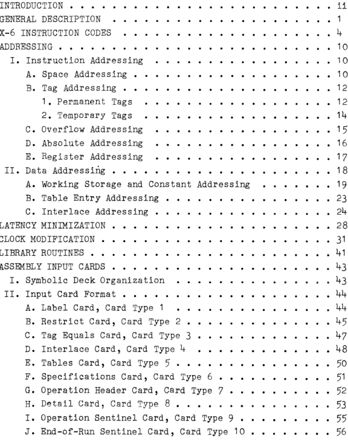
TABLE OF CONTENTS
INTRODUCTION • • • • • •
G~NERAL DESCRIPTION
X-6 INSTRUCTION CODES
.
.
.
ADDRESSING • • • • • • •
·
.
I. Instruction Addressing
·
.
.
. .
·
.
.
A. Space Addressing • • • • B. Tag Addressing • • • • • • •
1. Permanent Tags
.
. .
.
.
2. Temporary Tags
C. Overflow Addressing
.
.
.
.
.
·
. . .
·
.
.
.
·
.
· .
.
· .
.
.
·
. .
.
·
.
.
.
.
· .
.
. .
·
.
·
.
· .
.
.
· .
.
. .
.
.
.
·
.
.
.
.
.
. .
. . .
·
.
.
.
· i i
• 1
• 4
• 10
• 10
• 1 0 12
• 12
• 14
.15
D • Absolute Addressing • • • • • • • • • 16
E. Register Addressing • • • • • • • • • • • • • • • • • 17
I I. D a t a Ad d res s i
n.g • • • • • • • • • • • • • • • • • • • • •
1 8A. Working Storage and Constant Addressing • s • • • • • 19
B. Table Entry Addressing • • • • • • • • • • • • • •
23
C. Interlace Addressing
· . . .
.
.
· • 24.
. .
· .
·
.
.
· .
• 28LATENCY MINIMIZATION • CLOCK MODIFICATION • LIBRARY ROUTINES • • • •
· . • . • . . . • 31
· .
.
.
·
.
.
• • • • • • • 41ASSEMBLY INPUT CARDS
·
.
.
• • • • • • 43I. Symbolic Deck Organization II. Input Card Format • • • • •
A. Label Card, Card Type 1
· . . .
.
.
·
.
.
.
43
• • 44
· .
.
·
.
.
.
• • • • • • 44B. Restrict Card, Card Type 2 • • • • •
• • . • . • 45
C. Tag Equals Card, Card Type 3 • • • . • • . • • • 47
D. Interlace Card, Card Type 4
.
.
· .
.
·
.
• • • • • • 48E. Tables Card, Card Type
5 . .
.
.
·
.
.
.
· .
. . .
• • 50
F. Specifications Card, Card Type 6 •
· .
.
.
. . .
• 51
G. Operation Header Card, Card Type 7 •
·
.
· .
• 52
H. Detail Card, Card Type 8 • • •• ••
· 53
I. Operation Sentinel Card, Card Type 9 •
·
.
·
.
.
· • • 55
J. End-of-Run Sentinel Card, Card Type 10
·
.
.
.
.
• •• 56
OUTPUT CARD FORMAT • • • • • • • • • • • • • • • • •• • •
57
PROGRAMMING PROCEDURES • • • • • • • • • • • • • • • • • •
58
I. Flow-Charting • • • • • • • • • • • • • • • •
58
II. Coding • • • •• •• • • • • • • • • •
59
PREPARATION FOR THE X-6 ASSEMBLY • • • • • • •• • 60
OPERATING INSTRUCTIONS FOR THE X-6 ASSEMBLY • • • • • • • 61
I. Loading and Assembly •
II. Error Codes
.
.
.
.
.
III. Stop Codes • • • • • • IV. X-6 Storage Layout ••
.
.
.
.
.
.
.
.
.
.
.
.
.
.
..
..
.
.
.
.
. . .
. .
.
. .
.
. .
·
.
• 61• • • • • 62
• • • • • 63
• • • • 64
APPENDIX I - OPERATIONS AND SUBROUTINES
WITHIN THE X-6 ASSEMBLY SYSTEM PROGRAM
. .
.
.
. . .
• • 67
GENERAL DESCRIPTION
wnen the X-6 coding of a data processing program or operation has been completed, this coding, and any further information required by the X-6 Assembly System for the processing of the coding, is punched on appropriate input card types. These in-put cards are then placed in a specific order in the inin-put deck and the actual assembly is begun.
Each card type will be processed in a specific way:
I
I IIS8
L _________ _
loom I
I
~--- ---.-.
, -
-I
I The fields of the label card are placed in the output interlaces
without modification.
~---~---
---I
I _
~---Restrict card entries are used to mark off locations in the storage availability table. No restricted location will be assigned when : absol ute addresses are generated. ,
~---'
I I
- ____ - - - ___ - __________________ - - - ___________ - - - ____________________________________ _ -=J--¥, _ _____ _
Tag equals card entries are filed in internal tables equated to their absolute addresses. The absolute addresses are used to mark off locations in the storage availability table.
~---
,
~---~---~
: Interlace card entries are used to mark off interlace positions in : the storage availability table. The origins are filed for future use. :
, ,
.---,
,
1---1
,
, Table card entries are also used to mark off positions in the
storage availability table. Increments and origins are filed for
, future use. ,
~---,
,
:---, : Card types 1 through 5 must be received by the X-6 Assembly System
in order. After the Label card has been processed (MC 1 IN), if a card is received that is not a type 2, 3, 4, or 5, the assumption , is made that all the above processing has been accomplished. ,
~---~
r---~---,
I Specifications card entries are filed in tables for direct
sub-, stitution later. :
,---~
,
.---.
: Operation Header card entries are placed in the output interlaces. ' , Initial conditions are set for Detail card processing (MC 9 5N). ,
!
---Detail cards contain the instruction lines and constants of a
program. Only Detail card processing will produce output punching. The four basic steps in Detail card processing are:
1. Handle the a address.
2. Analyze the instruction code and separate instructions from constants. For instructions, obtain a code word to control further processing by the use of the
necessary increment needed between the a, m, and c
addresses and substitute the computer code equivalent of the mnemonic code. Determine if one or both of the m and c addresses are significant.
3. Handle the m address if necessary.
4. Handle the c address if necessary.
---j---1
THIS IS INliER lOOP
THIS IS OUTER lOOP
1
1 _ _ _ _ _ _ _ _ _ _ _ _ _ _ _ _ _ _ _ _ _ _ _ _ _ _ _ _ _ _ _ _ _ _ _ _ _ _ _ _ _ _ _ _ _ _ _ _ _ _ _ _ _ _ _ L _______________________________________ •
1 1
1
1 End operation card signals the end of a group of Detail cards.
1 1
1 _ _ _ _ _ _ - - - _ _ _ _ _ _ _ _ _ _ _ _ _ _ _ _ _ _ _ _ _ _ _ _ _ _ _ _ _ _ _ _ _ _ _ _ _ _ _ _ _ _ 1
~--ri---1 1
H~_~
\.V
---~--- ---~ End input card signals the last card of the ~ogram heing assembled. It contains the instruction to be used by the loading routine to
start execution of the assembled program. 1
I
1--- _________________________________________ ~
U 1 774. 1
X-6 INSTRUCTION CODES
X-6
Mnemonic Computer Minimum
Code Code Word Times Function
Arithmetic
ADD m c 70 5 Add (.1l ) to (r A). If
over-flow, next ins tr uc t ion is c+1 .
SUB m c 75 5 Subtract (m) from (rA) •
If overflow, next instruc-tion is c+1.
MDL m c 85 105 Multiply CrL) by (m).
DIV m c 55 11 5 Divide (m) by (rL). If
overflow, next instruction is c+1.
Transfer
LDA m c 25 4 Load rA: (m)----..rA.
LDX m c 05 4 Load rX: (m)~rX.
LDL m c 30 4 Load rL: (m)~rL.
STA m c 60 4 Store rA:
(rA'_lll}
ill cannot
STX m c 65 4 Store rX: (rX)~m be
regis-STL m c 50 4 Store rL: (rL)--..m ter
ad-dress.
ATL c 77 3 (rA)~rL.
CTA m
23
3 (rC )~rA.CM m 36 3 Clear rA to zeros: 0~rA.
Original sign remains.
CLA m 26 3 Clear rA to zeros: 0---..rA.
Sign +.
CLX m 06 3 Clear rX to zeros: 0---..rX.
Sign +.
CLL m 31 3 Clear rL to zeros: 0--+-rL.
Sign +.
CAX m 86 14 Clear rA and rX to zeroes.
X-6 Mnemonic
Code Trans la te CTM HTC TXM TMX c c c c Computer Code 12
17
C3 C1Index Registers LIR ill C
Absolute Address IIR m c
02
07
Minimum Word Times
3
3 33
3 4 FunctionTranslate card to machine (computer) code: 80cc (rA,
rL, rX)~MC-6 (rA, rX);
0~rL.
Translate machine (com-puter) to card code~ MC-6 (rA, rX)~80CC (rA, rL, rX) •
Translate XS-3 code to machine (computer) code: XS-3 (rA)~MC(rA).
Translate machine (com-puter) code to XS-3 code:
MC(rA)~XS-3 (rA).
Load index register: m portion of instruction
word~rBi.
Increment Index Register: m portion of instruction word +(rBi)~rBi and to m portion of rA; 0 - . .
balance of rA:
Note: When either an LIR or IIR instruction is used, the m ad-dress portion must be an absolute adad-dress.
Comparison
TEQ m c 82
TGR m c
87
U 1774.1
3
3
Test (rA) and (rL) for equality: If
=,
next in-struction at m. If~,next instruction at c. Test (rA) and (rL) for magni tude:
If
erA)
>
(rL), nextin-struction at m.
If erA) ~ (rL), next in-struction at c.
X-6 Mnemonic
Code Logical BUF m c ERS m c
SHR MlIDn c
SHL M:J::;nn c
ZUP
JMP
STP
c
m m c
Computer Minimum Code Word Times
20
4
35 4
32
3+nn37
3+nn62
4
00 2
67
High-Speed Printer PBT m c
PFD M:J::;nn c
PRN PyOnn c
27
16
1 1
3 if c.
4 if m.
4
592
"Function
Superimpose (m) on (rA)--..rA.
Extract (m) from
(rA)~rA.
Shift right nn places:
(rA)---"(rX)~rA. nn
is number of places to be shifted within range
00 through 10.
Shift left nn places: (rA)...0. nn is number of places to be shifted within range 00 through
10.
Zero suppress commas and zeros. MC-6 in rA, rX. Jump to m.
Stop. m or c is alternative. next instruction
(re-quires manual interven-tion) •
Printer test. If printer
free, next instruction
at m. If printer is not free, next instruction at c.
Advance nn lines.
nn is within the range 00
through
79.
If abnormal operation of HSP, next instruction is
c+1.
Advance and print. y=Print interlace (0
through 9).
nn=number of lines to ad-vance (~O through
79).
If abno~mal operation ofUQD V'I ... -u-+- .; ... +- ... ,~,.,.-I-.;,,~ _.L.
J..IUJ. , J.J.CA u .J....L..L.:I u.l. LA\.,; lJ .LUll d u
X-6 Mnemonic
Code
Compu ter Minim-urn Code Word Times High-Speed Card Reader
HET ill c
HEU HnOOd c
HCC ill c
HSS .6LIDOO c Read-P:lnch Unit RBT ill c
REU RnOOd c
Rec
OnOOd cU 1
774.1
42
96
72
47
22 46 813 if c.
4
if m.203 if d=O. 21
5
if d=1 •3 if c.
4
if m.3
3 if c.
4
if m.203 if d=O .. 21
5
if d=1 •203 if d=O. 21
5
if d=1 •Function
HSR buffer test: if buffer loaded, next in-struction at m; if buffer not loaded, next
instruc-tion at c.
HSR buffer unload.
n=HSR Interlace (0 through
9) •
d=O if no automatic trans-lation.
1 if automatic transla-tion.
HSR card cycle. If HSR interlock, next instruc-tioYl at m.
If HSR not interlocked, next instruction at c. If abnormal operation of HSR, next instruction is
c+l •
HSR stacker selection.
n =s t a c ke r 0, 1, 0 r 2 •
"RDTT "h"f'f' ... 'rI +- ...
,..+-.L L,..+-.L v U lA..L. .L. C;.l. U C;.:J U •
If buffer loaded, next instruction at m.
If buffer not loaded, next instruction at c. RPU buffer unload. n=RPU input interlace
(0 through 9). d=O if no automatic
trans la tion.
1 if automatic transla-tion.
RPU card cycle.
n=RPU output interlace. (0 thr 0 ug h 9).
d=O if no automatic trans la tion.
1 if automatic transla-tion.
Mnemonic Code
RSS c
Magnetic Tape TST m c
TBL xnOOO c
TBT m c
TRW MxyO c
TBU xnOOO c
TRD 66xyz c
Computer Minimum Code Word Times
57 C2 C6
C7
F2 F6 G2 33 if c.
4 if m.
205
3 if c.
4 if m.
600 ms.
205
1 7
Function
If abnormal operation of RPU, next instruction is c+1 .
RPU select Stacker 1.
Test servo availability. If servo free, next in-struction at m. If servo not free, next
instruc-tion at c.
Tape buffer load. x=T or Z.
n=Tape interlace (0
through 9).
Test tape buffer.
If buffer not available, next instruction at c.
If available, next instruction at
m.
Rewind tape to first block condi tion.
x=servo number (0 through
9) •
y=O if rewind without in-ter lock.
2 if rewind with inter-lock.
Tape buffer unload. x=T or
z.
n=Tape interlace (0
through 9).
If abnormal operation of tape, next instruction is c+ 1 .
Read one block from servo x into tape buffer band.
x=servo number (0 through
9 ) •
y=O if USS mode.
X-6 Mnemonic
Code
TWR xyO c
Computer Minimum Code Word Times
H2 1 7
Function z=direction and gain:
O=forward normal. 1 =forward low. . 2=forward high. 5=backward normal. 6=backward low.
7=backward high.
Write one block from the tape buffer band onto the tape.
x=servo number (0 through
9) •
y=mode and density. O=USS 250 cpi.
5=UNIVAC 250 cpi. 6=UNIVAC 125 cpi. PRINTED EQUIVALENTS FOR ALPHA-NUMERIC COMPUTER CODES
X-6 Mnemonic Code
TST TBL TBT TRW
m'T"\TT J..DU
TRD TWR TXM TMX
U 1 774.1
Computer Code
C2 C6
C7
F2
T:1~
!'o
G2 H2 C3 C1
Printed Equivalents
)2
)6
)7
(2
(6
;2
'2
)3
) 1
ADDRESSING
The X-6 Assembly System will generate absolute a, m,and c ad-dresses with optimal latency address development. In the as-sembly of a program, however, it may be necessary to establish certain relationships between data being assembled and data
that has already been assembled or that will be assemb18d. The program is coded in small segments, termed "operations", with each of the operations coded by one or more programmers. To assemble these operations, X-6 instructions must be coded in such a way that the relation of each operation to any other is taken into account. It may also be that certain routines such
as 90/80 HSR and RPU routines which already occupy fixed ~oca
tions will be used with the program. Such routi~es must be referenced in absolute notation only and the assembly system must be restricted from assigning any of the fixed locations. Various methods of addressing that relate lines and operations or that restrict the generation of addresses may be used. In a general sense, these methods come under the headings of In-struction Addressing and Data Addressing.
I. INSTRUCTION ADDRESSING A. Space Addressing
Space addressing relates two successive lines of coding. It cannot relate one line of coding with another line separated from it by any intervening coded lines. When the a, m, or c address of an X-6 instruction is filled with spaces, these spaces will have one of several meanings:
1. Following any instruction code that requires an m and c address, spaces in these portions will be in-terpreted:
Portion
c
m
Meaning
The next instruction to be executed is in the next line of coding. Therefore, the address generated for and assigned to this c will be identical to the a address as-signed to the next line.
2. When an instruction code requires only an m or only a c address, the portion not used may be filled with spaces or any other characters with-out affecting the program.
When using space addres.3ing, certain restrictions must be observed:
1. Spaces cannot be used in both the m and c addresses of an instruction unless the instruction requires only an ill or c address= If spaces are used when
the instruction requires both an m and c address, the spaces in the m portiQn will be assumed to be in error and an error code will appear when the X-6 listing is printed out during assembly.
2. When an m or c address necessary to the instruction is space filled, the next line must contain spaces in the a address. If the a address in such a case does not contain spaces, it will be processed cor-rectly but the line with spaces in the m or c ad-dress will not. When the X-6 listing is printed during assembly, an error code will be printed with
the line containing the a address to indicate that the previous line must be recod3d.
U 1 774.1
Examples of Space Addressing;
a Op m c
00553 LDA ~4211 MlJ.M
~~ LDA ~~~ ~4211
AAAAA ~M 00000 ~0001
~4211 STA
b4215
AAAAARemarks
This c and the next a ad-dress will be the same. This c and the next a ad-dress will be the same. This m is ignored; this c and the next a address will be the same.
This m and the next a ad-dress will be the same;
the contents of the IE xt
coded line will be loaded in rAe The next instruc-tion is in the coded line with 4211 in the a address. The contents of rA will be stored in 4215. This c and the next a address will be the same.
.., 1
a Op m c
66666 JMP 66666 66666
Remarks
This c is ignoxed; this ill
and the next a address will be the same.
This m and the next a ad-dress will be the same. When the assembled program
is used, if the result of the test is equality, the next instruction will be at the address generated for the m address; if in-equality, the next
instruc-tion will be at locainstruc-tion
4630.
B. Tag Addressing
A tag is a symbolic address that relates one non-succes-sive line of coding with another and may be either a temporary or permanent tag. It may be used for an en-trance to or an exit from common subroutines, to trans-fer control to a common line at the end of a branching chain of instructions, to transfer from one operation
to another, or to reference lines that may be modified. A temporary tag refers only to lines within the same op-eration in which it occurs. When a tag is referenced by more than one operation (that is, when it is refer-enced by lines within other operations than the one in which it occurs) it is a permanent tag.
To conserve the memory space used during an X-6 assembly, a table is kept of each type of tag. The tag identifier and the address assigned to it are entered in the appro-priate table. When an operation has been processed, the
temporary tag table is erased so that the temporary tags of the next operation to be assembled may be stored in
those same table locations. The permanent tag table is not erased (thus permitting communication between
opera-tions ) •
1. Permanent Tags
.
U 1 774.1
Digits 12345
Symbolic Address PPPPm
PPPP (Digits 1-4) identifies a permanent tag and may be composed of alphabetic and/or numeric characters. Since identification depends on the use of these digits (plus m), the first digit cannot be 6 or
o.
m (Digit
5)
specifies the memory area the tagged line is to be assigned,or it may re-fer to an overflow or c+1 condition (see Overflow Addressing, below).In either case, m must be one of the follow-ing:
N for Normal Access memory assignment. F for Fast Access memory assignment.
o
or IP for overflow condition.When assigning permanent tags, the following should be observed:
a. No more than 300 permanent tags can be used in each program.
b. Permanent tags may be assigned to a specific memory location by the use of a Tag Equals Card, Card Type 3 (see Input Card Section, below) .
c. The identifier of the tag (digits 1-4) is arbitrary. It lS recommended that a
meaning-ful tag coding scheme be developed for each program. This may be found useful after as-sembling the X-6 Instruction Deck in checking the X-6 listings.
d. An overflow line should be given a permanent tag if the overflow subroutines referenced are used by more than one operation.
Examples of Permanent Tag Coding: Coding
D.~ LDA ASINF 1\ " !. ~ A
1\/\/\/\/\
AAAAA ADD K0015 STINF
Remarks
~oaj rA with the line whose a address is ASINF.
The constant in K0015 is added to the contents of ASINF. Control is sent to
the line whose a address is STINF.
STINF STA ASINF A124F 2. Temporary Tags
Remarks
Restore ASINF; transfer to line A124F.
A Temporary Tag is coded by using three of the five digits of the X-6 symbolic address:
Digits 12345
Symbolic Address ~ttm
tt (Digits 3-4) identifies a temporary tag and may be composed of alphabetic and/or numeric
characters. Digit 2 may also be used as part of the tag identifier; however, only digits 3-4 will be processed.
m (Digit 5) specifies the memory area the tagged line is to be assigned, or it may refer to an overflow condition (see Overflow Addressing, below). In either case, m must be one of the following:
N for Normal Access memory assignment. F for Fast Access memory assignment. Q or P for overflow conditions.
When assigning temporary tags, the following should be observed:
a. No more than 50 temporary tags can be used in each operation.
b. It is not possible to assign absolute loca-tions to temporary tags.
c. The identifier of the tag (digits 3-4) is ar-bitrary. However, to make certain that no more than 50 temporary tags are assigned in any operation, it is recommended that such tags be coded by numbers 01 through 50. d. Temporary tags cannot be referenced within
Example of Temporary Tag Coding: Coding
6~11N LDA W0005 ~66
~6 LDL K0012 66666
6MM TEQ M 1 2N 6MBN
M12N CLA 6MBN 61\6M
~8N STA W0005 6M1N
C. Overflow Addressing
Remarks
Page/Line counter to rAe Constant: 00 0000 0030 Are they equal?
Zeros into rAe
Zeros into Page/line counter; transfer to the beginning of this operation.
Overflow, a c+1 condition, can result from either an arithmetic operation or an abnormal condition in an input or output unit. In an arithmetic operation, it is caused by the generation of a quantity beyond the capacity of the register ~hich is to receive it. In an input or output unit, it may be due to any of a number of mechanical conditions (HSP out of paper, RPU card jam, for example). In either case, the instruc-tion to be executed in the program is determined by the addition of 1 to the c portion of the instruction in which the overflow condition occurred.
There are eight X-6 instruction codes that can result in overflow conditions: ADD, SUB, DIV, RCC, HCC, PRN,
PFD,
TBU. Whenever one of these codes is used, asub-routine should be coded that will handle the possible overflow condition. In X-6 coding, this is accomplished by the use of temporary or permanent tags with an
Q
or P in the fifth digit position. The tag with the 0 is placed in the c address of the instruction in which overflow may occur. If there is no overflow, control will be sent to the line with theQ
tag in the a ad-dress portion. If overflow does occur, control will besent to the line with the P tag in the a address portion. Thus, when the fol~owing instruction is assembled:
Coding Rem rks
Digits 12345 12345 12345
a Op m c
6MM DIV K6295 M18Q If overflow does not occur, control is to go to tag M18.Q.
If overflow does occur, con-trol is to go to tag M18P. The address assigned to tag M18P will be equal to the address assigned to tag 661 8.Q plus 1.
When ·coding for overflow conditions, it should be ob-served:
1. Neither the 0 nor the P line has to follow the line from which the overflow may result.
2. If the subroutine coded to handle the overflow con-dition is common to more than one operation, a per-manent tag must be used. If the subroutine is only entered from one operation, a temporary tag may be used. In either case, the tag must follow the cor-rect format for its type (see Tag Addressing; above).
3.
Overflow lines must be counted as part of the tag limits.The 0 and the P lines must each be counted once. Coding
~66 LDA W0002 AAAAA
AAAAA ADD K0109 ~42Q
~19N LDA K0006 ~620N
M20N STA M67N M68N
~42Q STA W0002 M19N
6642P LDA K0212 M666
~~ STA W0002 M22N
Remarks
Counter (original setting 99 9999 9975) to rAe
Update counter; if overflow, go to a address 42P; if no overflow, go to a address
42Q.
No overflow, store updated counter in W0002; go to a address ~19N.
Reset counter (99 9999 9975 to r A).
Store reset counter in W0002; go to a address 6622N.
D. Absolute Address ing
addressing must be in the range ~~O (or 0000) through
1\)1000 1
U ' 7 7 7 ·
An address coded in this manner will not be modified in any way. For example, if RPu04-8c01 is to be used with an X-6 coded program and it is necessary to enter
the RPu04 Punch Section. The X-6 coded line that transfers control that section will contain the ab-solute address of the Punch Section entrance:
Coding Remarks
a Op ill C
12345 12345 12345
66666 LDA ~661N ~3072 Bring the contents of tagged
line 1N to rA, and go to lo-cation 3072 for the next in-struction to be executed. (3072 is the entrance to the Punch Section of RPu04-8c01 . Control will be returned to
the X-6 assembled program at the line placed in rA.) The c address could also have been coded as 03072.
References to absolute addresses may be placed in the a, m, and c portions of an X-6 instruction.
To determine whether an address is absolute or not, during an X-6 assembly, a test is made to determine if
the character in digit position 5 is alphabetic. If it is not, digit position 1 is checked. If this char-acter is also not an alphabetic, the address is classed as an absolute address and is not modified in any way. If absolute addressing is to be used in a program, the specific locations must be restricted from assignment during the X-6 program assembly. This is done by specifying such locations, or even specific groups of locations (portions of the computer memory) on Restrict Cards, Card Type 2 (see Input Card Section,below).
E. Register Addressing
When it is necessary in an operation to address the con-tents of a register, the address is cojed by using two of the five digits of the X-6 symbolic address:
lIf the absolute address 0000 is to be assigned, it should be noted that at least one digit must be a zero. The other digits positions may be coded as spaces.
Digi t
Symbolic Address
12345 b.DJiRi
R should be placed in digit position
4
though only digit5
is processed.i (Digit
5)
must be: A for register A. X for register X. L for register L.The register contents should be added to the symbolic deck by use of a card with the register in the a ad-dress portion. This will allow the latency counter or Clock to be updated for correct address assignment of
the next line to be assembled. For example: Instruction Line
a Op m c
b.~ LDA K0005 b.~
~b. ADD K0012 ~A
~A JMP ASINF ~10
Remarks Contains JMP ASINF
Add 00 0000 0010 to the con-tents of rA and go to rA for the next instruction. The next instruction is in line ASINF.
The card with rA in the a address portion will cause a print out on the listing. No corresponding output card will be produced.
II. DATA ADDRESSING
X-6 coding provides four basic types of data addressing: Wor king S tor ag e
Constants Table Entry Interlace
A. Working Storage and Constant Addressing
Both constant and working storage data may be coaea wltn
spaces in the a symbolic addresses each time they are required by the program. Such coding would assure the best possible latency positions being assigned during an X-6 assembly. However, the data would have to be placed in a specific location for each reference and could not be referenced by any line of coding other than the line directly preceding it. When time alone is the prime
consideration, this method can be used to advantage. The disadvantage, of course, is that more than one location
is occupied by the same data word.
To conserve memory and assure at least minimal relative latency between a working storage or constant location and- the lines of the opera tions tha t reference it, such data are assigned to pools. Working Storage data would be placed in the W-Storage pool and constant data in
the K-Constant pool. When assigned to a pool,the ad-dresses generated for a w-Storage or K-Constant by the X-6 Assembly System will depend upon the address as-signed to the line in which it is first referenced. During the subsequent assembly process, the same ad-dress will be assigned whenever a particular W-Storage or K-Constant occurs.
To assure minimal relative latency to all the lines in which they are referenced, W-Storages and K-Constants will be assigned by the X-6 assembly system to the Fast Access memory until all such locations are exhausted. After that, they will be assigned to the normal access bands.
The most appropriate method of addressing W-Storages or K-Constants will depend upon the program to be assembled. Final determination will be made by considerations of program memory space and running time. Whatever the method, the decision must be made before the program is
coded. For example, if the program flowchart indicates that the coding will take about a thousand lines, and computer running time is critical, space addressing would be the most logical method of coding. If the flowchart indicates that storage space may be critical, working storages and constants would be pooled, or a portion pooled (those most often referenced by various operations) and others space coded.
When data is placed in a pool, consideration should be given to when the first reference is to be made to it during the X-6 Assembly. For example, if an operation is to be executed repeatedly for each input item in a
program, and working storagE:; and/or constant data used in that operation is also referenced by ot~2r opera-tions, the first references to the w-Storage and K-Con-stant data during the X-6 assembly should be made in the repeated operation. Thus, minimuo latency would be
ob-tained for the references in the repeated operation and minimal relative latency would be obtained for refer-ences in other operations by Fast Access memory assign-ment of the w-Storage and K-Constant data.
A maximum of 300 W-storages and 300 K-Constants are allowed in a program. Both W-Storage and K-Constant entries are addressed in X-6 coding by tags conforming to a particular format.
1. W-Storage and K-Constant Addressing
The W-Storage or K-Constant tag will most often occur in the ill symbolic address portion of an X-6
instruc-tion. When the contents of the W-Storage or K-Constant is given, the tag will occur in the a portion. If the contents should be an instruction to be performed, refer-ence may be made in a c portion.
Coding Digits
Symbolic Address
12345
yOxxx
Y (Digit 1) Either W or K must be used in this lo-cation.
W=W-Storage pool. K=K-Constant pool.
o
(Digit 2) This position is ignored during X-6 Assembly. It is usually coded with 6 or 0 butmay be any character.
xxx (Digits 3-5) These must be a numeric in the range 000 to 299. Leading zeros m-ay be coded as spaces (K~1=K6001). During X-6 assembly, these digits are extracted and used to form a table
look up instruction when Wand K tags are conver-ted to absolute addresses.
When coding W-Storage or K-Constant addresses, the following should be observed:
a.
b.
The order of addressing is not important. For example, 6299 may be referenced before 6050.
c. An absolute address may be assigned to W-Storage or K-Constants by using a Tag Equals Card, Card Type 3 (see Input Card Section, below).
2. When the X-6 Symbolic deck is keypunched from the X-6
coding, for every W-Storage or K-Constant referenced in m or c addresses, there must be a card containing the W-Storage or K-Constant in the a address. For ex-ample, if in the coding there are m and/or c address references to W6000 through W6003 and K6015 through K6017, the following cards must be part of the sym-bolic deck:
a
W6000 WD001 W/i002 WD003 K6015 K.6016 KD01 7·
Op m c
CONTEN"TS
The contents of the constant addressed by the K-Constant tag will appear in the Op, m, and c address posltions of the card. When W-Storage locations must be set to tial conditions, as with counters or limits, these ini-tial conditions will be keypunched in the same manner as K-Constant contents. Whether the contents are for K-Constants or for W-Storages, they may be coded to be
treated as absolutes, not to be modified in any way, or coded symbolically to be translated during the X-6 as-sembly.
3.
If absolute coding is used, DM must be placed in the Op portion. The ten digits that are placed in the m and c portions may be alphabetic, numeric, or any combi-nation of the two. For example, the contents of the following would be treated as absolute:a Op m c
WD074
~99999 99975
K,6284 ~ 00000 00000
In the case of data not to be translated into machine code, a Key of the card would also be punched. If, for example, the following K-Constants were to be used for punching and/or printing, the Key would be punched:
a Key Op m c
K~025 U ~ RUN01 EDIT 2 part alphabetic,
uss
90 Card code. (U=Unpr imed)
K~026 P b.M RUN() 1 EDIT (P=Primed)
K~015 U ~M RUN01 EDIT
3
part alphabetic,8n Card code.
USS
K~()16 P ~ RUN() 1 EDIT~ (U=Unpr imed) (P=Pr imed)
K~()17 D Mfj, RUN01 EDIT~ (D=Duopr imed)
K~050 N ~M RUN01 EDIT~ 2 part alphabetic, USS
80/90 machine code. (N=Numer ic)
U051
z
b.M RUN01 EDIT~ (Z=Zone)When X-6 symbolic coding is used, translation of the
w-storage or K-Constant data will be made during the X-6
assembly. The thirteen digit positions comprising the
Op, m, c address portions must be used. For example, the contents of the following would be translated during
assembly: a Op m c
U008 LDA ~004 ASINF
The processing of W-Storage and K-Constant data is
de-termine by the presence or absence of spaces (~) in
the Op portion of the coding.
4.
There are six non-numeric computer coded characters. TheQlnhQhc~i~ Ac~i~n~~;~n~ ~n~ +h~~~ ~~~ •
... ,t' ... U v u ... ' " " v ... O ... <..\U..Lv ... .,LV.J,. U.1.1C;.:JC; q . L C ; .
0101 A
0110 B
0111 C
1101 F
1110 G
1111 H
5. A ~ or a 2 in the control column will indicate a positive
or negative value (see INPUT CARD FORMAT, Card Type 8).
6. During the assembly of the symbolic deck, it is advanta-geous to group the cards containing W-Storage data to-gether under the same operation name and the cards
con-taining K-Constant data under another operation name (usually, WWW and KKK are the operation names used). By using such an assembly, desk checking and program
test-ing of an X-6 assembled program is simplified: When it
is necessary to check the contents of a referenced W-Storage or K-Constant, it is easier to find if the
B. Table Entry Addressing
1~ A table consists of data stored at regularly spaced in-tervals. The contents of any particular storage loca-tion in a table may be designated as an entry. Provi-sion has been made in the
X-6
Assembly System for as many as thirty tables of up to 1 ,000 words each in aprogram.
A
table entry reference will usually occur in the m symbolic address portion but may occur in the a or c portion. It is coded in the following manner:Coding Digit
Symbolic Address
12345 tnxxx
tn (Digits 1-2) is the identifier of the table refer-enced: t (Digit 1) must be either S, U, or
V.
Thusallowing 30 possible table names.
n (Digit 2) must be a numeric in the range
a
through 9.xxx (Digits 3-5) is the identifier of the table entry and must be a numeric in the range 000 through 999.
Thus S3000 would reference the first entry of table S3, V4898 would reference the 899th entry of table
v4.
The order in which tables are referenced is notimportant (the first table might be
V8,
the second S1, the third U9, etc.).2. When the number of tables that will be used in a program has been determined, each table must be described on a Type 5 Card (see Input Card Section, below). The coding on the Type 5 Card will define the location of the first
table entry, the number of entries (000-999) in the table, and the desired interval between entries. When this card is processed by the
X-6
Assembly System, all locations required by the table will be restricted from other assignment.Care must be taken during the
X-6
coding of a program not to reference an entry that is not in a particular table. That is, if the number of entries in a partic-ular table was defined as25
on the Type5
Card, only25
locations were restricted to that table. Should a reference be made to an entry greater than 25 for thattable, it will not be detected as a logical error during the
X-6
assembly.C. Interlace Addressing
1. Positions on the Input and Output Interlaces may be re-ferenced as absolute addresses or in
X-6
symbolic coding. When referenced symbolically, the coding, which may ap-pear in the a, m, and c symbolic addresses, is:Coding Digi ts
Symbolic address
12345 inxyz
in (Digits 1-2) is the identifier of the interlace. i (Digit 1) specifies the I/O device and must be one
of the following:
H the read interlace of the HSR. R the read interlace of the RPU.
o
the punch interlace of the RPU. P the HSP interlace.~
tape interlace.n (Digit 2) specifies the number of the interlace and must be a numeric in the range 0 through
9.
Thus, the combination of the alphabetic specifying and I/O device and the numeric of 0 through 9 allows ten possible identifiers for each I/O device. Since two
alphabetics may be used to specify a tape i.l1terlaco, 20
tape interlace identifiers are possible. A program re-quiring the use of alternate input bands could be coded
throughout with symbolic addresses. Alternate Cards, Type
4
(see Input Card Section, below) would be used to redefine each band.xyz (Digits 3-5) depends upon the action desired hy the reference.
2. To refer to an entire hand:
a. xy (Digits 3-4) must be 00 when reference is made to an entire band of the HSR or RPU.
z (Digit
5)
must be 0 if the contents of the band are not to be automatically trans-lated; 1 if the contents of the band are to be automatically translated.(For example, HBU H1000 would dump the HSR buffer into the first and second read interlace
3.
b. ~~en a reference is made to a complete HSF in-terlace band:
x (Digit 3) must be O.
yz (Digits 4-5) will specify a number of lines and must be a numeric in the range 00
through 79.
(Thus, PRN POOOO would advance the paper zero lines before printing.
PRN P0030 would advance the paper thirty lines before printing.)
c, When an entire tape interlace is referenced, as in read and write instructions:
To
x (Digit 3) refers to the Uniservo number and must be a numeric in the range 0-9.
y (Dig i t 4) refers to mode and dens i ty and mus t
be:
z
o
for USS, 250 cpi. 5 for UNIVAC, 250 cpi.6 for UNIVAC, 125 cpi (used only with write instructions).
(Digit 5), used only with read instructions, refers to direction and gain and must be: 0 forward normal.
1 forward low.
2 for1.A!ard h;O'h_
~~--b~'" •
5
backward normal. 6 backward low. 7 backward high.When reference is to be made to a particular word of an interlace band, the above coding cannot be used.
refer to a particular word of an inter lace band: a. x (Digi t 3) relates to the translation mode and mus t
be one
( 1 )
U 1 774, 1
of the following: For untranslated band:
U=Unprimed. P=Pr imed.
(Card Code) words of a
D=Duoprimed (applicable USS 80 only.)
(2) For the HSP Interlace and for translated (Machine Code) words:
N=Numeric
Z=zone.
b. yz (Digits 4-5) relate to the word in the interiace band. The coding varies for each I/O device:
(1) HSR and RPU Read Stations:
y (Digit 4) means the read station and must be
1 or 2.
z (Digit 5) means one of the eight words and must be a numeric in the range 0 through 7. Thus, N11 specifies the numeric portion of the
second word at the first read station. Z20 would specify the zone portion of the
first word at the second read station. u25 would specify the unprimed portion of
the sixth word at the second read station.
(2) RPU Punch Interlace: y (Digit 4) must be 1.
z (Digit
5)
indicates the word and must be a numeric in the range of 0 through 7.Thus, U13 specifies the unprimed portion of the fourth word of the punch interlace. Z10 would specify the zone portion of the
first word of the punch interlace.
(3) HSP Inter lace:
yz (Digits 4-5) must be a numeric in the range 01 through 13.
Thus, N12 would specify the numeric portion of the twelfth word of the HSP interlace.
(4) Tape Interlace:
x = N or Z
yz (Digits 4-5) when referring to a word of a tape interlace must be a numeric:
in the range 00-71 of an interlace in XS-3 Code,
4.
As examples of interlace addressing from the fore-going:H1Z10 HSR interlace #1, the zone portion of word zero at the first read station. H1Z20 would be the same word at the second read station. P1N13 Printer interlace #1, numeric portion of word
13. P1Z13 would be the same word, zone por-tion.
T9Z11 The ninth tape interlace, zone portion of word
11. (TRD~800 would be, read one block from
tape buffer band using Servo 8, USS mode, for-ward normal).
LATENCY MINIMIZATION
Latency minimization during a program or an operation assembly is achieved through use of a working storage location called a "Clock" in which the X-6 Assembly System stores the relative band level location. The value or setting of the clock is
ini-tially 00 0000 0000. At any subsequent time, the setting will always lie within the range 00 0000 0000 through 00 0000 0199. When an instruction line is analyzed by the X-6 Assembly System,
the clock reading is used to obtain the tentative best address (TBA) for the next address to be assigned. The TBA is gener-ated and assigned by using the value of the clock setting, in-crementing the setting by the specific word increments associ-ated with each instruction code, or by assigning a new setting to the clock and then incrementing the value of the new setting (these increments can be found in the Instruction Code Informa-tion Words Table, below). After the TBA is obtained, the avail-able memory locations are searched. If a band location equiva-lent to the relative band level of the TBA is found, it is as-signed. If no such band location is found, the TBA is incre-mented and another search is made. This process continues
INSTRUCTION CODE INFORMATION WORDS TABLE
If control column indicates Index Register modification, add one more word time before m.
Digit 3 Digits Digits Digits Action 5-7 8-10
1-2 Code Before m Before c
ADD 70 0 002 003
BUF 20 0 002 002
nT1T
55
( \002 113
.LJ.l.V v
ERS 35 0 002 002
LDA 25 0 002 002
LDL 30 0 002 002
LDX 05 0 002 002
MUL 85 0 002 103
STA 60 0 002 002
STL 50 0 002 002
STX 65 0 002 002
SUB 75 0 002 003
LIR 02 0 000 003
IIR 07 0 000 004
TRD G2 1 000 01 7
TWR H2 1 000 01 7
TRW F2 1 000 1 50
TMX C1 1 000 003
TXM C3 1 000 003
ATL 77 1 000 003
CTM 12 1 000 003
MTC 1 7 1 000 003
ZUP 62 1 000 004
HSS 47 1 000 003
RSS 57 1 000 003
CLA 26 2 003 000
CLL 31 2 003 000
CLX 06 2 003 000
JMP 00 2 002 000
CAA 36 2 003 000
CAX 86 2 014 000
eTA 23 2
(OO~)
000OO~
PFD 16 3 22
003}
222 is a code not affect-SHL 37 3 111 003 ting timing; 111 means useSHR 32 3 111 003 amount of shift.
Digit 3 Digits Digits
Digi ts Action 5-7 8-10
1-2 Code Before ill Before c
HBU 96 4 198 203
PRN 1 1 4 197 592
RBU 46 4 098 203
RCC 81 4 098 203
TBU F6
4
048 103TBL C6 4 198 205
HBT 42 5 004 003
HCC 72 5 004 003
PBT 27 5 004 003
RBT 22 5 004 003
STP 67 5 003 003
TEQ 82 5 003 003
TGR 87 5 003 003
TBT C7 5 005 003
CLOCK MODIFICATION
The purpose of the clock modification instructions is to allow relationships to be established between addresses when these relationships cannot be detected by the X-6 Assembly System. This is necessary because the X-6 Assembly System is a one pass program. Once an address has been assigned, therefore, it cannot be changed at any subsequent assembly point. Cer-tain conditions may arise when the process by which the X-6 system assigns addresses will not result in the best latency from an overall program point of view. One example of this would be:
X-6 Coded Lines
a Op m c
AAAA/\ TEQ b.M 1 N b.MM
A/\/\/\A TGR Mb.1N /\AAAA
X-6 Assembled Coding
2145 82 2148 2348 2348 87 2148 2351
Remarks
The address for temporary tag 1N
would be assigned during the assem-bly of the TEQ line. This address would then be placed in the TGR line.
Thus, if control is sent to 2348
by the equality test and then sent to 2148 by the magnitude test, a drum revolution would be lost.
In this case, it would be desirable to have the address assigned to 1N increased by the increment between the first reference to it in the TEQ line and the second reference to it in the TGR line so that the coding generated would be:
X-6 Assembled Coding
2145 82 2151 2348 2348 87 21 51 2351
Remarks
The process by which this is accom-plished will be found in the Examples of Clock Modification at the end of
this section.
The clook setting may be modified by any arbitrary increment, or the clock may be set to any arbitrary band relative reading. Such modification is programmed by the use of any of seven clock modi-fication instructions. Each such instruction used is keypunched on a detail Card, Card Type 8 (see Input Card Section, below), and filed in the symbolic deck immediately preceding the instruc-tion the new clock reading is to affect. 1 Each of the seven
1Clock modification cards do not require a card number in columns
6-8.
Thus, they may be inserted at any time without breaking thedetail card sequence and causing an entire operation to be renum-bered.
U 1 774. 1
clock modifica tion ins true tions mus t hav-e- -CLOCK in the a sym-bolic address portion of the coding.
The clock modifications may be divided into two basic types: SE (Set) in which a new setting of the Clock is made before
in-crementation by a specified number of word times. An SE in-struction may only directly modify one address in the suceed-ing instruction.
AD (Add) in which a specified increment is added to the normal band relative address which the X-6 Assembly System would normally assign. An AD instruction may directly modify two addresses in the succeeding instruction.
The clock modifications and their format are as follows:
A. ~~ Instruction:
a Op m c
CLOCK ~ sssss OOxxx
Remarks
The succeeding a address will be modified:
sssss must be a legitimate X-6 symbolic address or an ab-solute memory location. This address will be con-verted to a band relative reading and placed in the clock. 2
xxx must be a numeric
incre-men+ +n he ~~~c~ +n +h~ J...U.V..L~V \.1'-' JoJv "-4~'-A.'-"\"A. U'-" U.1...1.G new clock setting in
addi-tion to the normal incre-mentation. The result of
this addition will be the TBA for the assignment of the succeeding a address. 3
2If sssss is an X-6 symbolic address that has not already been processed, it will be assigned a permanent address when the clock modification instruction line is processed. Thus, it would be assigned in minimal latency to the line just preced-ing the clock modification in the assembly process. If this happens, it could result in a loss of word times when the
ob-ject program instruction line that first references sssss is assembled.
This is the only clock modification that does not contain a mnemonic code in the Op portion of the instruction. The
same modification may be accomplished by use of the SEA in-struction (see below)~ It is also the only clock molifica-tion instrucmolifica-tion that does not allow the clock to be reset to its premodification setting after the succeeding desired address portion has been assigned according to the modified clock setting.
B. SE Instructions:
For each of the succeeding SE instructions, the format of the a, m, and c address is the same:
1. The a address portion must always be: a
CLOCK
2. The m address must always contain: m
xxxOz xxx
=
The numeric increment to be added to the new clock read-ing that will be specified in the c portion of this in-struction in addition to the normal incrementation. The new clock reading plus the increment will result in the TBA for the address to be as-signed. (Spaces, 6, cannot be used in place of zeros.) z=
0 if the clock setting isnot to be restored to its premodification setting be~
fore obtaining the TBA for the address succeeding the address to be modified. z
=
1 if the clock setting isto be reset to the premodi-fication setting before ob-taining the TBA for the ad-dress succeeding the adad-dress specified to be modified.
3.
The c address must contain:c
sssss
U 1 774. 1
~ssss
=
A legitimate X-6 symbolic address or an absolute memo-ry location. This address will be converted to a machinecoded band relative reading and placed in the clock.
4.
The mnemonic SE instructions and their format are: CLOCK SEA xxxOz sssss The succeeding a address TBAwill be arrived at by using the band relative equivalent of sssss plus the increment xxx. The presence of
°
or 1 in the zdigit position will determine whether the clock will be re-stored to its original setting when this modification has been accomplished or if the clock setting that results from this modification will be retained. CLOCK SEM xxxOz sssss
CLOCK SEC xxxOz sssss
The succeeding m address TBA will be arrived at by the above process.
The succeeding c address TBA will be arrived at by the above
process. C. AD Instructions:
1. The a address portion must always be:
a
CLOCK
2. The m and c address portions must always contain:
ill C
xxxO OOyyy yyy
=
The numeric increment to bea~~o~ +n +hn "~n~""+ n'nn~
~~~'--... v... V.L.L'-- tJ..L v ~v.L.1. U \oJ .... Vv.n.
reading, in addition to the normal incrementation, to arrive at the TBA to be as-signed to the next address specified in the operation code of the AD instruction. xxx = The numeric increment to be added to the clock reading according to the numeral in the z digit. This addition is used to obtain the TBA for the address to be assigned after the address called for in the operation code of the AD instruction. If xxx=OOO,
the address generated will be derived normally from the clock reading determined by the z digit.
z
=
0 if the clock setting is not to be restored to its pre yyy reading before incrementing by xxx.z = 1 if the clock setting is to be restored to its pre yyy mo-dification before incrementing by xxx.
3e The AD instruction Codes, and their format, are: CLOCK ADA xxxOz OOyyy
CLOCK ADM xxxOz OOyyy
CLOCK ADC xxxOz OOyyy
The TEA for the succeeding a address will be arrived at by adding yyy to the clock read-ing. The succeeding m address will be arrived at by incre-menting the new clock reading,
if z=O; or, if z=1, by
restor-ing the pre yyy incrementation clock reading before incremen-ting by xxx. The suC!ceeding a address will be assigned
normally.
The succeeding m and c addresses will be arrived at by the above process.
The succeeding a and m addresses will be assigned normally. The succeeding c and the a address following it will be arrived at by the above process.
4.
When an absolute address on the Fast Access bands is specified in a clock modification instruction, the Fast Access address is reduced to a number in the range 00through
49.
This is placed in the clock in the form000
through049.
Thus, if no further incrementation is specified, the absolute address derived from this read-ing will have to be on an even band level on the Normal Access bands. An odd numbered band assignment on theNo~mal Access bands is only possible when the clock set-ing, plus increment if called for, is in the range 100 through
199.
D. Examples of Clock Modification
The following examples of the use of the clock modification instruction are not intended to illustrate every possible condition that may arise. The application of these instruc-tions will depend entirely on the nature of the object pro-gram to be assembled.
U 1 774. 1
1. In the beginning of this section, the following example was given:
X-6 Symbolic Coding
a Op m c
TEQ 1N TGR 1N
X-6 Assembled Coding
a Op m c
2145 82 2148 2348
2348 87 2148 2351
It was noted that the address of temporary tag 1N was generated and assigned during the processing of the TEQ line. Thus, the same address was assigned when 1N was referenced in the TGR line. The result was that if during the object program execution control was sent to
2348
after the equality test and then to2148
after themagnitude test a drum revolution would be lost. In such a case, a clock modification instruction should be used so that the address generated for tag 1N will be incremented by the word time interval between its first reference in the TEQ line and its second reference in
the TGR line:
X-6 Symbolic Coding
a Op m c
CLOCK ADM 00001 00003 TEQ 1N
TGR 1N
X-6 Assembled Coding
a Op m c
2145 82 2151 2148
2148 87 21 51 2351
Thus, the address generated for 1N in the TEQ line would be incremented by 3 word times before assignment. The clock reading existing before the 1N address assignment would be used to obtain the c address in the TEQ line. 2. The X-6 Assembly System automatically increments the
clock by
105
word times for every multiplication instruc-tion: 2 word times between the a and m addresses and 103 between the m and c addresses. In those cases where the number of digits in the multiplier is known, this incre-ment can be changed by use of a clock modification andinsertion of a sentinel to the left of the most signifi-cant digit of the multiplier:4
4When the computer receives a multiplication order, the multiplier is placed in rX and a sentinel is automatically generated and placed in the least significant digit position of rAe As the multiplication process is carried out, this machine sentinel
is shifted one position at a time toward the least significant dIgit position of rX, followed by the least significant digits of the product as they are developed. When the machine sentinel is shifted out of the least significant digit position of rX, the multiplication process stops. The product of the multiplication
is in rA and rX with the least significant digits in rX. When a programmed sentinel is placed in rX with the multiplier, the machine sentinel is still placed in rAe When the programmed
X-6
Symbolic Codinga Op m c
LDL W0012
CLOCK
ADM
03000 00000 MUL K0001Remarks
It is assumed that the sentinel has been positioned in the
mul-tiplier contained in K0001 and that thirty word times, plus the 2 word times between the a and m addresses, has been de-termined as the length of time needed for the multiplication
to be completed.
-Thus, the clock would he incrementAd by 000 before as-signment of the address for K0001. The c address follow-ing would be generated and assigned with an incrementa-tion of 30 word times instead of the usual 103.
3.
An
object program may contain a constant that is a vari-able instruction. This could be, ~~ SHR ~OOOO ~7Nwith the amount of shift ranging from 0000 to 0009. When assembling a shift instruction line, the
X-6
Assem-bly System increments by the amount of shift specified by the m address plus three word times to obtain the c address. If the above line were assembled with the minimum shift value, the c address would be assignedthree word times from the a address. As the instruc-tion was executed during the object program, any incre-mentation of the shift value would result in the loss of a drum revolution. This can be corrected by the use of a clock modification instruction during assembly;
X-6
Symbolic Codinga Op m c
LDA 6N
CLOCK ADC 00000 00009 SHR 00000 7N
6N BUF W 3 RA
Remarks Load rA with constant.
Adjust c address of constant for maximum shift value. Constant.
Buff in amount of shift (al-ready generated and stored in W-Storage 3) and go to rA for next instruction.
It is assumed that the constant line in this case is only referenced in this operatien and only at this point in the operation. Thus, it is n@t necessary to assign a K-Constant tag to it.
4.
The principle used in example 3, above, can apply to any variable instruction line of a program to be assembled. For another example of this, an instruction line is to be modified by an index register before execution:U 1 774. 1
X-6
Symbolic Codinga Op m c IR
42N STA 61000 ASINN 2
Remarks
For this example, assume the range for m to be 1000 through 1150 due to index register
mo-dification before execution. Thus, the address to be assigned to ASINN should be re-lative to 1150 rather than 1000 which is the first exe-cutable value. To do this, the line could be preceded by:
CLOCK ADM 00000 00150 42N STA 61000 ASINN 2
The address generated for the m portion will be incremented by 150 (the upper limit of
its range) before assignment. The c address will be derived normally from the resultant clock setting.
5. When an object program contains a subroutine which con-sists of operations of various word time lengtffibut with the same exit, it is usual practice to assemble the
longest of these operations first. If this is not done, the first operation to be assembled should have its exit line preceded by a clock modification instruction which will increment the co~uon exit address by the word time differential between the length of the operation being assembled and the length of the longest operation in the subroutine. For example, a subro