WY-30
WY-30 Maintenance Manual
Document 880093-03 Rev. A
January 1986
Wyse Technology
3571 North First Street
Copyright
Disclaimer
Trademarks
FCC Notice
(c) 1985 Wyse Technology. All rights reserved.
This document is copyrighted by Wyse Technology. You may not reproduce, transmit, transcribe, store in a retrieval system, or translate into any language or computer language, in any form or by any means, electronic, mechanical, magnetic, optical, chemical, manual, or otherwise, any part of this publication without the express written permission of Wyse Technology.
Wyse Technology makes no representations or warranties regarding the contents of this
document. We reserve the right to revise this
document, or make changes to the specifications of the product described within it at any time without notice and without obligation to notify any person of such revision or change.
WYSE is a registered trademark of Wyse Technology.
WY-3D is a trademark of Wyse Technology.
Signetics is a trademark Signetics Corporation.
Warning--This equipment generates, uses, and can radiate radio frequency energy, and if not installed and used in accordance with the instruction manual, may cause interference to
radio communications. It has been tested and
found to comply wi th the limi ts for a Class A
computing device pursuant to Subpart J of
Part 15 of FCC Rules, which are designed to provide reasonable protection against such interference when operated in a commercial
environment. Operation of this equipment in
a residential area is likely to cause
interference, in which case the user, at his own expense, will be required to take whatever measures may be required to correct the
OVERVIEW
This maintenance manual contains information on how to service and repair the WY-3D terminal. We assume you are a qualified service technician with previous experience in terminal and
computer repair. To take full advantage of this manual, we
suggest you read the information in the order presented.
HOW TO USE THIS MANUAL
This manual is divided into seven chapters and four appendixes. Chapter one provides important information for the technician who
has never serviced this terminal before. If you are already
familiar with the terminal, the technical information in Appendix A can remind you about the terminal.
Here is a summary of this manual:
Chapter 1, "General Information," describes the terminal, including information about internal functions, input/output
(1/0), telecommunications, environmental needs, and operator
controls.
Chapter 2, "Removal and Replacement Procedures," shows you how to take the terminal apart and put it back together again.
Chapter
3,
"Troubleshooting," tells you what to look for and howto fix problems with the terminal. It includes a list of tools
needed for troubleshooting, a quick reference guide, and a flowchart.
Chapter
4,
"Adjustments and Alignments," describes power supplyand monitor adjustments that control the quality of the display.
Chapter 5, "Illustrated Parts List," includes a list of display and keyboard assembly parts.
Chapter
6,
"Theory of Operation," describes the terminaloperation by function.
Chapter
1,
"Schematics," contains schematic representations ofAppendix A, ·Specifications," lists the terminal's specifications.
Appendix B, "Connector Pin Assignments," lists the signals on
each pin of the MODEM and the AUX ports located on the rear panel
of the termina 1.
Appendix C, "Test Connectors," describes how to make diagnostic
hood test connectors.
Appendix D, "Display Inspection With the Reticle," describes how
to check the terminal's display with a special tool, the reticle.
REFERENCE MANUALS
The following publications provide additional information about
the termina 1:
WY-30 User's Guide, Document 880093-01
TABLE OF CONTENTS
OVERVIEW ... iii
1 GENERAL INFORMATION
IntroductIon . . . . High Level Functional Description Microcomputer
Memory ... . Terminal Control Input/Output Devices Environment . . . . Operator Interfaces Setup Parameters Cleaning . . . .
2 REMOVAL AND REPLACEMENT PROCEDURES
Overview .••.••...••••••••••••••••.••.•••••
Before You Start . . . . Removing and Replacing Assemblies in the
Keyboard Module ••••••••••••••••••••••••••••••••••••••••••••
Removing and Replacing Assemblies in the
Terminal Module . . . • • • . .
3 TROUBLESHOOTING
Before You Start Troubleshooting Troubleshooting Troubleshooting
Quick Reference Guide Flowchart
Aids
4 ADJUSTMENTS AND ALIGNMENTS
Before You Start
Power Adjustments
.
. . .
.
. .
. . . ... .
Does the Terminal Meet the Display Aligning the Terminal Display
Adjustments . . . .
5 ILLUSTRATED PARTS LIST
Introduction . . . 5-2 Terminal Display Assembly Exploded View . . . 5-3 Keyboard Assembly Exploded View . . . 5-4 Terminal Components List . . . 5-5 Keyboard Components List . . . 5-8 Terminal Board Assembly Layout . . . • . . . 5-9
6
THEORY OF OPERATIONIntroduction . . . • . . . 6-2
Microcomputer and Related Logic ....•..•...•...•.•... 6-2 Power Supp ly and Moni tor Circuitry . . . 6-10
Keyboard ••••••••••••••••••••••••••••••••••••••••••••••••••• 6-13 Communication Ports . . . 6-13 Terms and Abbreviations .•.•...•••....•...•••...•.. 6-13
7 SCHEMATICS
Keyboard PCB ••••••••••••••••••••••••••••••••••••••••••••••• 7-3 Terminal PCB (Logic) ..•.••...•.••...••... 7-5 Terminal PCB (Monitor/Power Supply) . . . • . . . 7-7
APPENDIXES
A Specifications . . . A-1
B Connector Pin Assignments ...•...•...•.••... B-1
C Test Connectors . . . • C-1
D Display Inspection with the Reticle .••.•.•....•.•.•... D-1
INDEX ... 1-1
LIST OF FIGURES
1-1 1-2 1-3 2-1 2-2 2-3 2-4 2-5
2-6
2-7 2-8 2-9 3-1 Keyboard Terminal Operator Terminal Keyboard RemovingDimensions •••••••••••••••••••••••••••••••••••
Interfaces . • . . . . • . . . Modules ...•••...•.•...•...•
Assembly •••••••••••••••••••••••••••••••••••••
the Terminal Enclosure •..•..•...•..•... Replacing the Fuse . . . . Removing the Terminal PCB . . . • . . . Removing the CRT/Yoke Assembly . . . . Replacing the Yoke . . . • . . . • . . . Discharging the Anode Before Removal . . . . Discharging the Anode Before Installation . . . . Troubleshooting Flowchart . . . .
LIST OF FIGURES Continued
4-1 Power Supply Component Layout . . . 4-3
4-2 Adjustment Locations ...•....•.. ~~~e~~~ 4-8
4-3 Yoke Lock on the CRT Neck . . . 4-10
4-4 Display Magnets . . . • . . . • . . . 4-11
4-5 Centering Rings . . . 4-12
5-1 Terminal Display Assembly Exploded View . . . 5-3
5-2 Keyboard Assembly Exploded View . . . 5-4
5-3 Terminal Board Assembly Layout . . • . . . 5-9
6-1 Memory Map . . . 6-3
7-1 Keyboard PCB Schematic . . .
7-3
7-2 Terminal PCB Schematic (Logic) . . . 7-5
7-3 Terminal PCB Schematic (Monitor/Power Supply) ... 7-7
D-1 Video Inspection Reticle . . . D-1
D-2 Checking Width and Height ....•...•... D-3
D-3 Checking Straightness, Pincushioning,
Centering, and Vertical Lineari ty . . . D-4
LIST OF TABLES
3-1 Troubleshooting Quick Reference Guide . . . 3-3
3-2 Terminal Installation Checklist ...•..•... 3-8
3-3 Power-On Self-Test Error Messages ... 3-11
3-4 Diagnostic Self-Test Error Messages . . . 3-12
3-5 Terminal PCB Circuit Isolation Jumpers . . . 3-13
4-1 Display Problems and Adjustments . . . '4-7
4-2 Screen Areas Affected by Display Magnets . . . 4-11
5-1 Terminal PCB Components List ... e e • • • • • • • • • • • • • 5-5
5-2 Keyboard Components List . . . 5-8
5-3 Diagnostic Self-Test Connectors . . . • . . . 5-11
6-1 6800 Interrupt Sources . . . 6-3
6-2 Values Loaded into CRTC . . . 6-7
6-3 Screen Attribute Assignments . . . 6-8
B-1 MODEM Port Pin Assignments (DTE) . . . B-1
1 GENERAL INFORMATION
Introduction 1-2
High Level Functional Description . . . 1-2
Microcomputer 1-2
Memory . . . • . . . . • . . . 1-2
Terminal Control
Input/Output Devices CRT Display ... .
Communications Interfaces Keyboard . . . .
Environment
Operator Interfaces Keyboard
Power Cord
Communications Cable AC Power Switch
Brightness Slideswitch
Touch/Tilt Screen Adjustment
setup Parameters
Cleaning
...
1-2
1-2 1-3 1-3 1-3
1-4
1-5 1-5 1-6 1-6 1-6 1-6 1-6
1-6
INTRODUCTION
The WY-30 is a low-cost, entry-level, ASCII display terminal. It
consists of a display console and a detachable keyboard. A user
enters information for display from the keyboard. The terminal
contains all of the electronics that support the display and keyboard.
In addition to the cathode ray tube (CRT) and keyboard, the WY-30
contains two independent communications interfaces. Peripherals,
including a hard-copy printer or plotter, can be attached to the terminal with interface connectors on the rear panel.
The component parts are organized around and controlled by the
microprocessor. The microprocessor controls all internal data
manipulation and processing functions.
HIGH LEVEL FUNCTIONAL DESCRIPTION
The terminal consists of a microprocessor and related logic, a CRT controller and associated control logic, input/output (I/O)
devices, monitor and power supply circuitry, and a CRT. All
circuitry is mounted on a single printed circuit board (PCB), the
terminal PCB. The microprocessor controls all basic functions.
MICROCOMPUTER
The microcomputer comprises a clock and synchronization circuit, program memory, 4K of RAM, a reset circuit, and the heart of the terminal--a 2-megahertz, 6800-family microprocessor--the 68BOO.
MEMORY
Terminal memory consists of RAM and ROM. The microprocessor uses
4K of RAM for buffers, variable storage and system stack. The
video interface shares this RAM for screen refresh. Program
memory, 8K of ROM, holds all the terminal control firmware.
TERMINAL CONTROL
Functions of the terminal control firmware include keyboard scanning, video control, data transfer to and from the
communication ports, and on-screen data manipulation.
INPUT/OUTPUT DEVICES
CRT Display
The terminal has a 14-inch, flat-screen CRT. It displays 24 rows
of characters, 80 columns, and two control rows (one for terminal
status and the other for label, message, and setup). The CRT
controller reads displayed characters from RAM on a direct memory access (DMA) basis.
Communications Interfaces
The terminal has two asynchronous serial interfaces that conform
with the EIA standard RS-232C. Data rates are set for both
interfaces together. These parameters are operator controlled
and are defined in "Setup Parameters" in this chapter. Both
interfaces can communicate at data rates up to 38.4K bits per second (bps).
Keyboard
The keyboard consists of 83 keys mounted on a single-sided PCB.
All keys are momentary action key switchese The microprocessor
periodically scans the keys checking for key closures.
Figure 1-1 shows the keyboard. You can find a detailed
description in Chapter 6, "Theory of Operations."
Figure 1-1 Keyboard
F5 IF6 F7 Fa Ins Char Del Char Clr Line Replace Ins Line I Del. Line Clr Page Insert
\
-\
ENVIRONMENT
The terminal can be placed on a table, desktop, or any other vibration-free horizontal surface that is free from lint and
dust. Abnormally bright room light or direct sunlight can
interfere with the display.
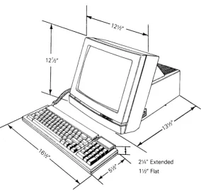
Figure 1-2 shows the WY-30 dimensions. The user should allow
three inches of clearance on all sides when installing the terminal.
Users can install the terminal near most other types of electrical
or electronic equipment without serious interference. They should
avoid locations near strong magnetic fields that can distort and interfere with the operating or servicing of the video display.
Figure 1-2 Terminal Dimensions
2%,' Extended
1 W' Flat
Ambient room temperature should never exceed
45
degrees Celsius(113 degrees Fahrenheit) when the terminal is on; however, the
terminal needs no special cooling. Users should make sure the
rear of the terminal has a free flow of air. They shouldn't set
OPERATOR INTERFACES
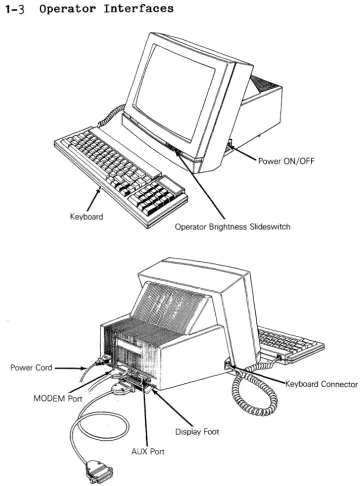
Figure 1-3 shows all operator interfaces, including the keyboard,
power cord, and brightness slideswitch. It also points out the
MODEM and AUX ports.
Figure 1-3 Operator Interfaces
Power ON/OFF
Keyboard
Power Cord --~.f'
Keyboard
Power Cord
Insert the power cord into the connection on the rear panel, and then plug the three-pronged connector into the AC power source.
Caution--Compare the voltage specified on the configuration label (on the back of the CRT enclosure) with the AC power source to avoid damaging the terminal.
Communications Cable
Connect the communications cable from the computer or modem to
the communications port labeled MODEM. This port defaults at
9600 baud, no parity, with one stop bit and eight data bits. The
operator can change these parameters in setup mode.
AC Power Switch
The power switch is on the right side of the terminal. Pressing
the back of the switch turns AC power on.
Brightness Slideswitch
The brightness slideswitch is located on the lower-right corner
of the front bezel. Sliding the switch to the right increases
the display brightness; sliding it to the left decreases the brightness.
Touch/Tilt Screen Adjustment
The touch/tilt screen adjustment is a spring-controlled support flap on the bottom of the terminal enclosure. A user can adjust the ang 1 e at which he v iews the screen by pushing or pu 11 ing the terminal bezel.
SETUP PARAMETERS
When a user turns the power on, the terminal executes an internal self-test. When the self-test finishes and the CRT is warm
(approximately 30 seconds), the cursor appears in the upper
left-hand corner of the display. The unit is now ready for
operation based on the setup parameters.
To inspect the parameters, press both the SHIFT and SETUP keys. The first level of parameters appears across the bottom of the
screen. To examine the other levels of parameters, press the
CURSOR DOWN key. Each time you press this key, you can see
To change the parameters, follow these steps:
1. Enter setup mode by pressing the SHIFT and SETUP keys.
2. Press CURSOR DOWN until the parameter to be changed is
displayed in the setup line, the row of highlighted fields at the bottom row of the screen.
3.
Press CURSOR RIGHT or LEFT until the specific parameter tobe changed is highlighted.
4.
Press the spacebar to advance the parameter to the specificsetting desired.
5. Press the cursor keys as required to advance to the next
parameter to be changed.
6.
To leave setup mode, press the SHIFT and SETUP keys.The status line flashes a message asking if the changed
parameters should be saved for power-on. Parameter changes
are implemented immediately.
Pressing the Y key saves the parameters that you keyed in.
Pressing the N key saves all changes temporarily. The new
parameters are effective only until you turn off the power.
Pressing the ESC key returns all parameters to their factory defau I t val ues.
Pressing the ENTER key restores all parameters from memory before leaving setup mode.
7.
To return to a normal operation mode, press any key.The terminal is now operational using the parameters defined in the setup mode.
See the WY-3D User's Guide for more comprehensive setup instructions.
CLEANING
You may find that the terminal needs to be cleaned when you've finish servicing it. The screen should be cleaned with a soft,
lint-free cloth. Apply a safe cleaner to the cloth, not directly
to the screen.
2 REMOVAL AND REPLACEMENT PROCEDURES
Overview
...
Before You Start Safety ... .. Required Tools
Removing and Replacing Assemblies Keyboard Module
in the
Keyboard
Keyboard Cable Keyboard PCB
Removing and Replacing Assemblies in Terminal Module ... .
Terminal Enclosure
the Fuse ... o e
the Terminal PCB
the CRT/Yoke Assembly Removing the
Replacing Replacing Replacing Replacing Replacing the Discharging
the Yoke . . . . Terminal Enclosure the Anode . . . .
the
2-2
2-2 2-2
2-3
2-3 2-3 2-4 2-5
OVERVIEW
This chapter explains how to remove and replace assemblies and
components in both terminal modules. For purposes of
orientation, "front" is the monitor face, and "back" is the rear panel and power cord location.
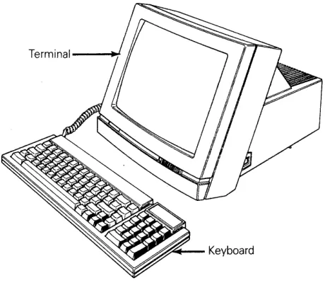
The terminal consists of two major modules (see Figure 2-1):
o
o
Terminal
Keyboard
The terminal module includes the CRT/yoke
assembly and the terminal PCB. The terminal
PCB holds all control logic, power supply circuitry, and the circuitry to amplify and display horizontal, vertical, and video signals on the CRT screen.
The keyboard module includes the keyboard PCB and the keyboard cable.
Figure 2-1 Terminal Modules
Terminal--~
.~'"+--Keyboard
BEFORE YOU START
Safety
Warning--This terminal contains high voltage. Don't attempt to
service the terminal without taking all the precautions necessary to work with high voltage, including the following:
o If you must open the terminal for any reason, turn off the
o Remove any jewelry, especially on hands and wrists.
o Avoid wearing clothing that holds a static charge.
o . Use only insulated or nonconductive tools.
o Whenever you disconnect the anode lead from the anode,
make sure to ground the anode as directed in "Discharging the Anode."
o If you need to remove or replace the CRT/yoke assembly,
remember that it can implode if you drop it or break the
neck. The flying glass can injure anyone within a radius of
six to ten feet.
Required Tools
Before you remove or replace any assemblies in the terminal, make sure you have the tools and materials listed below.
o No. 0 Phillips screwdriver
o No. 2 Phillips screwdriver
o Insulated flat-blade screwdriver
o Alligator clips
o Digital multimeter (or voltmeter)
o Nonscratch mat or surface
o Fuse puller or small flat-blade screwdriver
REMOVING AND REPLACING ASSEMBLIES IN THE KEYBOARD MODULE
This section describes procedures to remove and replace the keyboard, keyboard cable, and keyboard PCB.
Keyboard
Tools required: None
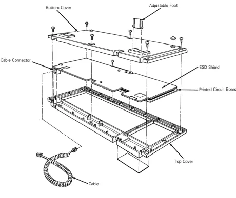
To replace the keyboard (see Figure 2-2), follow these steps:
1. Turn off the terminal.
2. Press the keyboard cable connector tab and pull the keyboard
cable out of the keyboard.
Figure 2-2 Keyboard Assembly
Bottom Cover
Cable Connector
ESD Shield
..dii1ii~---Printed Circuit Board
Top Cover
Cable
Keyboard Cable
Tools required: None
To replace the keyboard cable (see Figure 2-2), follow these
steps:
1. Turn the terminal off.
2. Press the keyboard cable connector tab and pull the keyboard
cable out of the keyboard.
3.
Press the other keyboard cable connector tab and pull thekeyboard cable out of the left side of the terminal.
4.
Insert one end of the new keyboard cable into the keyboardconnector. Insert the other end into the left side of the
Keyboard PCB
Tools required: No. 0 Phillips screwdriver
No. 2 Phillips screwdriver
To replace the keyboard PCB (see Figure 2-2), follow these steps:
1. Turn off the terminal.
2. Unplug the keyboard cable from the keyboard.
3.
Turn the keyboard over and remove the six No.2 Phillipsscrews that attach the keyboard bottom cover to the keyboard.
4.
Lift off the keyboard bottom cover.5. Remove the No. 0 Phillips screw beneath the spacebar
that holds the keyboard top cover to the PCB assembly.
6. Unscrew the three No. 0 Phillips screws and washers that
hold the keyboard ESD shield on the keyboard PCB.
7.
Lift the PCB assembly out of the keyboard cover.8. Cover the under side of the new keyboard PCB wi th the
keyboard ESD shield. Replace the screws and washers.
Tighten.
9. Fit the new keyboard PCB assembly back into the keyboard top
cover.
10. Replace the No. 0 Phillips screw that holds the PCB assembly
in place.
11. Reattach the bottom cover of the keyboard assembly.
12. Plug the keyboard cable back into the terminal.
REMOVING AND REPLACING ASSEMBLIES IN THE TERMINAL MODULE
This section describes removing and replacing the terminal
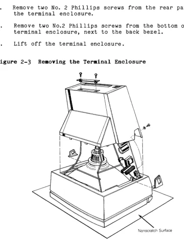
Removing the Terminal Enclosure
Tool required: No.2 Phillips screwdriver
To remove the terminal enclosure (see Figure 2-3), follow these steps:
1. Remove all cables and power cords from the rear of the
terminal.
2. Rest the display face of the terminal on a nonscratch
surface.
3. Disconnect the keyboard cable on the left side of the
terminal enclosure.
4.
Remove two No.2 Phillips screws from the rear panel ofthe terminal enclosure.
5. Remove two No.2 Phillips screws from the bottom of the
terminal enclosure, next to the back bezel.
6.
Lift off the terminal enclosure.Replacing the Fuse
Tool required: Fuse puller or screwdriver
The terminal has one fuse, rated 2 amps, 125 volts. See Figure
2-4
for the fuse location on the terminal PCB.To check or replace the fuse, follow these steps:
1. Remove the terminal enclosure.
2. Use a fuse puller to remove the suspected fuse.
3.
Check the fuse. If the fuse is broken or blackened, push anew fuse into the fuse socket.
If the fuse is good, push it back into the fuse socket.
4.
Replace the terminal enclosure (see "Replacing the TerminalEnclosure" for instructions).
Figure 2-4 Replacing the Fuse
Replacing the Terminal PCB
Tools required: No. 2 Phillips screwdriver
Flat-bladed screwdriver
Alligator clips
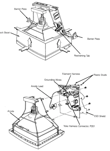
To remove the terminal PCB (see Figure 2-5), follow these steps:
1. Remove the terminal enclosure.
2. Slide the barrier plates mounted on either side of the back
bezel out from under the restraining tabs.
3. Leaving the terminal on its face, pull the back bezel off
the terminal chassis.
4. Discharge the anode (see "Discharging the Anode" for
instructions).
5. Disconnect the anode lead.
6. Disconnect the yoke harness connector, P201, from the
terminal PCB.
Warning--Handle the CRT neck carefully. If you break it,
flying glass can injure anyone within a radius of six to ten feet.
7. Disconnect the filament harness from the neck of the CRT.
8. Unscrew the ,two Phillips No.2 screws securing grounding
wires to the CRT chassis.
Caution--Don't remove the Phillips screws directly
underneath the rear panel on the terminal PCB. They fasten
the rear panel to the terminal PCB.
9. Remove the four plastic studs securing the ESD shield to the
back of the terminal PCB.
10. Loosen any screws holding the ESD shield in place.
11. Remove the ESD shield.
12. Loosen the six No.2 Phillips screws on the underside of the
terminal PCB.
Figure 2-5 Removing the Terminal PCB
Back Bezel
To replace the terminal PCB, follow these steps:
1. Position the ESD shield on the back of the terminal PCB.
2. Replace the four plastic studs that secure it.
3. Position the terminal PCB in its slot in the bezel. Make
sure the lever of the brightness potentiometer fits into the brightness slideswitch on the bezel.
4. Tighten the six screws that secure the terminal PCB to the
chassis.
5. Reconnect the grounding wires to the chassis.
6. Reconnect the yoke harness to P201 on the terminal PCB.
Warning--Handle the CRT neck carefully. If you break it,
flying glass can injure anyone within a radius of six to ten feet.
7~ Reconnect the filament harness to the CRT neck.
8. Discharge the anode on the CRT (see "Discharging the Anode."
9. Reconnect the anode lead.
10. Replace the back bezel and both barrier plates.
11. Replace the terminal enclosure and keyboard.
Replacing the CRT/Yoke Assembly
Tools required: No.2 Phillips screwdriver
Flat-bladed screwdriver
Alligator clips
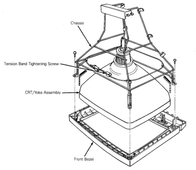
To remove the CRT/yoke assembly (see Figure 2-6), follow these steps:
1. Remove the terminal enclosure, keyboard cable, back bezel,
and barrier plates.
2. Remove the terminal PCB and insulation sheet.
3.
Unscrew the four No.2 Phillips screws securing the chassisto the front bezel.
Warning--Handle the CRT carefully. If you break it, flying
glass can injure anyone within a radius of six to ten feet.
Figure 2-6 Removing the CRT/Yoke Assembly
Tension Band Tightening Screw
CRT jYoke Assembly ----o.;~
To replace the CRT/yoke assembly, follow these steps:
1. Discharge the anode on the new CRT.
Warning--If you are replacing the same CRT/yoke assembly, you still need to discharge the anode. A CRT left standing for any length of time will develop a charge from the air, and need to be discharged again.
2. Place the assembly in the front bezel. Make sure the anode
faces the keyboard connector jack on the terminal PCB.
3.
Fit the chassis back into the bezel.4.
Replace the four No.2 Phillips screws that secure theassembly to the chassis. Tighten.
5. Replace the terminal PCB and insulator sheet.
6. Make sure the tension band is tight. If it isn't, tighten
7.
Replace the back bezel, barrier plates, and keyboard cable.8. Replace the terminal enclosure.
Replacing the Yoke
Tools required: None
To remove the yoke, follow these steps:
1. Remove the CRT/yoke assembly from the terminal.
2. Loosen the yoke lock on the neck of the CRT (see Figure 2-7).
3.
Remove the yoke.To replace the yoke, follow these steps:
Warning--Before you reattach the yoke assembly, you must
discharge the anode. A CRT left standing for any length of time
will develop a charge from the air, and need to be discharged again.
1. Position the yoke on the neck of the CRT (see Figure 2-7).
2. Tighten the yoke lock.
3.
Replace the CRT/yoke assembly in the terminal.Figure 2-7 Replacing the Yoke
Replacing the Terminal Enclosure
Tool required: No.2 Phillips screwdriver
To replace the terminal enclosure, follow these steps:
1. With the terminal face on a nonscratch surface, reseat the
enclosure over the chassis into the back bezel.
2. Replace the two No. 2 Phillips screws on the rear of the
terminal enclosure. Tighten.
3.
Replace the two No.2 Phillips screws on the bottom of theterminal. Tighten.
Discharging the Anode
Tools required: Insulated flat-blade screwdriver
Alligator clips
We have written specific warnings throughout this chapter about
discharging the anode on the side of the CRT. If you have never
discharged the anode, or need a review, follow these instructions.
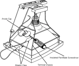
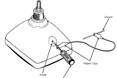
To discharge the CRT anode before removal (see Figure 2-8), follow these steps:
Figure 2-8 Discharging the Anode Before Removal
1. Turn off the terminal and unplug it from its power source.
2. Remove the terminal enclosure.
3.
Ground the shaft of an insulated flat-bladed screwdriver tothe terminal chassis with alligator clips.
4.
Slip the blade between the anode cap and the anode. Touchthe blade to the wire anode leads under the cap. Listen for
a popping or crackling sound.
5. Remove the anode lead.
To discharge the anode before installation (See Figure 2-9), follow these steps:
1. Ground the shaft of an insulated flate-bladed screwdriver.
2. Touch the blade of the screwdriver to the anode. Listen for
a popping or crackling sound.
3.
Install the CRT.Figure
2-9
Discharging the Anode Before Installation3 TROUBLESHOOTING
Before You Start Safety ... .
Required Tools
Troubleshooting Quick Reference Guide
Troubleshooting Flowchart
Troubleshooting
Installation Checking for
Aids ... .
Checklist Continuity Power Supply Check on the Power-On Self-Test
Diagnostic Self-Test Checking the Keyboard Isolating Circuits
Terminal PCB
3-2
3-2
3-2
3-3
3-3
BEFORE YOU START
Safety
Warning--This terminal contains high voltage. Don't attempt to
service the terminal without taking all the precautions necessary for working with high voltage, including the following:
o If you must open the terminal for any reason, turn off
the power, disconnect any communication cables, and unplug the terminal.
o Remove any jewelry, especially from your hands and wrists.
o Avoid wearing clothing that holds a static charge.
o Use only insulated or nonconductive tools.
o Whenever you disconnect the anode from the anode lead,
make sure to discharge the anode as directed in Chapter 2.
o If you need to remove or replace the CRT/yoke assembly,
remember that the CRT can implode if you drop it or break
the neck. The flying glass can injure anyone within a
radius of six to ten feet.
Required Tools
Before you start to repair in the terminal, make sure you ha ve the tools and materials listed below.
o No. 2 Phi 11 ips screwdri ver
o 3/16-inch flat-bladed screwdriver
o Digital multimeter (or an ohmmeter and voltmeter)
o Test connectors for the MODEM and AUX ports (See Appendix C
for instructions to make them or Chapter 5 for ordering
information.)
o Nonconductive video alignment tool
o Tie-wraps and clippers
TROUBLESHOOTING QUICK REFERENCE GUIDE
Table
3-1
is a troubleshooting reference guide. Once youdiscover the major symptoms, this table can quickly direct you to
the most likely problem area. However, don't automatically
replace the suggested modules until you've studied the problem or checked related details in the troubleshooting flowchart.
Table
3-1
Troubleshooting Quick Reference GuideSymptom Possible Problem Area(s)
No display Terminal PCB, CRT/yoke assembly
Poor display quality
Wrong size display Crooked
Too bright Not in focus
Fails self-test
Fails diagnostic test
Inoperative keys
Can't communicate with computer
Letters or error codes on the screen
Touch/tilt doesn't respond correctly
TROUBLESHOOTING FLOWCHART
Adjustments, terminal PCB
Adjustments, terminal PCB, yoke
Terminal PCB
Terminal PCB, wrong diagnostic setup, faulty test connectors
Keyboard, terminal PCB, keyboard cable
Setup parameters, terminal PCB, communication cable
Terminal PCB
Touch/tilt screw tension
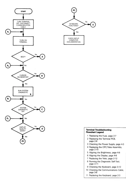
Read the troubleshooting flowchart and match the symptoms with
the suggested solutions. Any flowchart block that requires a
procedure includes a bold number that is keyed to the legend on
each page of the flowchart. The legend lists the procedure name
Figure
3-1
Troubleshooting Flowchart, page 1 of 4TURN TERMINAL OFF. DISCONNECT COMMUNICATION
CABLE
TURN ON TERMINAL
RUN SYSTEM DIAGNOSTIC
8
CHECK SETUP COMPUTER DOCUMENTATION
Terminal Troubleshooting Rowchart Legend
1 Replacing the Fuse, page 2-7 2 Replacing the Terminal PCB,
page 2-8
3 Checking the Power Supply, page 4-3 4 Replacing the CRT/Yoke Assembly,
page 2-10
5 Aligning the Brightness, page 4-8 6 Aligning the Display, page 4-6 7 Replacing the Yoke, page 2-12 8 Running the Diagnostic Self-Test.
page 3-11
9 Checking the Keyboard, page 3-12 10 Checking the Communications Cable,
page 3-8
Figure
3-1
Troubleshooting Flowchart, page 2 or 4CHECK FUSE
CHECK POWER SUPPLY
ADJUST
3
3
REPLACE FUSE
REPLACE TERMINAL PCB
REPLACE TERMINAL PCB
2
2
Terminal Troubleshooting Rowchart Legend
1 Replacing the Fuse, page 2-7 2 Replacing the Terminal PCB,
page 2-8
3 Checking the Power Supply, page 4-3 4 Replacing the CRT/Yoke Assembly,
page 2-10
5 Aligning the Brightness, page 4-8 6 Aligning the Display, page 4-6 7 Replacing the Yoke, page 2-12 8 Running the Diagnostic Self-Test.
page 3-11
9 Checking the Keyboard, page 3-12 10 Checking the Communications Cable,
page 3-8
Figure 3-1 Troubleshooting Flowchart, page 3 of 4
TURN OFF TERMINAL, REMOVE ENCLOSURE, TURN ON TERMINAL
PERFORM BRIGHTNESS ALIGNMENT
REPLACE TERMINAL PCB
5
2
Terminal Troubleshooting Flowchart Legend
1 Replacing the Fuse, page 2-7 2 Replacing the Terminal PCB,
page 2-8
REPLACE TERMINAL PCB
3 Checking the Power Supply, page 4-3 4 Replacing the CRT/Yoke Assembly,
page 2-10
5 Aligning the Brightness, page 4-8 6 Aligning the Display, page 4-6 7 Replacing the Yoke, page 2-12 8 Running the Diagnostic Self-Test,
page 3-11
9 Checking the Keyboard, page 3-12 10 Checking the Communications Cable,
page 3-8
11 Replacing the Keyboard, page 2-3
2
REPLACE TERMINAL PCB
PERFORM FULL MONITOR
ALIGNMENT
REPLACE TERMINAL PCB
6
2 2
REPLACE TUBE
4
REPLACE YOKE
Figure
3-1
Troubleshooting Flowchart, page 4 of 4PERFORM KEYBOARD
CHECK 9
CHECK COMMUNICATIONS
CABLE 10
CHECK HOST SOFTWARE
No REPLACE WITH
No
KNOWN GOOD KEYBOARD 11
REPLACE OLD KEYBOARD
REPLACE CABLE
No
REPLACE TERMINAL PCB
Terminal Troubleshooting Flowchart Legend
1 Replacing the Fuse, page 2-7
2 Replacing the Terminal PCB, page 2-8
3 Checking the Power Supply, page 4-3 4 Replacing the CRT/Yoke Assembly,
page 2-10
5 Aligning the Brightness, page 4-8 6 Aligning the Display, page 4-6 7 Replacing the Yoke, page 2-12
8 Running the Diagnostic Self-Test. page 3-11
9 Checking the Keyboard, page 3-12 10 Checking the Communications Cable,
page 3-8
TROUBLESHOOTING AIDS
This section contains a number of specialized procedures to help
you repair the terminal. Most of them are referenced on the
troubleshooting flowchart.
Installation Checklist
The checklist in Table 3-2 helps you quickly check terminal installation. If a user installs the terminal incorrectly, it
may not function properly. If you can't find the problem,
improper installation may be the key.
Table 3-2 Terminal Installation Checklist
Environment
Room temperature is between +40 and +91 degrees Fahrenheit (5 and 33 degrees Celsius).
Terminal isn't near a magnetic field.
Keyboard
Keyboard cable is in the keyboard connector jack on the left side of the terminal.
Keyboard cable is in the connector jack on the rear of the keyboard.
AC Power Cord
Female end of the power cord is pI ugged into the AC power socket on the rear panel of the terminal.
Male end of the power cord is plugged into the wall socket.
Communication Interface Cable
One end of the RS-232C interface cable is connected to the MODEM port on the terminal's rear panel.
Table 3-2 Continued
Computer Interface
You'll need to check the computer's documentation to determine the following information:
Correct baud rate
Correct stop bits
Correct data bits
Correct parity type
Correct handshaking protocol
Checking for Continuity
Sometimes you can fix the problem without opening the terminal.
The problem could be a damaged cable or power cord. Sometimes,
you may need to open the terminal to check the fuse or internal
connections. Check this list, then, with an ohmmeter, check the
continuity of the components listed below.
Outside the terminal, check the
o Power cord
o Communication cable (supplied with the computer)
Inside the terminal, check the
o Fuse
o AC power input receptac I e (on the rear panel of the
terminal)
o Terminal PCB to the CRT/yoke wiring harness
Hold the probes in place for five seconds, or until the ohmmeter
settles, to ensure an accurate reading. If the part in question
is open, replace it.
Power Supply Check on the Terminal PCB
Tools required: No. 2 Phi 11 ips screwdri v er Digital multimeter
Nonconductive video alignment tool
To check the voltages, follow these steps:
1. Turn the terminal off.
2. Remove the terminal enclosure.
3.
Attach one lead from the DMM to the chassis as ground.4.
Turn the terminal on.5. With the other lead from the DMM, look for these voltages at
these points on the terminal PCB:
Voltage
+5V .:t5%
+12V .:t5%
-12V .:t5%
Point
R15
C27
C31
6. If one or more of these voltages are not in tolerance,
adjust VR101.
7.
If you adjust VR101, and the voltage or voltages arestill not within tolerance, replace the terminal PCB.
Power-on Self-Test
The power-on self-test checks the terminal's random-access memory (RAM), read-only memory (ROM), electrically eraseable read-only memory (EEROM), and external communication ports.
Each time you turn the terminal on, the power-on self-test
occurs. If the test detects an error, an error message appears
on the display. Table
3-3
defines these error messages. If anyTable
3-3
Power-On Self-Test Error MessagesError
Message Failure
K EEROM checksum error
o
RAM errorX MODEM port TXD/RXD error
C MODEM port DTR/DCD error
A MODEM port RTS/CTS error
y AUX port error
9 EEROM read/write error
P PROM checksum error
Diagnostic Self-Test
The terminal diagnostic self-test routine starts in setup mode. This test routine includes communications circuitry tests,
read/write tests, and row buffer tests. Two special test
connectors allow the diagnostic test to function (see Appendix C
for connector definitions or Chapter 5 for ordering information).
After you start it, the diagnostic test continues to run until
you stop it. If the test detects an error, an error message
appears in the lower right-hand corner of the screen (see Table
3-4
for error message definitions).Follow these steps to start the diagnostic self-test:
1. Turn the terminal off.
2. Detach any communications cables on the back of the terminal.
3.
Attach the test connectors to the MODEM and AUX ports thatare on the rear panel of the terminal.
4.
5.
6.
7.
Note--See Appendix C for a description of these test connectors and instructions for making them.
Turn the terminal on.
Hold the SHIFT key, then press the SETUP key.
Press CURSOR DOWN five times. Look for to the TEST:OFF
field in the setup line at the bottom of the screen.
8.
Press the spacebar. This toggles the TEST field ON.9. Hold SHIFT, then press SETUP. Press~. You should see a
flashing test pattern.
10. Look for one of the error messages found in Table
3-4.
Note--To fully test the terminal, let the diagnostic self-test run five minutes.
11. If you see an error message, replace the terminal logic PCB;
if you don't see an error, press SETUP twice.
12. Turn the terminal off. Remove the test connectors, and
reattach the communications cables.
Table
3-4
Diagnostic Self-Test Error MessagesError
Message Failure
A RTS to CTS data communications error on MODEM port
C DTR to DCD data communications error on MODEM port
K EEROM data check sum error
o
RAM errorX Transmit/receive data error on MODEM port
Y Printer port error
9 EEROM read/write diagnostic self-test error
P Program ROM check sum error
Checking the Keyboard
If you suspect the keyboard is the source of the problem, follow this procedure to verify it:
1. Turn the terminal off.
2. Disconnect the communication cable.
3.
Connect pins 2 and3
on the MODEM port.4.
Turn the terminal on.5. The terminal should be in FDX (full-duplex) mode. (If it
6.
Type on the keys. Test all the keys in shifted andunshifted positions. If the keys don't respond, see section
E of "Troubleshooting Flowchart."
Isolating Circuits
If you troubleshoot to the component level using the schematics
in Chapter
7,
you may want to isolate the logic, monitor, orpower supply circuitry. Table 3-5 is a list of jumpers on the
terminal PCB and the areas they isolate~ For an exact location,
see the terminal PCB component layout in Chapter
5.
Table
3-5
Terminal PCB Circuit Isolation JumpersJumper Areas Isolated
J525 Ground from logic
J526
J524 Power supply from logic
J527
J543 Video circuit
Logic from monitor circuitry
J522 Vertical synchronization
Logic from monitor circuitry
J545 Horizontal synchronization
Logic from monitor circuitry
J725 Dim circuit
Logic from monitor circuitry
4 ADJUSTMENTS AND ALIGNMENTS
Before You Start Safety ...•.... Tools Required
Power Adjustments
Does the Terminal Meet the Display Specifications?
Aligning the Terminal Display
Adjustments Height
Vertical Hold Linearity Brightness Focus
Width ... . Display Leveling Display Magnets Centering Rings
4-2
4-2
4-2
4-3
4-4
4-6
4-7
4-7
4-7
4-8
4-8
4-9
4-9
4-9
BEFORE YOU START
Safety
Warning--This terminal contains high voltage. Don't attempt to
service the terminal without taking all the precautions necessary for working with high voltage, including the following:
o If you must open the terminal for any reason, turn off the
power, disconnect any communication cables, and unplug the terminal.
o Remove any jewelry, especially on your hands and wrists.
o Avoid wearing clothing that holds a static charge.
o Use only insulated or nonconductive tools.
o Whenever you disconnect the anode from the anode lead, make
sure to ground the anode as directed in Chapter 2, "Discharging the Anode."
o If you need to remove or replace the CRT/yoke assembly,
remember that it can implode if you drop it or break the
neck. The flying glass can injure anyone within a radius of
six to ten feet.
Tools Required
Before you test the power supply voltages or make any adjustments to the power supply or monitor assemblies, make sure you have the tools listed below.
o Flat-bladed nonconductive alignment tool
o Hex nonconductive alignment tool
o No. 2 Phillips screwdriver
o Digital voltmeter
o Oscilloscope
o Millimeter ruler or reticle (optional--see Appendix D for
instructions on how to use the reticle when you align the terminal display)
Note--Before you make any adjustments on the power supply or
monitor assembly, make sure to let the terminal warm-up for 30
POWER ADJUSTMENTS
The monitor/power supply PCB provides all of the voltages for the
logic (+5V, +12V, and -12V). You can adjust the +5 supply.
Note--You can find the locations of all components and test points referred to in this chapter in Figure 4-1.
Figure 4-1 Power Supply Component Layout
To adjust the power supply, follow these steps:
1. Turn the terminal off.
2. Unplug the power cord from the back of the terminal. If
communications cables are attached to the back of the terminal, detach those, too.
3.
Place the terminal on its face and remove the terminalenclosure and back bezel (see Chapter 2).
4.
Plug the terminal into an AC power source.5.
Turn the terminal on.6.
Check the +5V supply at R15 on the terminal PCB, using thechassis as ground.
Note--If you can't bring the +5V supply into tolerance, see Chapter 3, "Troubleshooting."
8. Check the -12V supply at C31 on the terminal PCB. The
digital voltmeter should read -12V (+5 percent). If the
-12V supply is not within tolerance after you have adjusted the +5 supply, see Chapter 3, "Troubleshooting."
9. Check the +12V supply at C27 on the terminal PCB. The
digital voltmeter should read +12V (+5 percent). If the
+12V supply is not within tolerance after you have adjusted the +5 supply, see Chapter 3, "Troubleshooting."
10. Turn the terminal so the screen is visible. Set the
terminal PCB on a surface where the traces will not touch other metal.
11. Check to see if the display needs alignment. (See "Does
the Terminal Meet the Display Specifications?") If it
doesn't need alignment, turn off the terminal, unplug it, and replace the top cover.
If the display needs alignment, go to "Aligning the Terminal Display."
DOES THE TERMINAL MEET THE DISPLAY SPECIFICATIONS?
Before you adjust the display on the monitor, measure the screen margins and study the display, following the procedure below.
Note--If you have just finished checking and adjusting the power
supplies, go to step 4.
1. Turn the terminal off.
2. Unplug the power cord from the back of the terminal.
3. If any communications cables are attached to the back of the
terminal, detach ,them.
4. Attach the test connectors to the MODEM and AUX ports on the
rear panel.
Note--See Appendix C for a description of these connectors
and instructions for making them. See Chapter 5 for
ordering information.
5. Plug in the power cord and turn the terminal on. Let it run
for 30 minutes.
Note--If you check the display before it runs for 30 minutes, your measurements may not be accurate.
6. Hold the SHIFT key, then press the SETUP key.
7.
Press CURSOR DOWN five times. Look for the TEST:OFFfield in the setup line at the bottom of the screen.
8. Press CURSOR RIGHT four times.
9. Press the spacebar. This toggles the TEST field ON.
10. Hold the CTRL key, then press the SETUP key. Press the N
key. You should see a flashing test pattern.
11. Hold down the spacebar until the test pattern stops
flashing.
12. Margins on the top, bottom, and both sides should measure
11mm (+2mm). If they don't, see the next section,
"AlignIng the Terminal Display."
13. Look at the display. Do you see any of these problems?
o Barreling (display edges that curve outwards)
o Pincushioning (display edges that curve inwards)
o Display edges aren't straight
o Display is too wide or too narrow
o Display is too high or too short
o Display isn't centered or level
o Poor focus
o Too dim or too bright
o Poor contrast
o Letters at the top of the pattern are a different size
than the letters the bottom
o Letters aren't uniform throughout
If you find any of the problems mentioned here, go to the next section, "Aligning the Terminal Display."
If the display is within specification and looks normal,
turn the terminal off. If the terminal was opened, you can
ALIGNING THE TERMINAL DISPLAY
Warning--The CRT/yoke assembly has high voltages. Only qualified
service personnel should perform these adjustments.
The monitor has several alignments and adjustments. If the
terminal display is out of tolerance in one or two areas, make
adjustments to correct only those problems. If you change the
CRT/yoke assembly or the terminal PCB, you must perform a full
alignment. Peform these procedures only if the display is out of
tolerance and doesn't match the specification.
Note--If you already have the test pattern on the screen, go to step 9.
To align the terminal display, follow these steps:
1. Turn the terminal off.
2. Disconnect the communications cables and power cord.
3. Attach the test connectors to the MODEM and AUX ports on the
rear pane 1.
Note--See Appendix C for a description of these connectors and instructions for making them.
4. Plug the power cord into the back of the terminal and turn
it on. Let it run for
30
minutes. (If it has already runfor
30
minutes, continue the procedure.)5. Hold the SHIFT key, then press the SETUP key.
6.
Press CURSOR DOWN five times. Look for the TEST:OFFfield in the setup line at the bottom of the screen.
7.
Press CURSOR RIGHT four times.8. Press the spacebar. This toggles the TEST field ON.
9.
Hold the CTRL key, then press the SETUP key. Press the Nkey. You should see a flashing test pattern.
10. Hold down the spacebar until the test pattern stops
flashing.
11. Adjust the display. Check Figure 4-1 for component
locations.
Note--If you finish both the power and display adjustments, and
Table 4-1 Display Problems and Adjustments
Display Problems
Letters at the top of the display aren't the same height as those at the bottom of the display
Fuzzy letters
Too bright; too dim; raster scan lines show; individual problems with or dim
Display too short or too tall
Too wide or too narrow
No vertical hold
Not centered
Not level
Pincushioning, barreling, crooked edges, corners sag or move out of specification
ADJUSTMENTS
Adjustments
Linearity
Focus
Brightness
Height
Width
Vertical hold
Centering rings
Yoke lock
Display magnets
Page
4-8
4-9
4-8
4-7
4-7
4-7
4-12
4-9
4-10
This section contains detailed instructions for each adjustment
mentioned in Table 4-1. Figure 4-2 can help you to identify
adjustment locations on the terminal PCB.
Height
The height adjustment is labeled VR302 on the terminal PCB. Adjust VR302 until the top edge and the bottom edge of the
display are both 11mm (~2mm) from the edge of the bezel.
Vertical Hold
Figure 4-2 Adjustment Locations
VR201, Focus
Linearity
The linearity adjustment is labeled VR303 on the terminal PCB. Adjust VR303 until characters on the bottom of the display are the same height as those on the top.
Brightness
You can adjust bright and dim separately. Although you can adjust them independently, it's a good idea to adjust bright first, and then dim.
1. Slide the brightness slideswith as far right as possible
(fu 11 brigh tness).
2. Turn VR202 on the terminal PCB as far clockwise as possible.
You should see the raster lines on the screen.
3. Slowly turn VR202 counterclockwise, just until the raster is
4.
Compare the full bright line-blocks in the test pattern tothe dim line-blocks in the test pattern. If dim looks
either too bright or not bright enough, adjust VR401 until the contrast looks correct.
Focus
Note--Do not use the focus control to adjust the outer
extremities of the screen. Some focus distortion happens in any
CRT.
The focus adjustment is labeled VR201 on the terminal PCB.
Adjust VR201 until the characters halfway between the center of the display and the bezel are distinct and clear.
Width
Caution--Do not use a metal tool to adjust the width coil. The magnetic properties of a metal tool will affect the adjustment.
The width adjustment is labeled L202 on the terminal PCB. With a
hex nonconductive alignment tool, adjust L202 until either side
of the display is 11mm (~2mm) from the edge of the bezel.
Display Leveling
The yoke lock is located on the neck of the CRT (see Figure 4-3).
To level the display, follow these steps:
1. Loosen the yoke lock on the neck of the CRT.
2. Rotate the yoke until the top and bottom edges of the
display are level with the top and bottom of the bezel.
3. Tighten the yoke lock.
Warning--Do not tighten the yoke lock too much or the neck of the
CRT will break causing the CRT to implode. The flying glass can
Figure
4-3
Yoke Lock on the CRT NeckRotate Yoke To Level Display
f
r""-~
=_::_
-,I - - - - __
'I
,
'I
,
I
I
II
, I
/ I
I
Yoke
Yoke Lock
Centering Ring Magnets
----
--
-
Display Magnets
There are eight display magnets on a ring around the yoke. When
turned, they change corresponding screen areas. They can also
affect adjacent areas. Figure 4-4 identifies each magnet; Table
4-2 identifies which portion of the screen each changes.
Figure 4-4 Display Magnets
Table 4-2
Magnet Number
1
2
3
4
5
6
7
8
7 3
5
Screen Areas Affected by Display Magnets
Area Affected
Top
Upper left corner
Left
Lower left corner
Bottom
Lower right corner
Right
Centering Rings
There are two display centering rings around the yoke. When
turned, they move the display position on the screen. Figure
4-5
shows the rings. If the display isn't in the center of the
screen, turn the rings until it is, then make height and width
adjustments described on pages
4-7
and4-9.
Figure
4-5
Centering Rings5 ILLUSTRATED PARTS LIST
Introduction . . . 5-2
Terminal Display Assembly Exploded View ...•...•.•...
5-3
Keyboard Assembly Exploded View ... 5-4
Terminal Components List ....•••.••..•••...•...•••••...• 5-5
Keyboard Components List ...••.•.•. 5-8
INTRODUCTION
This chapter provides the information you need to order parts for the terminal.
The first part of this chapter provides two exploded assembly
drawings: Figure 5-1, the terminal display, and Figure 5-2, the
keyboard. Each replaceable assembly, plastic covering, or cable
is labeled on the drawings with a specific part name and part
number. When you order replacement parts, please give both the
part name and the part number.
In the second part of this chapter, we list all piece parts, their values or generic industry numbers when relevant, and
locations on the terminal PCB or the keyboard PCB. Table 5-1
lists components on the terminal PCB. Table 5-2 lists components
on the keyboard PCB. Figure
5-3
is the terminal PCB componentFigure 5-1
Enclosure Assembly 830017-01
Back Bezel Assembly 830018-01
CRT (Tube) 640005-01
Terminal Display Assembly Exploded View
Barrier Plate, Power On/Off (AC Switch) 710049-01
Power Switch 340001-01
Figure 5-2 Keyboard Assembly Exploded View
Module Jack 560009-01
Keyboard Cable 94-038-03
I
I
~
...~
Keyboard Assembly 840013-01
Table 5-1 Terminal PCB Components List
Part Number Description
Integrated Circuits
230129-01 250220-01 80-300-02 80-400-00 80-400-04 80-400-09 80-400-11 80-400-15 80-400-24 80-400-26 80-400-27 80-400-29 80-400-34 80-400-64 80-430-04 80-431-12 80-431-34 80-431-40 80-432-00 80-432~01 80-432-15 80-432-20 80-432-23 80-435-12 80-520-10 Resistors 80-161-29 80-161-37 80-161-38 80-161-39 80-161-40 80-161-43 80-161-46 80-163-03 80-900-00 80-900-02 80-900-04 80-900-05 80-900-08 80-900-11 80-900-12 80-900-13 80-900-14 80-900-15 80-900-17 80-900-19
ASY FIRMWARE CHAR. GEN. PRO ASY FIRMWARE PROGRAM PROM PPT BEEPER,AUDIO
PPT Ie 74LSOO PPT IC 74LS04 PPT IC 74LS139 PPT IC 74LS174 PPT IC 74LS374 PPT IC 74LS132 PPT IC 74LS74 PPT IC 74LS283 PPT IC 74LS158 PPT IC 74LS138 PPT IC 74LS368
PPT IC 4016 2K x 8K STATIC RAM
PPT IC 2661-B
PPT IC CRT CNTL 6845RA 2MHZ PPT IC 68BOO MICROPROCESSOR PPT IC 1488
PPT Ie 1489
PPT IC ADJ. SHUNT REGULATOR PPT IC TDA 1170N
PPT IC 4N35
PPT IC GATE ARRAY (VIDEO) ER5911A 1024 BIT EEROM
PPT RES.,VAR.1K OHM PPT RES.,VAR.100K-B PPT RES.,VAR.100K-B PPT RES.,VAR.200K-B PPT RES.,VAR.2MEG-B PPT RES.,VAR.500 OHM PPT RES.,VAR.100K-A
PPT THERMISTOR SG-15 50HM 1A PPT RES, CF 100 OHM 1/4W 5% PPT RES, CF 470 OHM 1/4W 5% PPT RES, CF 680 OHM 1/4W 5% PPT RES, CF 1K OHM 1/4W 5%
PPT RES, CF 10K OHM 1/4W 5% PPT RES, CF 3.3 OHM 1/4W 5% PPT RES, CF 47 OHM 1/4W 5% PPT RES, CF 68 OHM 1/4W 5% PPT RES, CF 220 OHM 1/4W 5% PPT RES, CF 1.5K OHM 1/4W 5% PPT RES, CF 39K OHM 1/4W 5% PPT RES, CF 56K OHM 1/4W 5%
Table 5-1 Continued
Part Number Description Location
Resistors (continued)
BO-900-20 PPT RES, CF 6BK OHM 1/4W 5% R225,R309
BO-900-21 PPT RES, CF 150K OHM 1/4W 5% R21B,R303 BO-900-22 PPT RES, CF 270K OHM 1/4W 5% R304
BO-900-23 PPT RES, CF 470K OHM 1/4W 5% R306
BO-900-24 PPT RES, CF 12K OHM 1/4W 5% Rl0B
BO-900-31 PPT RES, CF 4.7K OHM 1/4W 5% Rl07,R12,R14 R15,R16
BO-900-33 PPT RES, CF 120K OHM 1/4W 5% R219
BO-900-35 PPT RES, CF lOOK OHM 1/4W 5% R214
BO-900-37 PPT RES, CF B2 OHM 1/4W 5% R313
BO-900-39 PPT RES, CF 2.2K OHM 1/4W 5% Rl0,Rll,R2,R9
BO-900-46 PPT RES, CF 22K OHM 1/4W 5% R220 BO-900-5B PPT RES, CF lMEG, 1/4W 5% R215
BO-900-65 PPT RES, CF 220K OHM 1/4W 5% R312 BO-900-69 PPT RES, CF 62 OHM 1/4W 5% R405
BO-900-B9 PPT RES, CF 15K OHM 1/4W 5% R 11 0
BO-900-90 PPT RES, CF 33 OHM 1/4W 5% Rl04,R5
BO-900-93 PPT RES, CF 10 OHM 1/4W 5% R22,R23,R24,R25
R26,R27,R2B,R29 BO-901-04 PPT RES, CF 57 OHM 1/4W 5% R202
80-901-50 PPT RES, CF lBOK OHM 1/4W 5% R302
BO-901-63 PPT RES, MOF 12 OHM 2W 5% R113 BO-901-69 PPT RES, WW 1.5 OHM 3W 5% R105
BO-901-71 PPT RES, MOF 1K OHM 2W 5% R40B
80-901-76 PPT RES, CF 330K 1W 5% R101
80-904-03 PPT RES, CF 120K OHM 1/2W 5% R114,R115
BO-904-15 PPT RES, CF 1 OHM 1/2W 5% R30B
80-904-42 PPT RES, CF 3K OHM 1/4W 5% R222
80-904-50 PPT RES, CF 10 OHM 1/2W 5% R224
BO-905-43 PPT RES, MOF 33 OHM lW 5% R102,R203
80-905-64 PPT RES, CF 220K OHM 1/2W 5% R216,R217
BO-905-66 PPT RES, MOF 560 OHM 1W 5% R204 BO-905-69 PPT RES, MOF 1K OHM 5W 5% R103
Crystals, Coils, Diodes, Transistors
410009-01 PPT COIL, HOR. WIDTH L202
410010-01 PPT COIL, HOR. LINERARITY L203
410011-01 PPT COIL, DYNAMIC FOCUS L204
BO-006-06 PPT COIL, 10UH CHOKE L104
80-170-01 PPT DIODE