University of
Twente
Faculty of Electrical Engineering,
Mathematics & Computer Science
Integrated Design and Implementation Tool
for Multi-Agent Controllers [IDITmac]
G. Bajracharya
MSc Thesis
Supervisors: prof. dr. ir. J. van Amerongen
March 2003
Report 001CE2003
Control Laboratory
Faculty of Electrical Engineering,
Mathematics & Computer Science
University of Twente
P. O. Box 217
7500 AE Enschede
The Netherlands
dr. ir. T.J.A. de Vries
Abstract
Multi-Agent Controller Systems (MACS) form a new concept in the field of control engineering. In the Multi-Agent Controller System framework, a complex control problem is divided into simple control problems and the solution to each of these problems is implemented as a controller agent. Controller Agents within MACS are coordinated with each other to solve the complex problem.
A specification language, MacsML (Multi-Agent Controller Specification Markup Language), has been developed for specifying MACS, which is based on XML (Extensive Markup Language) and on MACSL (Multi-Agent Controller Specification Language), a specification language for MACS that has been developed previously. A tool, IDITmac (Integrated Design and Implementation Tool for Multi-Agent Controllers), has been developed in this thesis, which supports checking of the specification and generation of C++ code of the specified MACS. The generated code can run in real system. A dll (dynamic link library) of the MACS can also be generated by this tool, which can then be used in 20-Sim for simulation purposes.
Contents
Preface ... v
1 Introduction... 1
1.1 Modern Control Solutions... 1
1.2 Integrated Design and Implementation Tool... 2
1.3 Multi Agent Controller... 2
1.4 Goals of the project ... 3
1.5 IDITmac ... 4
1.6 Outline of this thesis... 4
2 Background of the Project ... 7
2.1 Introduction... 7
2.2 Overview of Methodologies for Controllers ... 7
2.2.1 Control Architecture... 8
2.2.2 Agents Based Software Development ... 9
2.2.3 Code generation... 11
2.2.4 Controller specification ... 11
2.3 Integrated Approach for Controllers ... 12
2.3.1 Competent Specification of Multi Agent Controller ... 13
2.3.2 Support for Design of Multi Agent Controller ... 13
2.3.3 Integrated Implementation of Multi Agent Controller ... 13
2.4 Conclusion ... 15
3 Multi Agent Controller System Architecture... 17
3.1 Introduction... 17
3.2 Agent... 17
3.3 Multi Agent Controller System... 18
3.3.1 Overview of Multi-Agent Controller Implementation Framework (MACIF) ... 18
3.4 Architecture of Multi Agent Controller System... 22
3.4.1 Agent ... 23
3.4.2 Sensor Agent ... 24
3.4.3 Actuator Agent ... 24
3.4.4 Controller Agent... 24
3.4.5 Elementary Agent... 25
3.4.6 Composite Agent... 25
3.4.7 Coordination Object ... 26
3.4.8 Main Agent... 26
3.5 Conclusion ... 27
4 Specification of Multi Agent Controller System ... 29
4.1 Introduction... 29
4.2 Multi-Agent Controller Specification Language... 29
4.3 Multi-Agent Controller Specification Markup Language (MacsML). 30 4.3.1 XML Schema for MacsML ... 32
4.3.2 Basic Structure of MacsML ... 33
4.3.3 Input Ports and Output Ports ... 34
4.3.4 Parameters Definitions and States ... 35
4.3.5 Method Specification ... 35
4.3.6 Controller Agents within Composite or Main Agent ... 36
4.3.7 Coordination within Composite or Main Agent... 36
4.3.9 Including Header Files...37
4.3.10 Instances of C++ Classes ...37
4.4 Conclusion...38
5 Design and Implementation of Multi-Agent Controller Systems...39
5.1 Introduction ...39
5.2 Operating Principle of Multi Agent Controller Systems ...39
5.2.1 Multi-Agent Controller Systems and the Environment ...39
5.2.2 Main Agent ...40
5.2.3 Sensor Agent...42
5.2.4 Actuator Agent...42
5.2.5 Coordination Object...43
5.2.6 Composite Agent ...43
5.2.7 Elementary Agent ...44
5.2.8 Realization of Multi-Agent Control Systems ...45
5.3 Keywords...46
5.3.1 Ports, Parameters and State Variables types ...46
5.3.2 Sensor and Actuator types for 20-Sim...46
5.3.3 Operating State of Elementary Agents ...46
5.3.4 Keywords of Coordination Objects ...46
5.4 Design of Multi-Agent Controller Systems with 20-Sim ...48
5.5 Implementation of Multi-Agent Controller Systems with 20-Works..49
5.6 Conclusion...50
6 Case Study...51
6.1 Introduction ...51
6.2 Demonstration Setup (DemoLin) ...51
6.3 Control Problem ...52
6.4 Control Strategy...52
6.4.1 Sensor and Actuator Agents ...54
6.4.2 Motions of DemoLin ...54
6.4.3 PID-Controller and Safety ...56
6.5 Simulation Result ...56
6.5.1 Model of DemoLin ...56
6.6 Implementation Result...57
6.7 Conclusion...60
7 Conclusion and Recommendation...61
7.1 Conclusion...61
7.2 Recommendation...63
APPENDIX A XML and XML Schema ...65
A.1 Background of XML (Extensive Markup Language)...65
A.2 XML (Extensive Markup Language)...65
A.3 W3C XML Schema ...66
APPENDIX B UML...69
B.1 Structural Diagrams...69
B.1.1 Class Diagram...69
B.2 Behavior Diagrams ...70
B.2.1 Sequence Diagram ...70
B.2.2 Statechart Diagram ...71
APPENDIX C Features of IDITmac ...73
C.1 Support for MacsML in IDITmac ...74
C.2 Support for Design and Implementation in IDITmac...75
APPENDIX D DemoLin Setup and Model ...77
D.1 Configuration of DemoLin ...77
D.3 Model of DemoLin... 78
APPENDIX E Design of PID-Controller for DemoLin... 79
E.1 Plant Model ... 79
E.2 Design ... 80
E.3 Online Parameter Tuning ... 81
APPENDIX F Multi-Agent Controller System for DemoLin... 83
P
REFACE
Thanks are due to a lot of people for their encouragement and help in the completion of this project.
Firstly, I would like to express my gratitude to Theo de Vries, for his valuable guidance and continuous support during execution of this project. His suggestions and critical remarks were instrumental in the success of this thesis. I would like to thank Job van Amerongen for providing a warm welcome into the Control Group and for directing me towards finding a project suited to my interests. I would also like to thank Jan Broenink for his suggestions in the UML aspects of this project, and Bas de Kruif for his guidance in this project. I am grateful to Mark Verwoerd for his feedback regarding my report. A special thanks goes to Paul Weustink and CLP for his help for preparing the movie for the presentation.
The case study used in this project is implemented in DemoLin, a setup from Imotec BV. I am grateful to Imotec for providing me the facility to work on their setup.
C
HAPTER
1
1
I
NTRODUCTION
1.1
Modern Control Solutions
Needs of control engineers are growing with the advancement of technologies in the field of control engineering. Rapid advances in computational power introduce ability to solve even more complex control problems. Sophisticated systems have been successfully developed and implemented which exploit enormous computational power. Almost all present day controllers are being implemented with software realization to accomplish the increasing needs of the current problems. Hardware excellence in computer applications supplements functionality, flexibility as well as cost effectiveness of the computer based control solutions.
Soft solution approach to hard control problems of industrial environments has triggered evolution of automation in manufacturing processes. Present industrial controllers evolved from conventional loop control to hierarchical layered structures to supplement additional functionalities. Functions such as Sequence Control, Supervisory Control, Data logging and Interfaces with other plants, which used to be accomplished with human intelligence, are being implemented autonomously with the aid of computer supervision. Automation not only reduces production cost but also improves production efficiency by increasing production capacity and decreasing production time.
1.2
Integrated Design and Implementation Tool
In an industrial process, design of controllers involve formulation of reasonably accurate models of the plant to be controlled, designing control laws based on the derived models and simulating the designed control laws using available simulation tools. Whereas implementation is accomplished by converting the designed control laws to the native code of target systems, most commonly embedded microprocessor based architecture or personal computer with analog and digital interfaces. Controllers can be designed in the continuous, discrete or hybrid time domain whereas implementation is accomplished mostly in discrete time domain as most of the present day controllers are being implemented in digital machines. Presence of the vast difference in design and implementation of control applications is inherent due to different concepts in the field of control engineering and computer science. Thus, transformation of controller designs to implementation induces possibilities of errors and unreliable behaviors. In some cases, these errors cannot be identified by rigorous tests of the implementation thus these errors results in failure of the system causing serious and even catastrophic disaster.
Furthermore, a hierarchical layered control structure, which is essential in the industrial processes, is complicated to be simulated using present simulation tools for mechatronic systems. Features such as mode switching and state transition, which are often encountered in a control system, are difficult to capture in simulation tools and cannot be structured well. Being object oriented, these tools still cannot accommodate inheritance and polymorphism in the design, which is a key factor of successful and efficient implementation. The resulting implementation often tends to deviate from the designed controller, downgrading the performance of the controller.
The need for an integrated approach in the design and implementation of a controller for mechatronic systems is mandatory. This project is an effort to extend these well-proven tools for supporting not only the design aspect of mechatronic systems but also its implementation phases thus providing an integrated design and implementation environment, which, apart from facilitating the implementation of the design, reduces possible errors occurring in realizing the design and supplements functionality to the design itself.
1.3
Multi Agent Controller
multiple agents are acting on their particular problem to solve the complete complex problem, conflicts between individual agents arise, as these partial problems are interdependent. These conflicts are resolved by coordination between the agents.
Multi agent controllers are being implemented in solving control problems also. Van Breemen (2001) [23] has successfully implemented multi agent controllers in numerous control problems. Implementations presented also featured functionalities such as a hierarchical structure of controllers with multi-layered agents and efficient state transitions with ‘initialize’ and ‘finalize’ procedures. The framework incorporates bottom-up approach of design enabling incremental design of controllers. The ability of handling generic control problems is well suited for applying the framework of multi agent control in the integrated design and implementation of mechatronic systems. The structured framework of multi agent controllers can be exploited to ensure well-organized design and error free implementation.
1.4
Goals of the project
As mentioned earlier, the need for an integrated tool for design and implementation is inevitable for control system design, which supports the current developments in the field of controller design. Multi Agent Controller System has potential to implement advanced control systems, though an integrated support tool for Multi-Agent Controller System is still lacking. The main aim of this project is to develop and implement an integrated design and implementation tool based on Multi-Agent Controller System. The tool should be based on the Multi-Agent Controller Systems Implementation Framework (MACSIF) proposed by van Breemen (2001) [23]. The main task description of the project is summarized as follows.
Redesign of the specification tool of Multi-Agent Controller Systems to support efficient and extensible specification.
Build a design support tool, which can be used to test any designed Multi-Agent Controller System in a simulation environment.
Build an implementation support, which allows automated implementation of the designed Multi-Agent Controller System on real systems.
1.5 IDITmac
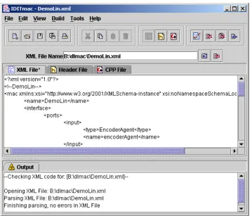
IDITmac (Integrated Design and Implementation Tool for multi-agent controller) is the software tool developed in this project to support an integrated approach for Multi-Agent Controller Systems. A snapshot of the graphical user interface of IDITmac is shown in Figure 1-1.
Figure 1-1: Snapshot of Graphical User Interface of IDITmac
IDITmac is developed in Java and it utilizes the Xerces 2 Java Parser [33] and the Microsoft Visual C++ Compiler. The tool supports XML editing, checking, generation of C++ code, generation of a dll (dynamic link library). The features of IDITmac are presented in Appendix C.
1.6
Outline of this thesis
Essential features of the implemented Multi-Agent Controller Systems are presented in this report. The organization of the report is as follows.
Chapter 3 describes the architecture of Multi-Agent Controller Systems. The description presented reflects the implemented system thus forms a basis for their specification. The architecture is presented in UML class diagrams.
Chapter 4 gives a brief description of MACSL (Multi-Agent Controller Specification Language), a specification language for Multi-Agent Controller Systems developed by van Breemen [23]. A guideline for the XML based specification developed in this thesis, MacsML (Multi-Agent Controller Specification Markup Language), is presented in the Chapter.
Chapter 5 introduces the operating principle and keywords of the implemented Multi-Agent Controller Systems. Frameworks for design and implementation of the integrated approach are presented in the chapter.
Chapter 6 presents a case study of Multi-Agent Controller Systems developed in this thesis to demonstrate the performance of the designed tool. The demonstration is supported by experiments performed on the case study.
C
HAPTER
2
2
B
ACKGROUND OF THE
P
ROJECT
2.1 Introduction
This chapter outlines the background of the project. The chapter describes current research trends in the field of controller architectures and agent based systems, currently available code generators and current trends of controller specification. A brief description of developments in controller architectures is presented with the focus in Mechatronic Systems. A study of agent based systems in the field of software development and control engineering is presented with examples of current applications of agents in control engineering. Current trends in automated code generation and controller specification are also studied. From the findings of current developments, an integrated approach of design and implementation of Multi-Agent Controller Systems is formulated. The integrated approach for controller is implemented in the project.
2.2
Overview of Methodologies for Controllers
This project covers four developments in four major fields and unifies these developments and implements it to solve control problems of mechatronic systems. The four developments are listed below:
Control Architecture
Agents Based Software Development Code Generation
Controller Specification
Current developments in above mentioned fields are narrated as follows.
2.2.1 Control
Architecture
The conventional controller design framework mainly focuses upon designing a single-loop controller for a plant. In this framework, the single controller is designed based on a single dynamic model of the plant. The general structure of conventional controllers is shown in Figure 2-1.
Controller
Act
uato
rs
Plant
Se
ns
ors
Conventional Control Architecture
Figure 2-1: General structure for feedback controllers
However, modern mechatronic systems are becoming increasingly complex, such as manufacturing processes, power plants etc. A single dynamic model and a single loop controller solution for such a complex system is often becoming the bottleneck in the modern control application. Most of the modern plants can be described conveniently by multiple models, consisting of (simple) submodels that describe the plant’s dynamic behavior in particular local regimes of the plant’s overall operating regime [1] [2]. Various design tools based on operating regime decomposition are available for designing controllers, such as ORBIT (Operation Regime Based modeling and Identification Toolkit for Matlab) [1].
Further, to simplify control problems, hierarchical control architectures are also proposed. In hierarchical control architectures, higher levels utilize coarser models of the system and lower levels deal with detailed models of the system. Several hierarchical models such as two-layered control hierarchy [5] [6], Open Control Platform with three-layered hierarchy [7] has been proposed.
Hierarchical structure is inherent in the controller structure of industrial processes. As illustrated in Figure 2-2, a seven-layered hierarchical structure is widely implemented in the industrial applications. Two base layers, Measurement and Actuation and Data Processing, are responsible for data acquisition and actuation. Loop controllers are generally feedback loop controllers and in special cases feedforward, adaptive controllers or other special controller algorithms. Generally, an industrial automation is complex to be controlled with a single loop controller. Coordination and sequencing of multiple loop controllers is done by sequence control, also known as logic control. Supervision of the operation of the controlled processes and data logging of the performance of the plant is also maintained. Further, a network interface is provided, which enables exchange of information between the controlled plants and Human Machine Interface (HMI).
2.2.2
Agents Based Software Development
An Agent is commonly used in software engineering and artificial intelligence as entity/program that are responsible for performing a set of tasks in coordination with its environment. Agents have been widely used in different contexts, ranging from generic autonomous agents, software agents and intelligent agents to the more specific interface agents, virtual agents, information agents, mobile agents and so on [8]. A definition of an autonomous agent by Franklin and Graesser (1997) is as follows [9].
“An autonomous agent is a system situated within and a part of an environment that senses that environment and acts on it, over time, in pursuit of its own agenda and so as to effect what it senses in the future.”
In the field of control engineering also, autonomous agents are being implemented to solve various control problems [10] [11] [12] [13] [15]. Autonomous controller agents sense their environment, i.e. the plant, by sensors and react to the environment through actuators, to obtain a desirable performance. The ability of agents to execute their tasks in coordination with other agents make them highly effective for structuring distributed control architectures and hierarchical control systems.
top. Bussmann and Schild (2001) [17] implemented agents in a modern automotive industry using work-piece agents, machine agents and switch agents. The work-piece agents auction off their current task, while the machine agents bid for the tasks and the switch agent coordinates the work-piece and machine agents.
Actu
ato
rs
Plant
Se
ns
ors
Network Interface Data Logging Supervisory Control
Sequence Control Loop Control Data Processing Measurement and Actuation
Discreet Time Transformation Continuous Time Physical System Interfaces
Industrial Controller
Figure 2-2: Hierarchical Structure of Industrial Controllers
Holonic Manufacturing Systems (HMS) [14] introduced a special type of physical agent called a “holons”, which consists of an information processing part and often a physical processing part, to provide an open environment for the manufacture of high-variety low-volume products. “Holons” is derived from the Greek word holos (signifying whole) with a suffix on (a particle, as in proton or neutron). Problem solving in an HMS is achieved by holarchies, or groups of autonomous and cooperative basic holons and/or recursive holons that are themselves holarchies [18].
Winner-takes-all, Sequential, Addition have been described. Further, the external interface of a controller agency is the same as that of a controller agent, which allows multiple layered hierarchical structures of controller agencies and controller agents. The given framework is being implemented on various applications such as a Water Vessel Problem [19], Room Thermostat Control [20], Process of Corrugated Cardboard [22], Fast Component Mounter [23] and so on.
2.2.3 Code
generation
Use of computer tools for design of control systems has been increasing in recent decades. Presently, various tools are available for computer aided control system design (CACSD) [24]. Some of the tools not only support analysis and design of controllers but also support automated code generation of the designed controllers for various target systems. Matlab [25] implements Real Time Workshop Embedded Coder and Stateflow Coder to generate C code directly from Real Time Workshop and Stateflow diagrams. Products such as dSpace [26] have been used for implementing code generated from Real Time Workshop and Stateflow diagrams. Software like MATX/RTMATX [27] also supports design of controllers and automated code generation from the designed controller. LabView [28] introduces hardware such as LabView Real-Time Model and RT series hardware targets, which can run applications, designed in LabView. Sim [29] also generates ANSI C code of Sim-models or 20-Sim-submodels that can be used in various systems. Standard templates are available to generate code for various applications. User defined templates can also be included to support customized code generation for a broad range of tasks.
20-Sim also supports linking during simulation through dll (Dynamic Link Library). The implementation of a control algorithm can be linked with 20-Sim through dll-functions to test the implementation.
2.2.4 Controller
specification
Specifications of loop controllers are mostly presented by equations and graphical representations. The specification provides information of data flow and state transitions of the controller.
independent. PNML has been implemented in industrial logic controller specification and design [31].
IEC 61499 Function Block is a component based open architecture, for Distributed Industrial-Process Measurement and Control Systems (IPMCS). IEC 61499 is derived from PLC Function Blocks (IEC 61131-3) and DCS Function Blocks (IEC 61804). A standard for XML based specification of IEC 61499 Function Block is also being developed [32].
For the multi agent controller framework of van Breemen (2001), an organizational diagram has been proposed for illustrating hierarchical structure of the agents[23]. However, the organizational diagram does not provide complete information of the agents, as data transfer between agents is not specified in the organizational diagram. The complete controller specification (which also includes the hierarchical structure) is defined in a specific text format.
2.3
Integrated Approach for Controllers
As illustrated in the previous section, various developments in different fields of control engineering are emerging to support the present needs of the controllers. Significant developments in the field of controller architectures provide sufficient support to simplify the design of complex control systems. The multi agent controller approach provides a backbone for implementing the available controller architectures in an effective and well-organized fashion. The framework of multi agent controller [23] accords hierarchical structuring of controllers, hybrid control systems with state transition and operating regime philosophy with mode switching. Controller specification and code generation from the specification ensure an error free and consistent implementation of the designed controllers.
2.3.1
Competent Specification of Multi Agent Controller
In the multi agent controller framework, multi agent controllers are coordinated with each other and their environment to solve a given control problem. In order to design a good controller, the specification of the controller should be precise and well structured.
The specification language for multi agent controllers is defined in an XML (Extensible Markup Language) format. A guideline for the specification is designed, which specifies the structure of the XML specification. The guideline is implemented as W3C XML Schemas [34] and the controller specification is validated against the Schemas to check the integrity of the specification.
2.3.2
Support for Design of Multi Agent Controller
Design tools such as 20-Sim are commonly used for designing mechatronic controllers. 20-Sim is a Windows-based simulation program for dynamic systems. 20-Sim also supports run-time linking of simulation with a dynamic link library module. The specified multi agent controller is simulated in 20-Sim with a dynamic link library. 20-Sim is a powerful modeling tool for multi-domain systems as it also supports bond graphs and iconic diagrams.
A library is built in the Microsoft Visual C++ to capture the generic behavior of multi agent controllers. From the specification of the multi agent controller defined in XML, C++ code is generated. The generated code is compiled and linked to generate a dynamic link library module using the Microsoft Visual C++ compiler and linker. The generated dll (dynamic link library) can be linked with 20-Sim to simulate the defined Multi-Agent Controller. The process of translation of the specification of the controllers in XML to C++ code and generations of the dll from the C++ code is automated by a software tool developed in java.
2.3.3
Integrated Implementation of Multi Agent Controller
The implementation of Multi-Agent Controller Systems is accomplished in 20-Works. 20-Works is a C++ (GNU compiler) based platform designed for control of mechatronic systems at Control Laboratory, University of Twente. 20-Works operates in a fixed sampling period. It also provides a graphical user interface and online plotting facilities.
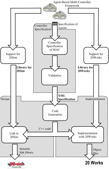
Controller Specification of MAC
Code Generation
Implementation with 20Works Link to
20Sim
Validation
Agent-Based Multi-Controller Framework
Object files Controller
Specification
XML Specification
Specification of Agents
dynamic link library
Support for 20Works Support for
20Sim
20 Works
Implementation Design
Library for 20Works Library for
20Sim
C++ code
2.4 Conclusion
In this section, current trends in controller design have been studied. Need of a tool for structuring the control strategy and providing an integrated approach in design and implementation of a control system to facilitate the current developments has been identified. Competence of Multi-Agent Controller Systems in organizing the control strategy has been demonstrated. Generic characteristics of Multi-Agent Controller Systems enable their application in almost all types of control systems. The flexible hierarchical structure of Multi-Agent Controller Systems facilitates appropriate structuring of the control solutions.
C
HAPTER
3
3
M
ULTI
A
GENT
C
ONTROLLER
S
YSTEM
A
RCHITECTURE
3.1 Introduction
This chapter gives the basic theory underlying Multi-Agent Controller Systems. A general description of an agent is presented and an introduction of the Multi-Agent Controller Implementation Framework developed by van Breemen (2001) [23] is presented. The architecture of Multi-Agent Controller Systems implemented in the project is presented with the aid of UML (Unified Markup Language), which is also a basis for Specification of Multi-Agent Controller System (Chapter 4). The operating principle of a Multi-Agent System is presented in Chapter 5.2-Operating Principle of Multi Agent Controller System.
3.2 Agent
Recently, the term “agent” is widely used in various fields of software engineering. In general, “agent” is termed as an autonomous entity responsible for performing a certain task in coordination with its community. Since the term “agent” is used very frequently in various fields with different purposes, a unanimous definition of the term “agent” cannot be formulated. However, an agent in general can be described as a system, which exhibits the following properties.
Autonomous: an agent is an intelligent entity that can act upon its local task independently without the assistance from other systems.
Social ability: an agent communicates with its environment (which may be a community of other agents and/or the physical environment of the whole system) to achieve the global objective (of the whole system).
The agent concept is not an absolute theory, which has a minimum requirement or a precise guideline that has to be followed to qualify for being an agent. The agent concept is a way of solving problems by dividing the solution of a complex problem into many autonomous and well-structured solutions and coordinating the well-structured solutions to achieve the goal. An agent should have a well-defined task description and should be able to perform its task by communicating with other agents and/or the physical environment.
Agents are extensively implemented in the field of artificial intelligence and distributed computing because of their autonomous and social ability. The configuration of the agents being implemented in these fields varies according to the problem to be solved and the approach taken to solve the given problem. However, the basic principles of the agents comply with the properties mentioned above.
3.3
Multi Agent Controller System
Apart from the field of artificial intelligence and the field of distributed computing, agent-based approach is being applied in control systems design also. Numerous control applications based on agents have been successfully developed and implemented [10] [11] [12] [13] [14] [15]. The architecture of the implementation of agents varies depending upon the problem description and the solution approach. However, the basic principle of autonomous agents with ability of communication is elemental in almost all the implementations.
A framework for implementing the agent-based concept in control engineering is proposed by van Breemen (2001) [23]. The “Multi-Agent Controller Implementation Framework” (MACIF) presents a generic backbone for implementing controllers as agents. The framework introduces controller agents, which can be integrated and coordinated efficiently to solve complex control problems [23]. The controller agents can be tailored to implement required controllers. The framework also presents a guideline for implementing these controller agents for solving general control problems.
The tool, “Multi-Agent Controller”, for the “Integrated Design and Implementation Tool”, developed in this project, is based on the “Multi-Agent Controller Implementation Framework” (MACIF). An overview of the Framework is presented in next section.
3.3.1 Overview of Multi-Agent Controller Implementation
Framework (MACIF)
signals as outputs. A Multi-Agent Controller consists of a single agent called “main agent” which constitutes different agents for reading input data (sensors and references), processing the input data (control algorithm) and outputting the actuation signal (actuators). The agents within the “main agent” are responsible for its local tasks and control the plant via communicating among each other. Six different primary components constitute the building blocks of the MACIF. These six agents are described briefly as follows.
Components
Sensor Agent: acquires data from the environment and dispatches the data to other agents. The environment involves the plant to be controlled and other external systems such as Human Interfaces (which gives references) or disturbances. In the discrete time implementation, Sensor Agents acquire these data from AD-converters (which acquire data from the environment).
Actuator Agent: dispatches the processed data to the environment. In the discrete time implementation, Actuator Agents dispatch data to DA-converters.
Composite Agent: consists of a group of Controller Agents (i.e. Elementary Agents and/or other Composite Agents) and a Coordination Object. Composite Agents enable layered structures of agents, as a Composite Agent may contain other Composite Agents.
Main Agent (Multi-Agent Controller): is the overall agent responsible for the whole control system. Main Agent is a kind of a Composite Agent so it consists of a group of Controller Agents and a Coordination Object. In addition, Main Agent also consists of a group of Sensor Agents and Actuator Agents, which interface with the environment. Main Agent is literally the main agent of a Multi-Agent Controller System. The Main Agent gets information of the plant to be controlled by its Sensor Agents and acts upon the plant via its Actuator Agents. A Multi-Agent Controller System has only one Main Agent, which is responsible for interfacing with the physical system (the controlled plant).
Coordination Object: is contained in all Composite Agents (and Main Agents). The task of a Coordination Object is to coordinate the behavior of the Controller Agents that exist within a Composite Agent (or a Main Agent).
Elementary Agent: is the fundamental agent of the MACIF and it implements local control solutions of the global control problem.
(“CA1”) is a Composite Agent. “MA1” also comprises a Coordination Object “CO1”, which coordinates the Controller Agents of “MA1” (i.e. “EA1” and “CA1”).
The Composite Agent “CA1” has three Controller Agents (“EA2-1”, “EA2-2” and “EA2-3”). All the three Controller Agents of “CA1” are Elementary Agents. In addition, “CA1” has a Coordination Object “CO2” which coordinates the Controller Agents (“EA2-1”, “EA2-2” and “EA2-3”) of the Composite Agent “CA1”.
These six types of components form basic building blocks of a Multi-Agent Controller System. Composite Agents allow for a hierarchical structure of the Multi-Agent Controller System and Coordination Objects allow for proper coordination (activation) of the sub-agents within a Composite Agent (Main Agent). Within a Composite Agent, data transfer between its sub-Agents and data transfer from its sub-Agents to its external (input/output) ports takes place via connections. Connections recommended by the MACIF are as follows.
Connections
OI Connection: (Output to Input Connection). OI Connection is a channel for data transfer from an Output Port of a agent to an Input Port of another sub-agent within a Composite Agent or a Main Agent.
EII Connection: (External Input to Input Connection). In a Composite Agent, an External Input Port is the Input Port of the Composite Agent. The data transfer channel from the External Input Port of the Composite Agent to an Input Port of one of the sub-agents of the Composite Agent is termed as EII Connection.
OEO Connection: (Output to External Output Connection). A connection from an Output port of one of the sub-agents of a Composite Agent to an External Output Port of the Composite Agent is termed as OEO Connection.
CA EA MA
AA SA
MA1
EA1
CA1
EA2-2
EA2-3
CO1 MA1
AA1
SA2
CO2 CA1
EA2-1
AA2 SA1
CO
Main Agent
Elementary Agent
Composite Agent
Coordination Object
Sensor Agent
Actuator Agent
External Input Port
External Output Port
Output-Input Connection
External Input-Input Connection
OI
EII
OEO OI
EII
OEO EII
OI OI
OI
OI OI
OI
Output-External Output Connection
Input Port
Output Port
As indicated above, direct connections between the ports of a sub-Agent of a Composite Agent and the ports of a sub-Agent of another Composite Agent is not allowed. Any such connection should be accomplished through external ports of the corresponding Composite Agents.
Output/ External Input (Source)
Input/
External Output (Destination)
Figure 3-2: Multiple Source connected to single destination
In all the connections, the data types of the connecting ports should be the same. In addition, conflict situations may arise due to combinations of connections, which result in multiple source and single (or multiple) destination of the data (see Figure 3-2). For EII connections and OI connections, such ambiguous situations are prohibited. For OEO connections, coordination object coordinates OEO connections and decides the active connection (active source). The active connection changes dynamically according to the operating conditions (see Section 5.3.4).
3.4
Architecture of Multi Agent Controller System
The “Multi-Agent Controller Implementation Framework” consists of the six fundamental components, namely Sensor Agent, Actuator Agent, Composite Agent, Main Agent, Coordination Object and Elementary Agent. Based on the features of these components, the components can be categorized in a hierarchical structure as shown in the UML (United Markup Language) class diagram (Figure 3-3). A description of UML is presented in Appendix B.
Elementary_Agent
Controller_Agent Actuator_Agent
Coordination_Object Agent
Main_Multi_Agent_Controller Sensor_Agent
Composite_Agent
Figure 3-3: Generalization (inheritance) of Components of Multi-Agent System (UML class diagram)
The six fundamental components of the Multi-Agent Controller can be described in terms of the classification presented in Figure 3-3. Description of the classification is presented in a top-down approach. Higher classes (or categories) are presented beforehand. Sub classes inherit the architecture of their super class, so the features, already presented in their super class, are not reiterated in the sub classes.
3.4.1 Agent
An Agent is a generic component of the Multi-Agent Controller System. The architecture of an Agent is illustrated in Figure 3-4. An Agent has a name field (of string type), which identifies the agent. It also consists of a set of ‘Input Ports’ and a set of ‘Output Ports’. ‘Input Port’ imports data from other agents whereas ‘Output Port’ exports data to other agents. Agents also have ‘Parameters’. ‘Parameters’ are variables, which can be initialized while creating (instantiating) an Agent.
-name : string +start():void +stop():void
contains
1 *
contians 1
* contains 1
*
* contains
1
Output_Port Agent
Parameter
Input_Port
State
Sensor_Agent Actuator_Agent
Figure 3-4: Architecture of Agent (UML class diagram)
3.4.2 Sensor Agent
Sensor Agent is one of the base components of the Multi-Agent Controller System. Sensor Agent specializes its super class, Agent, and has an additional method ‘sense():void’. The ‘sense():void’ method acquires data from AD-Converter (or the environment). The architecture of Sensor Agent is shown in Figure 3-5(a).
3.4.3 Actuator Agent
Actuator Agent is a base component of the Multi-Agent Controller System and is a kind of Agent. Actuator Agent has an additional method ‘actuate():void’. The ‘actuate():void’ method transfers data to DA-Converter (or the environment). The architecture of Actuator Agent is shown in Figure 3-5 (b).
+sense():void +actuate():void
(a) (b) Figure 3-5: Architecture of (a) Sensor Agent (b) Actuator Agent
(UML class diagram)
3.4.4 Controller Agent
no arguments and a return type of ‘real’. The ‘activation():real’ method processes the activation request of the Controller Agent and returns the degree of activation of the Controller Agent. The degree of activation ranges from 0 to 1, 0 indicating the Controller Agent wants to be inactive. The ‘acknowledge(boolean ack):void’ method receives acknowledgement of the activation request. The Controller Agent is activated if ack is true. The architecture of Controller Agent is shown below.
+operating_state : boolean
+acknowledge(boolean ack):void +activation():real
Controller_Agent
Elem entary_Agent
Figure 3-6: Architecture of Controller Agent (UML class diagram)
3.4.5 Elementary
Agent
Elementary Agent is one of the base components of the Multi-Agent Controller System. Elementary Agent is a kind of Controller Agent hence inherits all the features of Controller Agent. In addition, Controller Agent has four methods ‘initialize():void’, ‘finalize():void’, calculate():void’ and ‘update():void’. The ‘initialize():void’ method is executed when an inactive Elementary Agent becomes active and the ‘finalize():void’ method is executed when an active Elementary Agent becomes inactive. The ‘calculate():void’ method is executed when the Elementary Agent is active and it performs the necessary calculation of an active Elementary Agent. The ‘update():void’ method is executed both in active and inactive state of the Elementary Agent and it normally updates the ‘State’s of the Elementary Agent. The architecture of Elementary Agent is illustrated below.
+initialize():void +finalize():void +calculate():void +update():void
Figure 3-7: Architecture of Elementary Agent (UML class diagram)
3.4.6 Composite
Agent
*
contains 1 1 contains 1
* * *
1 1 1
1 *
coordinates
Coordination_Object Controller_Agent
Com pos ite_Agent
EII_Connection OEO_Connection OI_Connection
Coordination_Object
Figure 3-8: Architecture of Composite Agent (UML class diagram)
3.4.7 Coordination Object
Coordination Object is also one of the base components of the Multi-Agent Controller System. Apart from the inherited behaviors from its super class, Agent, Coordination Object consists of three additional methods ‘resolute():real’, ‘decide(boolean ack):void’ and ‘combine():void’. Coordination Object exists within a Composite Agent (and also in a Main Agent) as illustrated in Figure 3-8. The ‘resolute():real’ method processes activation requests of Controller Agents (sub Agents) of the Composite Agents (or the Main Agent) and returns the degree of activation of the Composite Agent (or the Main Agent). The ‘decide(boolean ack):void’ decides upon the activation of the Controller Agents (sub Agents) of the Composite Agent (or the Main Agent). The ‘combine()’ method combines the output of the Controller Agents. The architecture of Coordination Object is presented in Figure 3-9.
+resolute():real
+decide(boolean ack):void +combine():void
Figure 3-9: Architecture of Coordination Agent (UML class diagram)
3.4.8 Main
Agent
sampling instant of the Multi-Agent Controller System. The architecture of Main Agent is illustrated below.
+tick():void
its Sens ors 1 *
its Actuators
1 *
Main_Agent
Actuator_Agent Sens or_Agent
Figure 3-10: Architecture of Main Agent (UML class diagram)
3.5 Conclusion
An introduction of Multi-Agent Controller Systems as implemented in this thesis has been presented in this section. The architecture of the Agents has been presented, which forms a basis for the specification of Multi-Agent Controller Systems. The architecture of Agents has been structured in a hierarchical order and has been presented in UML notations, which forms a formal documentation of the Agents.
C
HAPTER
4
4
S
PECIFICATION OF
M
ULTI
A
GENT
C
ONTROLLER
S
YSTEM
4.1 Introduction
A specification language for Multi-Agent Controller Systems has been developed in this project. The specification language is named as Multi-Agent Controller Specification Markup Language (MacsML). MacsML is based on Extensive Markup Language (XML). A brief description of MacsML is presented in this chapter. The structure of MacsML is defined in XML Schemas and a brief introduction of the Schemas developed is presented in this chapter.
A brief introduction of another specification language, Multi-Agent Controller Specification Language (MACL), developed in van Breemen (2001) [23], is also presented in this section. In addition, an introduction to the tools support by IDITmac (tool developed in this project) for MacsML is also presented.
4.2
Multi-Agent Controller Specification Language
Multi-Agent Controller Specification Language (MACSL) is a specification language for Multi-Agent Controller recommended by van Breemen (2001) [23]. The specification of a Multi-Agent Controller System is described in a specific format in a text file. The six base components of Multi-Agent Controller Systems are defined by six different keywords namely, ‘sensor’, ‘actuator’, ‘cagent’, ‘coordination’, ‘mac’ and ‘cagency’. Van Breemen (2001) [23] also describes a set of keywords, which can be used in the specification.
Elementary Agent: PController
PController control_signal reference
measurement
inputs real reference;
real measurement;
outputs real control_signal;
parameters real kp=1.0;
calculate():void {
control_signal
=kp*(reference-measurement); }
Figure 4-1: Schematic representation of an Elementary Agent, PController MACL specification the P-Controller is presented in Table 4-1. The specification is in a plain text format though boldface typesetting is used to highlight keywords of MACL.
Table 4-1: An Example of MACL (specification of the P-Controller in Figure 4-1)
PController.msf cagent PController;
/*Specification of a MACS implementation of P-Controller in MACSL*/
inputs
real reference;
real measurement;
outputs
real control_signal;
parameters
real kp=1.0;
calculate {
control_signal=kp*(reference-measurement); }
end;
4.3
Multi-Agent Controller Specification Markup
Language (MacsML)
Advantages of the use of XML as a specification format in the MacsML are listed below.
Standard: XML is a standard Markup Language, defined by W3C recommendation [35]. XML is becoming increasingly popular in the field of software engineering and it is applied in almost all new software development projects.
Extensibility: XML can be easily extended to add functionality. New tags can be defined and implemented without changing much of the existing systems. Thus, any additional functionality of the Multi-Agent Controller System that might be introduced in future could be easily incorporated.
Portability: The XML recommendation is platform independent and is supported by all major computing platforms available. XML is becoming a common markup language over the Internet, which will facilitate possible future deployment of the Multi-Agent Controller System to multiple platforms over the Internet.
Structure: XML documents are well structured with Markups thus less susceptible to errors during processing of the document.
Usability: XML Schema and Document Type Definition (DTD) can be used to define and check the structure of the XML documents. Various ready-to-use and proven parsers such as Simple API for XML (SAX), Document Object Model (DOM) parsers are available for parsing (processing) XML documents against the defined Schemas. In addition, automatic generation of XML specifications, for example from a graphical user interface, is quite simple with the tools mentioned.
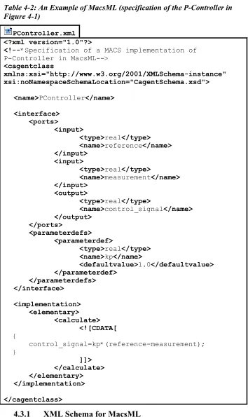
A MacsML specification of the P-Controller (schematically illustrated in Figure 4-1) is illustrated in Table 4-2. Similar to MACL, MacsML also uses a plain text format. In the example, boldface typesetting is used to highlight XML tags. The specification specifies the name, input ports, output port, parameter and ‘calculate():void’ method of the Elementary Agent. A Schema CagentSchema.xsd is assigned to the specification (PController.xml, Line: 6,
Table 4-2: An Example of MacsML (specification of the P-Controller in Figure 4-1)
PController.xml <?xml version="1.0"?>
<!--*Specification of a MACS implementation of P-Controller
<cagentclass
xmlns:xsi="http://www.w3.org/2001/XMLSchema-instance" xsi:noNamespaceSchemaLocation="CagentSchema.xsd">
in MacsML-->
<name>PController</name>
<interface> <ports>
<input>
<type>real</type> <name>reference</name>
</input>
<input>
<type>real</type>
<name>measurement</name>
</input>
<output>
<type>real</type>
<name>control_signal</name>
</output>
</ports>
<parameterdefs>
<parameterdef>
<type>real</type> <name>kp</name>
<defaultvalue>1.0</defaultvalue>
</parameterdef>
</parameterdefs> </interface>
<implementation> <elementary>
<calculate>
<![CDATA[
{
control_signal=kp*(reference-measurement); }
]]>
</calculate>
</elementary> </implementation>
</cagentclass>
4.3.1
XML Schema for MacsML
of the specification of Sensor, Actuator, Elementary and Composite Agents. CoordinationSchema.xsd describes the structure of the specification of Coordination Objects and MacSchema.xsd defines the structure of the specification of Main Agents. Important descriptions of the structure of the MacsML are presented in following sections.
4.3.2
Basic Structure of MacsML
Every XML document should have a root element and all the other tags should be nested within the root element. A common root tag <cagentclass> is being used for Sensor Agents, Actuator Agents, Elementary Agents, Composite Agents and Coordination Object (CagentSchema and CoordinationSchema). For Main Agents (MacSchema), another root tag <mac> is introduced. The root tag of a specification differentiates Main Agent from other components, as Main Agent is a special agent of Multi-Agent Controller Systems, which interacts with the environment (the plant).
As illustrated in Table 4-3, Table 4-4 and Table 4-5, both the <cagentclass>
and <mac> elements have a sequence of nested elements of <name>,
<interface> and <implementation>. The <name> is an elementary node, which should contain the name of the agent. The <interface> node contains information of interface of the agent to other agents or in the case of Main Agent, the environment (the plant). The <interface> node is optional for CoordinationSchema, as Coordination Object may not require declaration of an interface, as the ports of a Coordination Object are defined implicitly to facilitate dynamic size of ports (see section comment).
The implementation of agents is described within the <implementation> node. The <implementation> node of Sensor, Actuators, Elementary and Composite Agents have a <sensor>, <actuator>, <elementary> and <composite> sub node respectively. The <implementation> node of Coordination Object has a
<coordination> sub node and Main Agent has a <composite> sub node. The implementation of agents is nested within the respective sub nodes.
Table 4-3: Basic Structure of specification of Sensor, Actuator, Elementary and Composite Agents (CagentSchema)
<cagentclass
xmlns:xsi="http://www.w3.org/2001/XMLSchema-instance" xsi:noNamespaceSchemaLocation="CagentSchema.xsd"> <name>...</name>
<interface> .
.
</interface> <implementation> .
.
Table 4-4: Basic Structure of specification of Coordination Agent (CoordinationSchema)
<cagentclass
xmlns:xsi="http://www.w3.org/2001/XMLSchema-instance" xsi:noNamespaceSchemaLocation="CoordinationObject.xsd"> <name>...</name>
<interface> .
.
</interface> <implementation> .
.
</implementation> </cagentclass>
Table 4-5: Basic Structure of specification of Main Agent (MacSchema)
<mac
xmlns:xsi="http://www.w3.org/2001/XMLSchema-instance" xsi:noNamespaceSchemaLocation="MacSchema.xsd">
<name>...</name> <interface>
. .
</interface> <implementation> .
.
</implementation> </mac>
4.3.3
Input Ports and Output Ports
Input Ports and Output Ports of an agent are described by <input> and
<output> tags. Type and name of an Input Port or Output Port is defined in the nested tags, <type> and <name>. For Sensor, Actuator, Elementary, Composite and Coordination Agents, the <name> node contains the name of the variable of the port and the <type> node contains the type of the variable. Variables defined in <input> node and <output> node can be referred to in the implementation of the specification. The only variable type currently implemented for the ports of Multi-Agent Controller Systems is ‘real’ (or equivalent C++ variable declaration, ‘double’). An example of an input port and output port declaration for an agent is shown in Table 4-6.
Table 4-6: Input Port and Output Port declaration of an agent
<input>
<type>real</type> <name>position</name> </input>
<output>
<type>real</type> <name>current</name> </output>
field contains the instance name of the Agent. An example of an input port and an output port declaration for a Main Agent is shown in Table 4-7.
Table 4-7: Input Port and Output Port declaration of an agent
<input>
<type>TwenteSensor</type> <name>positionSensor</name> </input>
<output>
<type>TwenteActuator</type> <name>currentSensor</name> </output>
4.3.4
Parameters Definitions and States
Parameter definitions and states are described by <parameterdef> and <state>
tags respectively. Similar to input and output ports, they also have <type> and
<name> sub nodes. In addition, a parameter definition has a <defaultvalue>
tag, which is the initial value of the parameter when the agent is instantiated. Parameters and States can have a variable type of ‘real’, ‘boolean’ or ‘Int’ (or equivalent C++ variable declaration, ‘double’, ‘bool’ or ‘int’). An example of a parameter definition and state declaration is shown in Table 4-8 and Table 4-9 respectively.
Table 4-8: Parameter Definition declaration of an agent
<parameterdef> <type>real</type> <name>kd</name>
<defaultvalue>1.0</defaultvalue> </parameterdef>
Table 4-9: State declaration an agent
<state>
<type>int</type> <name>cycle</name> </state>
4.3.5 Method
Specification
Table 4-10: Declaration of activation method an agent
<activation> <![CDATA[
{
if (load_position>Max_Load_Pos_Limit)
return 1.0;
else
return 0.0;
}
]]>
</activation>
4.3.6
Controller Agents within Composite or Main Agent
Controller Agents in a Composite or Main Agent are specified by <cagent> tag. The <type> tag of the specification consists of the type of the Controller Agent and the <name> tag consists of the instance name of the Controller Agent. In addition, the <parameters> tags consist of initialization of parameters, which include the name of the parameter and its initial value. An example of a declaration of a controller agent is illustrated in Table 4-11.
Table 4-11: Declaration of a Controller Agent within a Composite Agent
<cagent>
<type>PosLimit</type> <name>posLimit</name> <parameters>
<parameter>
<name>kp</name> <value>25</value> </parameter>
<parameter>
<name>kd</name> <value>22</value> </parameter>
</parameters> </cagent>
4.3.7
Coordination within Composite or Main Agent
Similar to the declaration of Controller Agents, a Coordination Agent declaration also has a <type> and <name> tag. However, only one Coordination Object is allowed within a Composite or Main Agent. An example of declaration of a Coordination Object is presented in Table 4-12.
Table 4-12: Declaration of Coordination Object in some agent
<coordinationclass>
4.3.8
Connections within Composite or Main Agents
Connections within Composite or Main Agent are specified in <from> and
<to> tags. The <from> tag contains the source of the connection, an External Input or an Output, whereas the <to> tag contains the destination of the connection, an Input Port or an External Output Port. As mentioned in Section 3.3.1, an EIEO connection is non functional thus connections from an External Input to an External Output are not permitted. External Input Ports and External Output Ports are specified by their name. Input ports and output ports of controller agents within a composite or main agent are specified by name of the controller agent followed by a dot and the name of the port. An example of a connection between an external input port, ‘reference’, and an input port, ‘reference’, of a controller agent, ‘simpleController’, is illustrated in Table 4-13.
Table 4-13: Declaration of connection
<connection>
<from>reference</from>
<to>simpleController.reference</to> </connection>
Name of External Input Port
Name of Input Port Name of Controller Agent
4.3.9
Including Header Files
Header files, which are required for the specification of an agent, can be enclosed within <include> tags. The specification can have multiple includes. An example of the <include> tag is presented in Table 4-14. In the example, a header file “cmath” is included in the specification, which is required for use of the “fabs” function.
Table 4-14: Declaration of inclusion of a header file
<include>cmath</include> .
.
<activation><![CDATA[ {
)(fabs(error)<maxError));
return ((double
}]]></activation>
4.3.10 Instances of C++ Classes
Table 4-15: Declaration of instance of C++ class
<instances>
<instance>
<type>EncoderInterface</type> <name>encInt</name>
</instance> </instances>
4.4 Conclusion
The specification language, MACSL, developed by van Breemen [23] has been briefly introduced and development of the XML based specification language, MacsML, has been presented. MacsML improves the structure of the specification of Multi-Agent Controller Systems and provides a basis for future extensions. The Schemas designed define the structure of MacsML. These Schemas can be easily extended to support additional functionalities of Multi-Agent Controller Systems.
C
HAPTER
5
5
D
ESIGN AND
I
MPLEMENTATION OF
M
ULTI
-A
GENT
C
ONTROLLER
S
YSTEMS
5.1 Introduction
Multi-Agent Controller Systems are implemented in ANSI C++. The operating principle of Multi-Agent Controller Systems is presented in this section. Based on the operating principle, a C++ library is developed for Multi-Agent Controller Systems. The code generated for a Multi-Agent Controller System is combined with the library and simulated with Sim and implemented with 20-Works in real systems. The interface of 20-Sim and 20-20-Works with Multi-Agent Controller Systems is presented in this section. In addition, keywords used in the specification of agents are briefly discussed.
5.2
Operating Principle of Multi Agent Controller
Systems
5.2.1
Multi-Agent Controller Systems and the Environment
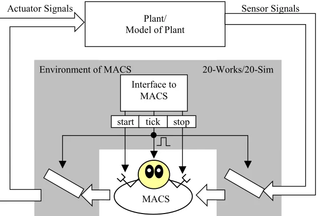
Multi-Agent Controller Systems have a common interface with their environments. A Multi-Agent Controller System has a Main Agent, which is responsible for interacting with its environment. The Main Agent has Sensor Agents and Actuator Agents to transfer data from or to the environment.
Plant/ Model of Plant
MACS
20-Works/20-Sim Interface to
MACS Environment of MACS
Actuator Signals Sensor Signals
start tick stop
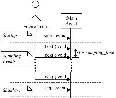
Figure 5-1: Schematic diagram of Multi-Agent Controller Systems The Main Agent has three main operations namely ‘start():void’, ‘tick():void’ and ‘stop():void’, as defined in the framework of Multi-Agent Controller Systems, which are invoked by the environment. The ‘start():void’ method is called during the startup of the Multi-Agent Controller System. This method initializes the Multi-Agent Controller System. The Controller System is implemented as a discrete system with a fixed sampling period. At each sampling instant, the sensor signals and actuator signals of the plant are sampled when the ‘tick():void’ method is invoked. The ‘stop():void’ method is called during the shutdown of the Multi-Agent Controller System and it runs the shutdown sequence of the System.
A sequence diagram of the Multi-Agent Controller System is presented in Figure 5-2. The environment (20-Sim or 20-Works) calls the ‘start():void’ method in the startup of the system. Each sampling event of the environment invokes the ‘tick():void’ method. Finally, at the shutdown of the system, the ‘stop():void’ method is called. A detailed description of the operating principle of 20-Sim and 20-Works is presented in section 5.4 and section 5.5 respectively.
5.2.2 Main
Agent
three events are presented in Figure 5-3 (a), (b) and (c). These sequence diagrams can be considered as cascaded with the main sequence diagram of the Multi-Agent Controller System presented in Figure 5-2. In a Main Agent, Controller Agents are coordinated by its Coordination Object as described in Section 5.2.5.
Startup
Shutdown Sampling Events
start( ):void :Main Agent
tick( ):void tick( ):void
tick( ):void stop( ):void
t = sampling_time
Environment
Figure 5-2: Sequence diagram of operation of MACS
In addition, Main Agent could have multiple Sensor Agents and Actuator Agents. Main Agent invokes methods of each of the Agents. The order of execution of methods is the same as the order of definition of the Agents in their specification. For example, in the specification of a Main Agent ‘MA1’, Sensor Agents ‘SA1’ and ‘SA2’ are defined consecutively (as illustrated in Table 5-1). The start method of MA1 will invoke the start method of SA1 first and then the start method of SA2.
Table 5-1: A part of Specification of a Main Agent ‘MA1’
Main Agent: MA1.xml
<name>MA1</name> <interface> <ports>
<input>
<type>SensorType1</type> <name>SA1</name>
</input>
<input>
<type>SensorType2</type> <name>SA2</name>
start( ):void :Main
Agent :SensorAgent
:Actuator Agent
:Coordination Object
start( ):void
start( ):void
start( ):void
(a) :Main
Agent :SensorAgent :Actuator Agent :Coordination Object tick( ):void
sense( ):void
actuate( ):void
resolute( ):void decide(bool ack) :void combine( ):void
(b)
stop( ):void :Main
Agent :SensorAgent
:Actuator Agent
:Coordination Object
stop( ):void
stop( ):void
stop( ):void
(c)
Figure 5-3: Sequence diagrams of Main Agent
5.2.3 Sensor
Agent
Sensor Agent is a basic agent, thus does not have sub agents. Thus, the event received by Sensor Agent does not trigger other events. Sensor Agent has three events namely, ‘start():void’, ‘sense():void’ and ‘stop():void’. These methods execute the code sequence stated in its specification. The ‘sense():void’ method contains code sequence to acquire sensor data from the environment. Other two methods run the startup and shutdown sequence of the agent.
5.2.4 Actuator
Agent
method provides actuator signals to the environment. The other two methods run the startup and shutdown sequence of the actuator.
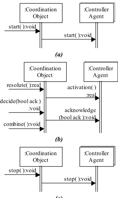
5.2.5 Coordination
Object
Coordination Object is contained within a Composite Agents or Main Agent. Composite or Main Agent have a set of Controller Agents and Coordination Object is associated with the Controller Agents. Events of Coordination Object trigger events of the Controller Agents. Sequence diagrams of Coordination Object are shown in Figure 5-4. Controller Agent could be a Composite Agent or an Elementary Agent.
:Controller Agent :Coordination
Object start( ):void
start( ):void
(a)
:Controller Agent :Coordination
Object
resolute( ):real activation( ) :real decide(bool ack )
:void acknowledge (bool ack ):void combine( ):void
(b)
:Controller Agent :Coordination
Object stop( ):void
stop( ):void
(c)
Figure 5-4: Sequence diagrams of Coordination Object
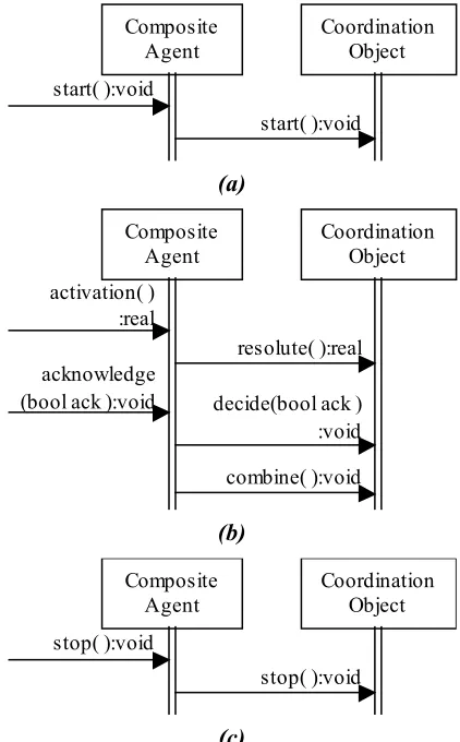
5.2.6 Composite Agent
Coordination Object
start( ):void Composite
Agent start( ):void
(a)
Coordination Object
resolute( ):real
decide(bool ack ) :void combine( ):void Composite
Agent activation( )
:real
acknowledge (bool ack ):void
(b)
Coordination Object
stop( ):void Composite
Agent stop( ):void
(c)
Figure 5-5: Sequence diagrams of Composite Agent
5.2.7 Elementary Agent <