Performance Comparison of OFDM System
with Different Modulation Schemes Using
ISP Pulse Shaping Technique
Omkar Pabbati, Divyangna Gandhi
Assistant Professor, Department of E&C, Indus University, Ahmedabad, India
ABSTRACT: Amazing advancement has been built up in wireless communication system because of achievement of OFDM system. In spite it's many favorable advantages, performance of OFDM system is ruined because of the CFO (Carrier recurrence offset).Doppler shift and frequency mismatch are responsibility of presenting CFO which is overwhelm the orthogonally between the subcarriers and generate ICI. In this paper
evolution of CFO-OFDM system using ISP is assessed with different modulation schemes (BPSK, QPSK,
8-PSK, 16-PSK) in term of BER. A result acquired by simulation demonstrates that CFO-OFDM using ISP with BPSK gives better performance compared to other modulation scheme. MATLAB software has been used for simulation result.
KEYWORDS: Carrier Frequency Offset Orthogonal Frequency Division Multiplexing (CFO-OFDM), Improved Sinc Power pulse (ISP), Inter Carrier Interferences (ICI), Signal to Noise Ratio (SNR), Bit Error Rate (BER),Binary shift keying(BPSK), Quadrature shift keying(QPSK), Phase shift keying(PSK).
I. INTRODUCTION
It has been proven that Orthogonal Frequency Division Multiplexing (OFDM) system has reached high data speed transmission in wireless environment due to its ability to decompose a wideband frequency selective fading channel in to several parallel narrow band flat fading channels [1],[2].Multi-path delay spread tolerance, immunity to frequency selective fading channels, high spectral efficiency, efficient modulation and demodulation techniques and robust to impulse noise are the foremost advantages of OFDM system [3],[4]. OFDM technique has potential of increasing the data rate in band limited channel. However, inter-carrier interferences (ICI) and high peak to average power ratio (PAPR) are main downsides of OFDM system [2],[3].
A considerable research has been accomplished for diminishing the two significant restrictions of OFDM system and to boost up the overall performance of the system. One of the impairment is sensitivity of OFDM system against carrier frequency offset which obliterates the orthogonality amongst subcarriers and causes inter-carrier interferences (ICI) [2],[3],[4],[5],[6],[7],[8]. Several methods have been offered to reduce ICI, Frequency domain equalization,
windowing at the receiver, ICI self-cancellation and use of pulse shaping [9]. Another one is the large variation in
envelope of OFDM signal, which causes high peak-to-average power ratio (PAPR) [2],[3].
Simulation results show that introducing CFO degrades the performance and introducing ISP pulse shaping technique improved the performance with using different modulation scheme Also it has been observed that ISP pulse shape with BPSK modulation provides better performance in comparison of other modulation schemes.
II. SYSTEMMODEL
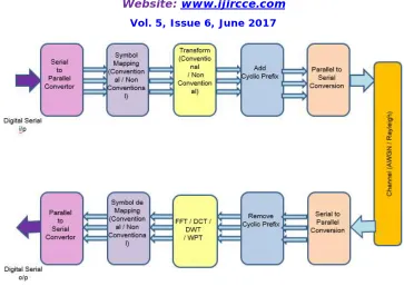
OFDM communication system with pulse shaping function has been shown in Figure 1. In this system QPSK constellation is used to map binary information. The high speed serial data stream is split up in to a set of low speed sub streams and modulated onto the orthogonal carriers through Inverse Fast Fourier transform (IFFT). Signal s (t) which is represented as in (2.1) is transmitted through the channel with ISP pulse shaping functions [2].
OFDM block with pulse-shaping is represented as:
t k f j N k k t c f j
e
t
p
D
e
t
s
1 20 2
)
(
)
(
(2.1)Where j=
1
, Number of subcarrier is N, Carrier frequency of OFDM system isf
c, Subcarrier frequency of theth
K
subcarrier isf
k, Where k = 0, 1… N – 1, Time limited pulse shaping function is p (t). Transmitted symbol isD
kwhich is assumed to have zero mean and normalized average symbol energy. Also we consider that all data symbols are uncorrelated [10, 11] i.e.:
1
,....,
1
,
0
,
,
,
0
1
,....,
1
,
0
,
,
,
1
*N
m
k
m
k
N
m
k
m
k
D
D
E
k m(2.2)
Where
D
*m is the complex conjugate ofD
k.To ensure the orthogonality of subcarrier, it is very important to satisfiedthe below equation for OFDM system [10, 11]. The subcarrier frequency is
;
s k
T k
f k0,1,...N1
, s m k T m k f
f k,m0,1,...,N1 (2.3)
For maintaining orthogonality between subcarriers, the minimum required subcarrier frequency spacing is 1/
T
s.Thereceived signal at the receiver can be represented as:
) ( ) ( ) ( )
(t s t h t w t
r
(2.4)
In above equation convolution is denoted by
, h (t) is the channel impulse response and the additive white Gaussiannoise is represented by w (t) which process with zero mean and variance
N
0/
2
per dimension.For this work we assume that the channel is ideal, i.e., h (t) =
(
t
)
in order to investigate the effect of the frequencyoffset only on the ICI performance. At the receiver, the received signal r’ (t) becomes:
t
e
j fctr
(
)
2
j f t j f f tN
k
k
c
k
w
t
e
e
t
p
D
2 21 0
)
(
)
(
(2.5)
Figure 1 Simulation block diagram of OFDM System
III. PULSE SHAPING FUNCTION WITH DIFFERENT MODULATION SCHEMES
In the OFDM spectrum each carrier is represented by main lobe with a number of side lobes having lower amplitudes. Since peak power is associated with main lobe and ICI power is associated with side lobes, so the intention of pulse shaping function is to increase the width of main lobe and/or reduce the amplitude of sidelobes [10]. Proper pulse shaping techniques makes a digital communication system possible to transmit data within a limited BW with minimum ISI [12, 13].
The performance of OFDM system depends on several factors, such as the modulation schemes used, the amount of multipath, and the level of noise in the signal. Different modulation schemes are used like BPSK.QPSK, 8-PSK and 16-PSK
Digital modulation provides more information capacity, compatibility with digital data services, higher data security, better quality communications, and quicker system availability. The type of modulation used depends on the type of the communication channel. The type of modulation used depends on the type of the communication channel. Bit rate and symbol rate term gives us understanding and comparison of different modulation format efficiencies, the signal bandwidth for the communications channel needed depends on the symbol rate, not on the bit rate.
BPSK: One of the simplest forms of digital modulation is binary or Bi-Phase Shift Keying (BPSK). The phase of a constant amplitude carrier signal moves between zero and 180 degrees. So they are chosen is that they have a correlation coefficient of -1, which leads to the minimum error probability [14].
Figure 2: BPSK constellation
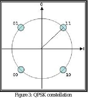
QPSK: Quadrature means that the signal shifts between phase states which are separated by 90 degrees. This gives
maximum phase-separation between adjacent points and thus the best immunity to corruption. The signal shifts in
increments of 90 degrees from 45 to 135, –45, or –135 degrees.
` All constellation points have same energy on circle. Only two Ivalues and two Q values are needed and this
gives two bits per symbol. There are four states because 22 = 4. It is therefore a more bandwidth-efficient type of
Modulation than BPSK, For QPSK theoretical bandwidth efficiency is 2 bit/second/Hz potentially twice as efficient.
Figure 3: QPSK constellation
In this section ISP pulse shaping functions have been introduced with different modulation schemes and its Fourier transforms are given, as [2, 3, 4, 7, 10, and 13].
The pulse shaping functions is
)
(
sin
)
)
(
exp(
)
(
f
a
fT
2c
fT
P
ISP
n (3.1)
IV. SIMULATION RESULTS
To demonstrate the performance enhancement of shaping the CFO-OFDM system, the simulation results have been done by using different modulation scheme with ISP time-limited pulse shaping function which have been mentioned in section 3.
4.1 Impulse response of ISP pulse with values of a (0.5, 1).
Figure 4 Impulse response of ISP pulse shape.
ISP pulse is depicted in Figure 4 with values of ‘a’ (0.5, 1) where the amplitude of ISP pulse is adjusted by varying a
design parameter ‘a’and n is the degree of the sinc function. As the value of design parameter ‘a’ increases from 0.5 to
1, the width of the main lobe is further reducing up to some extent. But after that for very large values of a, ISP pulse
shape become to a very narrow pulse shape which is not preferred for the system having frequency offset.
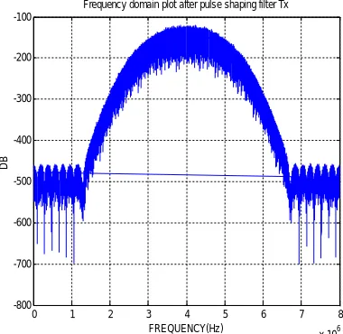
4.2 Frequency Spectrum of ISP pulse
Figure 5 Spectrum performance using ISP
0 1 2 3 4 5 6 7 8
x 106 -800
-700 -600 -500 -400 -300 -200 -100
FREQUENCY(Hz)
D
B
Frequency Spectrum of ISP pulse has been shown in figure 5.From the simulation result it can be observed that ISP is showing better spectrum because width of main lobe is increases and the amplitude of side lobes is reduces .So ultimately its reduces ICI and ISP is more spectrum efficient in comparison of without pulse shaping technique.
4.3 BER of OFDM system
Simulation parameters which have been used are as follows:
FFT size: 64; No. of subcarriers: 52; No. of Symbols: 10000 and 2 bits per symbol. Channel: AWGN. Cyclic prefix duration: 0.8µs. SNR: 1 to 25.Modulation scheme: BPSK
4.3.1 BER comparison of OFDM system without CFO and without ISP
Figure 6: BER Comparison of OFDM without CFO and ISP
The OFDM without CFO and without ISP has been shown in Figure 6, where the BER is shown as a function of SNR.
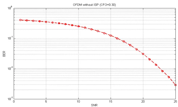
4.3.2 BER comparison of OFDM with CFO without ISP
It is observed that from figure 7 BER without ISP pulse shaping technique the BER performance is degrade with CFO-OFDM system.
4.3.3 BER comparison of OFDM with different modulation schemes without CFO using ISP
Fig 8 BER improvement of OFDM system without CFO using ISP technique
It has been observed from figure 8 BER of BPSK modulation is less compared to other modulation schemes without CFO.
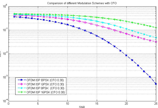
4.3.4 BER comparison of OFDM with different modulation schemes and CFO using ISP
OFDM system with different modulation schemes and CFO using ISP pulse shaping function as depicted in figure 9.It has been observed that the BER performance degrades by approximately 3 dB with BPSK and CFO by using ISP pulse shaping.
V. CONCLUSION
In this paper, the performance of CFO-OFDM system with different modulation scheme using ISP pulse shaping technique has been evaluated in terms of SNR and BER. From the simulation results it has been observed that Introducing CFO degrades the performance and shaping the OFDM system by ISP pulse with BPSK provide better performance compared to other modulation schemes.
REFERENCES
[1] S. D. Assimonis, M. Matthaiou, G. K. Karagiannidis and J. A. Nossek, “OptimizedBetter ThanRaised-Cosine Pulse for Reduced ICI in OFDM Systems”, in 17th International Conference on Telecommunications, 2010.
[2] M.Palaivelan, S. Anand and S. P. Venkatesan. 2012. “PAPR and ICI Reduction in OFDM Systems using Modified Raised Cosine Power Pulse Shape”, European Journal of Scientific Research ISSN 1450-216X Vol.72 No.4 (2012), pp. 618-627.
[3] Srabani Mohapatra and Susmita Das. 2009. “A New Approach For Performance Improvement of OFDM System Using Pulse Shaping”, M.Tech Thesis.NIT Rourkela.
[4] S. Aenagandula, A. Kumar, Srinivas K. and M. Nanda, “ Inter Carrier Interference and Signal to Interference Ratio of various Pulse Shaping Functions used in OFDM System with Carrier Frequency Offset”, International Journal of Electronics Signals and Systems (IJESS) ISSN: 2231-5969, Vol-1 Iss-3, 2012.
[5] J. Armstrong. “Analysis of new and existing methods of reducing intercarrier interference due to carrier frequency offset in OFDM”, IEEE Transactions on Communications, vol. 47, no. 3, pp. 365–369, Mar- 1999.
[6] H.M. Mourad. 2006. “Reducing ICI in OFDM systems using a proposed pulse shape”, Wireless Person. Communications. (2006) 40: 41–48. [7] Volkan Kumbasar and O˘guz Kucur. 2007. “ICI reduction in OFDM Systems by using improved sinc power pulse”, Digital Signal Processing
17 (2007) 997–1006.
[8] Srabani Mohapatra and Susmita Das, “Performance Enhancement of OFDM System with ICI Reduction Technique”, In Proceedings of the World Congress on Engineering, Vol. I, July, 2009.
[9] R.sukanesh and R.Sundaraguru.”ICI Reduction in OFDM Systems by using Phase Factor Optimization Technique”, In European Journal of Scientific Research, ISSN: 1450-216X Vol.52 No.3 (2011).
[10] Nadieh M. Moghaddam and Mohammad Mohebbi, “ICI Reduction Methods in OFDM Systems," Recent Advance in wireless Communication and Networks, Prof. Jia-Chin Lin (Ed.), ISBN: 978-953-307-274-6, In Tech.
[11] P. Tan, N.C. Beaulieu. 2004. “Reduced ICI in OFDM systems using the better than raised-cosine pulse”, IEEE Commun. Lett. 8 (3) (2004) 135– 137.
[12] Mahua Pal, “Algorithm for sharpening Raised Cosine Pulse shaping Digital Filter and Analysis of Performance Of QAM system when subjected to Sharpened Raised Cosine Filter”, International Journal Of Scientific and Research Publication, Volume 2, Issue 1, January 2012. ISSN 2250-3153.
[13] Divyangna Gandhi and Shilpi Gupta “Implementation of Pulse Shaping Techniques in OFDM System” in International Journal of Computer Application (0975-8887) Volume 68-N0.10, April-2013.
[14] Fuqin Xiong, Digital modulation techniques. ch 4 and ch 10. books.google.ca/books/about/digital_modulation_techniques.ht.