ABSTRACT
FEBRANSYAH, ADE. A Feature-based Approach to Automating High-Level Process Planning. (Under the direction of Professors Ezat T. Sanii and Denis R. Cormier)
High-level process planning plays an important role in determining candidate process domains at the configuration design stage. Changing the processes domains later increases the product development cycle and the product development cost. Therefore, determining the most appropriate manufacturing processes at the beginning stages of the design process becomes critical. However, high-level process planning systems have traditionally lacked integration of design synthesis and design evaluation.
The main objective of this research has been to develop a FEature-Based Design And Process Planning (FEBDAPP) system that helps designers decide whether or not the design is worth pursuing by providing manufacturing advice to designers during the design process. In order to achieve the main objective, the following tasks have been accomplished: (1) developed a hybrid system incorporating design by feature and feature recognition approaches capable of reducing the complexity of feature recognition algorithms without sacrificing flexibility in creating a part design, (2) developed a comprehensive set of feature mapping algorithms capable of transforming a primary part representation into a secondary part representation that is required as input to downstream applications, and (3) developed a CAD-based interface capable of integrating a current CAD system with a high-level process planning system.
BIOGRAPHY
Ade Febransyah was born on February 2, 1965 in Jakarta, Indonesia. He attended Bandung Institute of Technology and received a Bachelor of Science degree in Mechanical Engineering in 1988. Following his graduation, he spent three years in industrial sector mostly working as a mechanical engineer. In 1992, he pursued a Master’s degree in mechanical engineering at Oklahoma State University. After receiving his degree in 1994, he went back to Indonesia and worked as a research associate in the energy industry. In 1997, he started his Ph.D. study in the Department of Industrial Engineering at North Carolina State University.
ACKNOWLEDGEMENTS
I would like to thank the Co-Chairs of my Advisory Committee, Dr. Ezat T. Sanii and Dr. Denis R. Cormier for their advice, assistance, patience, and encouragement during the course of this research. I am deeply thankful for being introduced to the fascinating area of research pursued for my dissertation. I would also like to thank Dr. Michael G. Kay and Dr. Fen Wu for their roles on my advisory committee. Also, I would like to thank Dr. Kristin A. Thoney who represented the Graduate School in my Ph.D. oral examination.
Special thanks are due to Dr. Ronald E. Giachetti for providing me the Material and Manufacturing Process Selection (MaMPS) software. Without it, this dissertation would have taken a different and less efficient approach.
I dedicate this dissertation to my parents who always reminded me the importance of education. Their endless encouragement is very much appreciated.
TABLE OF CONTENTS
Page
LIST OF TABLES………..VII
LIST OF FIGURES………viii
1. INTRODUCTION... 1
1.1 Background ... 1
1.2 Process Planning ... 2
1.1.1 Conceptual Design ... 4
1.1.2 Detailed Design ... 4
1.3 Current Process Planning Systems... 5
1.4 The Role of Feature Technology in Process Planning... 6
1.5 Problem Definition... 7
1.6 Organization of the Dissertation ... 8
2. LITERATURE REVIEW... 9
2.1 High-Level Process Planning... 9
2.1.1 Computer Aided Process/Material Selection ... 9
2.1.2 Expert Processing Sequence Selector ... 10
2.1.3 Computer-Aided Design for Manufacturing Process Selection... 11
2.1.4 Cambridge Materials and Process Selector (CMS and CPS)... 11
2.1.5 Computer Oriented Materials, Processes, and Apparatus Selection System (COMPASS)... 13
2.1.6 Material and Manufacturing Process Selection (MaMPS)... 14
2.1.7 Manufacturing Advisory Service (MAS)... 14
2.1.8 Process First and Material First Approaches... 15
2.1.9 Others ... 16
2.2 Feature Technology ... 20
2.2.1 Feature recognition... 23
2.2.2 Design by Feature... 25
2.2.3 Feature-Based Design and Process Planning ... 26
2.3 Summary of the Existing High-Level Process Planning Systems ... 27
3. RESEARCH OBJECTIVES... 29
4. FRAMEWORK OF THE FEBDAPP SYSTEM... 31
4.1 Concept of a Hybrid System ... 34
4.2 Part Creation ... 38
4.2.1 The Preparation Stage: Feature Library Creation ... 39
4.2.1.1 Base Features ... 40
4.2.1.2 Add-on Features... 40
4.2.1.3 User-Defined Features ... 42
4.2.2 The Modeling Stage: Part Creation using a Feature-based Volumetric Sketching ... 44
4.2.3 Part creation in sketch-based modeling... 46
4.3 Primary Representation... 47
4.4 Feature Mapping ... 48
4.4.1 Application-based features ... 50
4.4.2 Procedures for extraction of application-based features ... 51
4.5 System Integration ... 52
4.5.1 Object-oriented approach ... 55
4.5.2 Inside MaMPS... 57
5. APPLICATION-BASED FEATURES... 60
5.1 Basic shape definition ...61
5.2 Incremental shape definition ...72
5.3 Extraction of low-level feature information...75
5.3.1 Feature Object ...75
5.3.2 Feature relationship ...82
5.4 Wall thickness ...84
5.4.1 Surface tesselation...86
5.4.3 Wall thickness selection ...89
5.5 Undercut detection ...89
5.5.1 Fundamentals ...89
5.5.2 Planar versus Non-Planar Parting Surfaces...92
5.5.3 Determining the number of undercuts...93
5.6 Cost Analysis...101
5.6.1 Secondary Representation for Cost Analysis ...102
5.6.2 Tooling Cost...104
6. IMPLEMENTATION AND TESTING... 106
6.1 System Implementation ... 106
6.2 Part Shape ... 108
6.3 Wall thickness... 110
6.4 Parting surface and undercuts ... 112
6.4.1 Planar parting surface with no undercuts ... 116
6.4.2 Planar parting surface with undercuts ... 117
6.4.3 Non-planar parting surface with no undercuts ... 117
6.4.4 Non-planar parting surface with undercuts ... 119
6.5 Candidate Processes... 120
6.6 Relative Tooling Cost ... 123
6.7 High-level description of the FEBDAPP system... 126
7. SUMMARY AND CONCLUSION... 132
7.1 Summary ... 132
7.2 Research Contributions ... 134
7.3 Recommendations for Further Research... 135
REFERENCES... 137
APPENDIX A RELATIVE TOOLING COSTS ESTIMATES FOR INJECTION MOLDING AND DIE CASTING... 145
LIST OF TABLES
Page
Table 2.1 Geometry Information Comparison ... 17
Table 2.2 Summary of Existing Process Selection Systems ... 18
Table 2.3 Definition of Features [Kim 1994]... 22
Table 4.1 A Basic Set of Base Features ... 41
Table 4.2 Examples of positive and negative features ... 42
Table 5.1 Production rules for shape definition ...70
Table 5.2 Decision table for incremental shape definition up to 2nd feature...76
Table 5.3 Decision table for incremental shape definition after 2nd feature...77
LIST OF FIGURES
Page
Figure 1.1 Typical Steps in Concurrent Engineering [Boothroyd 1995]... 3
Figure 1.2 Current Practice in Design ... 7
Figure 2.1 CPS screening stage ... 12
Figure 2.2 Process-First Approach ... 16
Figure 2.3 Material-First Approach... 16
Figure 4.1 The Framework of the FEBDAPP System... 32
Figure 4.2 Proposed product development process ... 35
Figure 4.3 A simple rotational part... 36
Figure 4.4 An example of a user-defined feature ... 43
Figure 4.5 An Example of Feature Creation... 44
Figure 4.6 Feature orientation... 46
Figure 4.7 An example of the of reference plane ... 47
Figure 4.8 Part Structure [Latif 1993] ... 49
Figure 4.9 Procedures for extracting application-based features... 53
Figure 4.10 A scheme of CAD-Applications integration ... 54
Figure 4.11 Object-oriented approach for a part model ... 56
Figure 4.12 MaMPS’ architecture [Giachetti 1998] ... 58
Figure 4.13 MaMPS’ data structure representation ... 59
Figure 5.1 Solid axial part creation...63
Figure 5.2 A part is created from revolving and shelling ...64
Figure 5.3 A part is created from revolving only ...64
Figure 5.4 A hollow axial is created by extruding and cut-extruding ...64
Figure 5.5 An example of prismatic part ...65
Figure 5.6 Creation of primary shape of rounded box...66
Figure 5.7 Example of the primary shape of a cover...67
Figure 5.8 Example of a round flat primary shape ...68
Figure 5.9 Example of a square flat primary shape ...68
Figure 5.10 Primary shape of a cone axial part ...68
Figure 5.11 An example of the primary shape of a tank from sweeping...69
Figure 5.12 Incremental shape definition procedure ...73
Figure 5.13 Effect of negative features...73
Figure 5.14 Effect of negative features in part shape definition...74
Figure 5.15 Pseudocodes for defining feature objects...78
Figure 5.16 A part composed of cylindrical features ...82
Figure 5.17 Pseudocodes for determining feature relationship ...82
Figure 5.18 Potential wall thickness...83
Figure 5.19 Non-potential wall thickness ...83
Figure 5.20 Facet P1P2P3...85
Figure 5.21 A plane and its normal vector ...86
Figure 5.22 Undercuts are detected ...87
Figure 5.23 No undercuts are detected ...88
Figure 5.24 Planar parting plane...90
Figure 5.25 A part with no undercut and non-planar parting surface...91
Figure 5.26 Concept of visibility ...92
Figure 5.27 Parting plane type determination...93
Figure 5.28 A part with an undercut ...94
Figure 5.29 Part box envelope ...95
Figure 5.30 The top view of the temporary body ...95
Figure 5.31 The front view of the temporary body ...96
Figure 5.32 Planar parting plane with potential undercuts ...97
Figure 5.33 Non-planar parting plane in reducing numbers of undercuts ...98
Figure 5.34 Pseudocodes for determining the number of internal and external undercuts………..101
Figure 5.35 Pseudocodes for determining the type of parting surface………102
Figure 5.36 Pseudocodes for determining the type of mold………103
Figure 6.1 The FEBDAPP system’s architecture ... 107
Figure 6.3 Incremental shape definition ... 109
Figure 6.4 A solid axial part ... 110
Figure 6.5 Error from the inner surface ... 112
Figure 6.6 Error from the outer surface ... 113
Figure 6.7 The problem in determining the surface visibility ... 114
Figure 6.8 Shifted basepoints ... 115
Figure 6.9 A part with planar parting surface and no undercuts ... 116
Figure 6.10 FEBDAPP’s output for planar parting surfaces and no undercuts... 117
Figure 6.11 A part with planar parting surface without undercuts ... 118
Figure 6.12 Output for planar parting surface with undercuts... 118
Figure 6.13 A part with non-planar surface without undercuts ... 119
Figure 6.14 Output non-planar parting surface without undercuts... 119
Figure 6.15 A part with non-planar parting plane and with undercuts ... 120
Figure 6.16 Output for non-planar parting plane with undercuts ... 120
Figure 6.17 Candidate process for the solid axial part in Figure 6.4... 121
Figure 6.18 A screw... 122
Figure 6.19 Candidate processes for the screw ... 122
Figure 6.20 A reference part ... 123
Figure 6.21 Tooling cost estimate for the reference part... 124
Figure 6.22 Tooling cost for the solid axial part ... 125
Figure 6.23 A motor mounting plate ... 126
Figure 6.24 FEBDAPP’s main window... 127
Figure 6.25 FEBDAPP’s application-based feature window ... 128
Figure 6.26 MaMPS’ process selection form ... 129
Figure 6.27 MaMPS’ process selection table ... 130
Figure 6.28 MaMPS’ filter process selection query ... 130
Figure 6.29 FEBDAPP’s tooling cost window... 131
1. I
NTRODUCTION1.1 Background
It is widely believed that a large percentage of product costs are determined during engineering design. One analysis shows that at least 70% of the product’s final costs are set by the decisions made during the design stage [Ullman 1992]. This implies that once a final design is completed, there is little opportunity to reduce the product cost since a significant portion of its cost is already determined. Based on this fact, companies strive to consider economic factors as early as possible in the design process.
In practice, the so-called over the wall approach is still commonly used, where designers work on product design and then throw the design over the wall to the manufacturing engineers [Boothroyd 1994]. The design engineers are only responsible for designs of products that can function properly without considering the manufacturability of their designs. A back and forth process usually occurs when the manufacturing engineers find that the designed products cannot be manufactured or are difficult to manufacture and thus they have to send the designs back to the design engineers for revision. This is a lengthy and expensive process that unnecessarily extends the product development cycle.
Lack of manufacturing knowledge among designers is considered the main cause of the current inefficient product development process. An experienced designer repeatedly chooses the manufacturing processes he or she is familiar with, without considering alternative processes and materials. For example, a designer with experience in die-casting tends to choose die-casting again and again for most design problems. In the current manufacturing industry where product designs change very rapidly and products are often made in small batches, this habit-driven mentality could be harmful to the process of innovation [Smith 1999].
2
the DFM analysis typically focuses on a specific manufacturing process domain, i.e. machining, die-casting, injection molding, stamping, etc. It is assumed that certain candidate processes have already been designated for a given part design before the DFM analysis can be made. The other fact is that DFM guidelines are employed when the part is in the detailed design stage. One important task preceding design for manufacture analysis is the selection of manufacturing processes at the preliminary stages of design.
Figure 1.1 shows the typical steps taken in a concurrent engineering environment using Design for Manufacture and Assembly (DFMA) techniques [Boothroyd 1994]. As designers complete the DFA analysis, the sketch of each part is already made. Before the designers go further into detailed design, they need to make decisions as to what processes and materials should be used to produce the part. This is not an easy task since there are numerous combinations of processes and materials that need to be considered.
Fortunately, there are material and process relationships that can eliminate some materials or processes from consideration. Dixon and Poli [Dixon 1995] propose either the material first approach or the process first approach to select process candidates. Both approaches should end up with the same result. In practice, a certain process is typically selected because of cost constraints, so an early cost estimate should be made in order to select the most economical process.
1.2 Process Planning
range of systems, from computer-aided process planning to fully automated process planning systems, has been developed.
Figure 1.1 Typical Steps in Concurrent Engineering [Boothroyd 1995]
On the other hand, the main goal of high-level process planning is principally to select the manufacturing processes and materials that can be used to form the part at the early stage of design. The early stage of design is associated with the stage where
Design concept
Design for Assembly (DFA)
Selection of materials and processes and early cost estimates
Best design concept
Design for Manufacture
(DFM)
Prototype
Production
Suggestion for simplification of product structure
Suggestion for more economic
materials and processes
Detailed design for minimum manufacturing
4
products have been conceptually designed. At this point, it is helpful to define what is meant by conceptual and detailed design.
1.1.1 Conceptual Design
Practically speaking, a conceptual design focuses on product structure rather than individual parts. At the conceptual stage, a product designer usually transforms his or her ideas by sketching a product configuration consisting of each individual part. At this stage, the emphasis is on the functionality of the configuration that will likely satisfy the product’s functional requirements. After a product has been conceptually defined, then designers create preliminary designs for its constituent components. At this stage, depending on the level of expertise of the designer, a specific combination of processes and materials is already on the designer’s mind. In some instances, process selection is not too challenging during conceptual design. The more challenging task is in determining how to obtain a reliable cost estimate for each part at the early design stage. The cost estimate affects the decision making process that determines whether a part will be made or purchased, or whether a detailed design is worth developing. As previously stated, the process and material selection is an easy task if the designer ignores any analysis and just selects the same process repeatedly. However, if one would like to consider all possible processes and materials, this task becomes much more difficult to properly accomplish.
1.1.2 Detailed Design
any detailed design activity. It is too late if a designer has not selected a process domain for each part prior to working on a detailed design. In good design practice, the designers should avoid making changes to the process domain after completing the detailed design. For example, suppose that injection molding is selected as the process domain during the preliminary part design, but that when the designer tries to elaborate on detailed specifications, it is found that injection molding is not suitable. The designer must then choose another process domain, such as die-casting, and the whole process is repeated. This practice can be harmful and may create a highly inefficient product development cycle [Smith 1999].
After a designer determines the process candidates for a preliminary part design, DFM techniques for the specific process domains are applied. If these DFM results suggest that the preliminary part design is difficult to manufacture due to certain features, then the design is revised in accordance with DFM techniques.
There are relatively few research activities related to high-level process planning. The lack of work in this area is perhaps due to the fact that the decision making activity of process and material selection is trivialized by adopting the past decisions or hastily selecting a seemingly obvious candidate proposed by an experienced designer. However, it should be noted that an experienced designer tends to repeatedly select the same processes and materials that he or she is familiar with. In fact, there are many process and material combinations that should be considered for producing a part, but most are often ignored.
1.3 Current Process Planning Systems
6
Figure 1.2 depicts the current practice in design. Designers start the design process by creating a conceptual design. Traditionally, this stage is done manually by hand drawing 2-D sketches or carved foam models. As mentioned earlier, a conceptual design is created to the approximate shape, size, and location. Once this conceptual design stage is done, a process planner (high-level) starts to consider candidate processes that can be used to produce the part. Currently, there is no CAD-based high-level process planning system and high-level process plans are still developed manually or with some kind of computer-assisted systems. After candidate processes are determined, DFM may be applied to develop the more detailed design, which includes exact dimensions, relations, and positions. This part information is then represented in a CAD model.
1.4 The Role of Feature Technology in Process Planning
In recent years, feature technologies such as design by feature and feature recognition have been used in an effort to realize the integration of CAD and CAM. Chapter 2 discusses these two approaches in feature-based systems. Design by feature or feature-based design has been mostly used in low-level process planning systems [Shah 1995, Mäntylä 1989, Cutkosky 1990]. However, these low-level process-planning systems mainly consider machining processes, and the features included are called machining or process planning features. If the design features represent the geometry construction units, then the machining or process planning features would represent the volume of material that needs to be machined. One of the shortcomings of designing with machining features is that only negative features, such as holes and slots, are considered [Shah 1995, Smith 1997]. The other shortcoming of this approach is that it only allows designers to create standardized or frequently used parts due to the limited of number of predefined features that can be stored. On the other hand, in the feature recognition based systems, designers work on an existing CAD system and feature recognition methods are implemented in the CAD system to recognize and extract the feature information from the CAD model.
this approach is that it requires complex algorithms, even for a simple feature, and the searching process can be very time consuming. Chapter 2 presents a review of existing design by features and feature recognition approaches.
Figure 1.2 Current Practice in Design
1.5 Problem Definition
This research focuses on the following specific problems: (1) The inefficiency of current practice in design
As previously discussed, the product development cycle using traditional practice in design can be time consuming since there is often a lack of communication between design and manufacturing engineers. There may be numerous design Conceptual design
process
Hand drawn 2-D sketches
Carved foam model
Approximate size, shape, and location
Detailed design process
Dimensions (length, diameter, angle etc.)
Relations (equal, concentric, tangent etc.)
Equations (i.e. length= C*width)
Position CAD
M d
Manual/Computer-based High-level Process Planner
Computer-based Low-level Process
Planner DFM
Design for Manufacturability
8
revisions where manufacturing engineers find that the design is too difficult or expensive to manufacture. Product development can be shortened if concurrent engineering efforts, where design and manufacturing engineers work simultaneously, are followed from the beginning. Alternatively, design engineers may be provided with a tool that can provide downstream information for their design. Therefore, an intelligent CAD-based solution interface system is recommended for design improvement purposes.
(2) Recognizing application-dependent features for non-machining process domains. Machining has consistently been used as the process domain in feature technology research. Several techniques for recognizing both negative and positive features of machined parts have been developed. Even though in non-machining process domains such as net-shape manufacturing processes, features to be recognized are quite different than those in machining processes, feature mapping still needs to be done in order to create a more intelligent CAD system.
1.6 Organization of the Dissertation
2. L
ITERATURER
EVIEW2.1 High-Level Process Planning
A great deal of research has been performed in the area of process planning. Most of this research is concentrated on the development of manufacturing processes with detailed specifications such as jigs and fixtures, machine tools, tooling, machining parameters, etc. The Computer-Aided Process Planning (CAPP) systems rely on detailed part specifications. The proposed research aims to provide an early determination of process and cost estimates while the part is being designed. This is referred to as high-level process planning (HLPP). The output of HLPP may influence the detailed design specifications. No effort is made here to provide a review of “low-level” process planning research. Research on low-level process planning is well documented by Alting and Zhang [Alting 1989].
There is a large body of research related to low-level process planning including the development of various CAPP systems for machined parts. However, there has been relatively little work done in the area of high-level process planning. In this chapter, some important research activities that have made major contributions to the development of process and/or material selection systems are presented. Since the research employs feature modeling as the basis for the part description, a separate section is devoted to a review of research related to feature modeling.
2.1.1 Computer Aided Process/Material Selection
10
Process Selection (CAMPS). In CAMPS, process candidates are identified based on the inputs of part shape, size, production parameters, mechanical properties, thermal properties, electrical properties and physical properties. A comprehensive set of processes is covered in this work including solidification processes, bulk deformation processes, material removal processes, and sheet forming processes. This research focuses on primary process selection, and as a result, the possible combinations of material and process generally decrease as the specification of the part becomes more precise. The CAMPS system does not provide early cost estimates for each process candidate.
2.1.2 Expert Processing Sequence Selector
Farris [Farris 1992] developed an expert processing sequence selector in an effort to overcome the associated problem with the previous work, which is the omission of some appropriate combinations of primary processes and materials. The procedures in this system are divided into four categories: geometry input, process selection, material selection and system update. In describing the geometry of the part, the user classifies it according to size, shape, cross section and features. Pattern-matching is used for process-shape relationships and process candidates are selected based on rules that consider the geometry of the part. Primary process selection is made with regard to the restrictions on the size of the enclosing envelope, the size and shape of the fundamental envelope and the cross-section of the part. Each feature on the part is assessed as to whether the primary process can also form the feature. If the primary process cannot make a feature, then the system finds the primary/secondary processes to make the feature. The material selection procedure utilizes fuzzy logic to model the imprecise material constraints and to select appropriate materials. The final step is to provide an early cost estimate for each process and material combination. Process coverage includes injection molding, plastic extrusion, blow molding, thermoforming, foam molding, rotational molding, thermoset compression molding, transfer molding, and compression molding.
estimates for several processes. This system seems to lack a CAD environment, which is a shortcoming. Principally, the system provides rules for determining primary, primary/secondary, and tertiary processes. If these rules are applied within a CAD-based design environment, a much more powerful high-level process planning system would result. With regard to fuzzy logic application, this system does not provide support for weighting of the criteria used. Also, it does not support comparisons among the combined process and material candidates.
2.1.3 Computer-Aided Design for Manufacturing Process Selection
Yu et al. [Yu 1993] developed the Computer-Aided Design System for Manufacturing Process Selection. Their work focuses on net-shape manufacturing processes such as injection molding, die casting and forging. In determining the process candidates, the system uses an index that is calculated by design compatibility analysis (DCA), which measures the compatibility between the decision factors in process selection and the process candidates.
The process candidates are ranked based on the so-called match index. This system gives valuable information to designers in terms of ranking the process candidates. Since in this work, the part geometry is described based on shape classification and its envelope size, the process-shape relationship is not as complete as the Expert Process Sequence Selector developed by Farris [Farris 1992]. Computer-Aided Design for Manufacturing Process Selection does not provide information on early cost estimate.
2.1.4 Cambridge Materials and Process Selector (CMS and CPS)
12
processes and their attributes, which makes this system among the most comprehensive in terms of process coverage.
The CPS approach consists of two steps. The first step screens out processes that cannot meet the design requirements. The second step ranks the selected candidates by economic criteria. A typical screening process chart is shown in Figure 2.1.
Figure 2.1 CPS screening stage
The vertical lines in Figure 2.1 represent the various manufacturing processes. The CPS typically consists of a 3-stage screening. The numeric properties represent tolerance, size, and minimum section. The class properties represent the process class, material class, and shape class. Each numeric property is plotted for a selected class property. For example, tolerance is plotted for process class, size for material, and minimum section for shape.
Each screening identifies a set of feasible processes. After all screening steps are taken; a final set of process candidates is obtained by taking the intersection of all the possible sets. The process candidates are then ranked based on their cost. A cost model is used for calculating cost estimates.
N
u
meri
c P
ropert
ie
s
Class Properties
Process upper bounds
Process lower bounds
Designer’s upper bounds
In this system, the part description must be qualitatively input by the designers that may be considered a shortcoming. Also, users obtain a final set of solutions only after all screenings are complete. The other limitation is that a chart format limits the designer to simultaneously consider only two, at most three, criteria.
2.1.5 Computer Oriented Materials, Processes, and Apparatus Selection
System (COMPASS)
COMPASS, developed as a Meta planner, is intended to bring manufacturing issues upstream by generating timely and appropriate feedback to design engineers [Chan 1998]. The COMPASS system is perhaps the first work in this area that uses the term high-level process plan as an outcome of a Meta planner. In contrast to many existing low-level process planning systems that cover depth, COMPASS covers width. The term depth here refers to the outcome of the low-level process planning system that is very specific, i.e. including tool selection, operation sequence, cutting parameters, etc. On the other hand, the term width refers to the outcome of COMPASS that mainly focuses on selecting feasible process candidates.
A high-level process plan in COMPASS contains complete coverage of all feasible processes for the given design. While many CAPP systems focus heavily on machining processes, this system is aimed at covering a wide spectrum of process domains. The COMPASS system is considered more dynamic than most others, since it considers the real-time shop floor status in the decision making process. Not only does the system select feasible processes, but it also considers equipment and tools availability at the manufacturing facility.
14
2.1.6 Material and Manufacturing Process Selection (MaMPS)
Giachetti [Giachetti 1998] developed a decision support system for Material and Manufacturing Process Selection, MaMPS. The system is divided into three modules: the material selection module, the process selection module, and the aggregation module. In this system, fuzzy set theory and relational database technology is used in each module for the related decision making procedures.
The material selection module and the process selection module are independent from each other. The material selection module evaluates the compatibility between possible candidate materials and the input material requirements. Likewise, the process selection module evaluates the compatibility between the characteristics of the alternative processes and the input design specifications. An aggregation module joins the two aggregated compatibility ratings. The outcome is a final ranking of possible combinations of materials and manufacturing processes.
While other systems typically provide either decision support or database support, MaMPS offers a combination of decision-making theory with database management. MaMPS, like the other systems described in this chapter, is not CAD-based. The system uses a rudimentary method of describing part geometry, and it does not provide any estimate of cost. Design synthesis and design evaluation cannot be made simultaneously, which lengthens the design development cycle.
2.1.7 Manufacturing Advisory Service (MAS)
final result is a ranked list of viable combinations of materials and processes, obtained through a process/material pair optimization.
MAS is the newest and perhaps the most comprehensive high-level process planning system, since it accommodates almost all of the capabilities of the previous systems. Giachetti’s work is adopted in ranking all possible combinations of materials and processes. In addition to performing primary process selection, MAS also sequences processes. However, since a part is described based on a geometry-based group classification, the misclassification of part shape is frequently encountered.
2.1.8 Process First and Material First Approaches
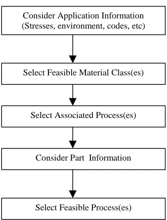
There are several textbooks and handbooks that provide guidelines in material and manufacturing process selection. One is “Engineering Design and Design for Manufacturing a Structured Approach: Text and Reference for Mechanical Engineers” from Dixon and Poli [Dixon 1995] that uses two approaches: the process first approach and the material first approach in solving the material and process selection problems. In the process-first approach, the input is the part information about production volume, size, and shape. Using the part information, feasible processes are identified. Once a process has been selected, the next step is to find a material class that is associated with the selected process. Application information is then applied to identify the final feasible material class(es). In the material-first approach, the search starts with application information. Feasible material classes are determined based on the application information. From the list of feasible material candidates, associated processes are then selected. After considering part information, the final feasible processes are listed. It is stated that both approaches should end up with the same results. The schematic representations of both approaches are shown in Figure 2.2 and Figure 2.3.
16
handbook, the user is required to manually locate relevant information, evaluate it, and compare the alternatives.
Figure 2.2 Process-First Approach Figure 2.3 Material-First Approach
2.1.9 Others
Several other systems have been developed that consider just material selection or process selection. Goel and Chen [Goel 1996] applied the application of neural networks for material selection in engineering design. Parkan and Wu [Parkan 1998] use multiple objective and subjective attributes for process selection. Liao [Liao 1996] uses fuzzy set theory to select materials. All of these systems do not adequately address part description but they provide for matching of the part attributes to material and process requirements. However, they can only match the part attributes with some dynamic capabilities of process domains by introducing advanced techniques such as fuzzy logic and neural network. The research efforts focus primarily on developing tools rather than high-level process planning methodologies.
Consider Part Information (Production volume, size, shape, etc)
Select Feasible Process Type(s)
Select Associated Material Class(es)
Consider Application Information
Select Feasible Material Class(es)
Consider Application Information (Stresses, environment, codes, etc)
Select Feasible Material Class(es)
Select Associated Process(es)
Consider Part Information
Table 2.1 summarizes the extent of the part information details allowed by each of the systems reviewed in this chapter. Table 2.2 summarizes all the design attributes required for the reviewed process selection systems. It should be noted that none of the existing systems, except COMPASS, uses a CAD file as input or creates the part model in a CAD-like environment. However, COMPASS has proposed a framework for a meta planner that will receive CAD files as input to the system. It is not clearly explained how the system extracts information from the CAD file.
Table 2.1Geometry Information Comparison
Features CAMPS MAS EPSS DCA MaMPS CPS COMPAS
S
O
th
ers
Part Volume X X X X X
Part Weight X X X
Shape Descriptor X X X X X X X
Secondary Geometric Features X X X X X X X
Tolerance X X X X X X X X
Surface Finish X X X X X X X X
Wall Thickness X X X
Has Measure of Complexity X X
Check for Uniformity of Wall X X
Use CAD-based environment - - - X
-Use CAD file as input - - - X
SYSTEM DEVELOPER MATERIAL REQUIREMENTS DESIGN REQUIREMENTS Manufacturing Advisory Service
(MAS)
Charles S.Smith, UC at Berkeley 1999, Ph.D Thesis
1. Cost per Pound 2. Yield Strength 3. Density
4. Process Compatibility 5. Thermal Expansion 6. Elastic Modulus 7. Hardness
1. Batch Size
2. Shape : - Prismatic Milling - Surface of Rotation Turning - Planar Sheet Metal Blanking - Thin Walled Injection Molding - Constant Cross Section Extrusion - Draped Free Form Forging - General Freeform Sand Casting 3. Bounding Box
4. Tolerance 5. Surface Finish 6. Wall Thickness 7. Production Rate 8. Setup Time 9. Setup Cost 10. Per part Cost Material and Manufacturing
Process Selection System (MAMPS)
Ronald E. Giachetti 1998 J.of Intelligent Mfg 9,265-276
1. Hardness 2. Stiffness/density 3. Str/density 4. Density 5. Cost/kg
6. Thermal condition 7. Corrosion
1. Undercuts : Yes or No ? 2. Wall Thicknes : Min and Max 3. Overal Dimensions : Length, Width 4. Weight
5. Shape : - Cone axial - hollow axial - prismatic - round flat - rounded box - solid axial - square flat - squared box - tank 6. Surface Finish 7. Tolerance
8. Production Rate : part/ht 9. Production Volume 10. Time to Market : # months CMS Process Selector Esawi, AMK & Ashby M.F. ,
Univ of Cambridge
1. Material Class : - Light Metal - Ferrous - Fine ceramic
1. Process Class :
- Primary, discrete 2. Shape Class:
- Prismatic - Sheet - 3-D 3. Size (kg)
4. Minimum section (mm) 5. Precision (mm) 6. Surface Finish (µm) 7. Batch Size Table 2.2 Summary of Existing Process Selection Systems
SYSTEM DEVELOPER MATERIAL REQUIREMENTS DESIGN REQUIREMENTS
Computer Oriented Materials, Processes and Apparatus Selection System (COMPASS)
Chan, K et al. 1998. J.of Mfg Systems Vol. 17 No.4
Name : 6061T6 aluminum alloy etc.
1. Shape :
- Rotational - Non-Rotational 1. Tolerance
2. Surface Finish 3. Production Volume 4. Bounding Box Computer-aided Design for
Manufacturing Process Selection
Yu, J.-Cheng et al. 1992. J. of Intelligent Mfg, 4, 199-208
1. Mechanical properties: - Stiffness - Hardness - Strength etc. 2. Physical properties:
- Erosion - Resistance - melting temperature etc 1. Shape 2. Bounding Box 3. Weight 4. Tolerance 5. Surface Finish 6. Production Quantity
Computer-aided Process/Material Selection
Shea, C and Dewhurst, P 1989
1. Mechanical Properties 2. Thermal Properties 3. Electrical Properties
1. Shape:
- Depressions - Uniform wall - Uniform cross section - Axis of rotation - Regular cross section - Captured cavity - Enclosed cavity - No draft 2. Size
3. Production parameters Expert Processing Sequence
Selector
Farris, Univ. of Rhode Island 1992, Ph.D Thesis
1. Bounding box
2. Basic shape: rotational and non-rotational 3. Tolerance
4. Surface finish
5. Cross section of the part: - constant
- constant, if some features are ignored - not constant
6. Functional features: - depressions - projections Table 2.2 Summary of Existing Process Selection Systems (continued)
20
2.2 Feature Technology
The review of the major research work in the area of high-level process planning reveals that the systems developed are generally not CAD-based. Even though some are computer-assisted systems, designers are still required to input information manually. For example, the part geometry in Giachetti’s system is described using the following terms:
- Presence of undercut (yes/no)
- Shape: cone axial, hollow axial, prismatic, round flat etc. - Weight (g)
- Wall thickness (cm) - Enclosing envelope
In practice, specifying design attributes manually can be time consuming and subject to error and inaccuracies. In this research, it is of great interest to automate the input procedure related to geometrical features.
Currently, geometric modeling techniques such as Constructive Solid Geometry (CSG) and Boundary Representation (B-Rep) are widely used in solid CAD systems. However, the current geometric modeling systems represent geometry models at a low, very detailed level. For example, B-rep models are described in terms of edges, faces, curves, etc. CSG models are described in terms of solid primitives and Boolean set operators. Consequently, it can be difficult to integrate CAD with high-level process planning.
One advantage of the feature recognition approach is that the designers can work directly on the current CAD system. However, in order to get information from the CAD model, feature recognition algorithms need to be developed, and this is not an easy task. Even recognition of a simple feature may require a complex algorithm. So the main deficiency of the feature recognition approach is that it can be a time consuming process due to the complexity of algorithms and the need for extensive search to find the information from a CAD model. On the other hand, one benefit of using the design by feature approach is that features can capture the functional intent on which a designer’s activity is based within its geometry-based representation [Cunningham 1988, Dong 1990]. In feature-based modeling, a “cylindrical hole” feature has a much clearer meaning than just a “cylinder” primitive in CSG. Also feature-based modeling has become more popular in the field of design and automation since it can facilitate high-level communications between design and manufacturing systems [Shah 1996]. However, the design by feature approach limits designers’ ability to create complex parts due to the limited number of predefined features that can be stored in the feature library.
The term “feature” has been used in many different ways and for different purposes. Since form features are the most commonly used types of features in process-planning systems, when talking about features, one usually means form features. There is no single formal definition of a “feature”. The various definitions of a feature are summarized in Table 2.3. However, the following definition perhaps can represent the general definition of a “feature”:
“A feature is a partial form or a product characteristic that is considered as a unit and that has a semantic meaning in design, process planning, manufacture, cost estimation or other engineering discipline” [Wierda 1991].
22
Table 2.3 Definition of Features [Kim 1994]
Definition Reference
“a specific geometric configuration formed on the surface, edge, or corner of a workpiece intended to modify outward appearances or to aid in achieving a given function”
[CAM-1 1981]
“a geometric form or entity whose presence or dimensions are required to perform at least one CIM function, and whose availability as a primitive permits the design process to occur
[Luby 1986]
“a single face or set of connected faces which has certain characteristic combinations of topology and geometry”
[Sakurai 1988]
“any geometric form or entity that is used in reasoning in one or more design or manufacturing activities”
[Cunningham 1988]
“a region of interest in a part model” [Wilson 1988]
“a part of a formed object that is physically differentiable from the rest of the object and performs certain functions”
[Gadh 1989]
“objects to which problem-solving knowledge such as process planning will refer. They serve to classify geometric and topological patterns as being manufacturable by one process or another”
[Hummel 1989]
“a geometrical form and a set of specifications for which a process planning process exists and this process is almost independent of the other features of the part”
[Tsang 1989]
“a primitive in a high-level language or representation scheme for defining mechanical parts”
[Requicha 1989]
“regions of a part having some manufacturing significance in the context of machining”
[Joshi 1988]
“recurring patterns or information related to a part’s description” [Shah 1989] “an abstraction of lower-level design information” [Pinilla 1989] “the modeling entities that satisfy the specific needs of various
design disciplines”
[Zamanian 1991]
“any geometrical attribute that is necessary for the part to fulfill its intended function”
[Boothroyd 1992]
“higher level entities that model the correspondence between design information and manufacturing activities”
[Regli 1995]
• A feature is a physical constituent of a part.
• A feature is mappable to a generic shape.
• A feature has engineering significance.
As previously mentioned, there are two main approaches that are currently employed in feature-based modeling:
(1) Feature recognition. A geometric model is created first, then a computer program processes the resulting model to automatically identify features.
(2) Design by features. The geometric model of part is created directly in terms of features.
2.2.1 Feature recognition
Feature recognition is a post-processing approach; meaning that some procedures need to be applied to the CAD model in order to recognize its features. This is the first generation technique developed in feature technology. With this approach, designers can still work with the existing CAD systems. A significant amount of work has been done in feature recognition, and the approaches can be categorized into three groups as follows:
1. Ruled-based approaches 2. Graph-based approaches
3. Volume decomposition approaches
2.2.1.1 Rule-based recognition approach
In this approach, sets of rules are written to define features. Feature recognition is done by matching certain patterns and relationships to the rules of features. The general form of rules can take the following form:
If (A1, A2, A3, …,An ) then F
Where A1, A2, A3, …,An are conditions that define the feature F.
24
If a hole entrance exists and a cylindrical face is adjacent to the entrance and there is a bottom to the cylinder, Then
The entrance face, cylindrical face and bottom form a cylindrical hole [Chan 1994]
The rule above still needs to be elaborated in more details, at a lower level. The CAD system still needs knowledge of how to define a hole entrance, a cylindrical face, its position to the entrance, and whether or not there is a bottom to the cylinder. The geometric knowledge of the CAD systems is normally due to its storing of low-level information based on B-rep such as vertices, edges, and faces.
Rule-based recognition is useful in classifying secondary information for feature recognition, but is inadequate in defining feature topology and separating intersecting features [Chen 1998]. The apparent disadvantage of this technique is that it requires a large number of rules since each rule looks only for one specific feature.
2.2.1.2 Graph-based recognition approach
With the graph-based approach, the topology of the part is converted into edge-face graphs, which represent the adjacency relationship of the bounding suredge-face in the form of connecting nodes and arcs. The graph-based approach matches the predefined feature graphs to sub-graphs from the part. The advantage of the graph-based approach is that the well-established techniques of graph algorithms can be adapted to feature based modeling [Shah 1995]. The disadvantages of this approach are as follows:
(1) The graph matching ensures only topological equality. (2) The matching algorithm is NP complete.
(3) Intersecting features may bring some problems to this approach since feature topologies are altered.
2.2.1.3 Volume decomposition approach
three-dimensional volumes. The convex hull decomposition was originally developed by Woo [Woo 1982]. This approach uses the convex hull of the part volume to subtract the part volume, and then uses the new convex hull of the resulting volume to subtract the resulting volume until a null volume is met. The resulting volumes are known as alternating sum of volumes (ASV), from which convex components, or sub-volumes, can be generated in the form of a DSG (Destructive Solid Geometry) tree. The main problem with Woo’s approach is that it requires a convex hull to start so that it may lead to the problem of non-convergence in some cases.
Overall, since feature recognition approach is a post-processing approach, it allows different CAD systems as input data. This is perhaps the main advantage of feature recognition. Recognition procedures are used to obtain the recognized procedures. However, the approach may lead to infeasible results due to:
1. Imprecise or incorrect geometry in the designed part due to a designer’s mistake. For example, in defining a solid axial for part shape, all cylindrical features must share the same axis of revolution. But, if there is at least one cylindrical feature shifted a small amount from the axis of revolution, the part shape becomes undefined.
2. Incomplete feature recognition algorithms. In some situations, there could be some features that cannot be recognized, because those features are not predefined. In some cases, recognition algorithms fail to recognize due to the interacting features.
2.2.2 Design by Feature
26
However, the design by feature approach itself has deficiencies. The main weaknesses of this approach are that, feature recognition algorithms are still required, since features are very application dependent. The other weakness, practically speaking, is that this approach makes it difficult for designers to create complex parts.
2.2.3 Feature-Based Design and Process Planning
The topic of feature-based design has been investigated by many researchers in the field of CAD/CAPP integration. Most of the work has focused on developing feature-based process planning systems. Until now, automated feature recognition has been the most common approach used to extract manufacturing features from CAD systems. Almost all feature-based process planning systems that have been developed to date focus primarily on machining processes. Consequently, when a researcher refers to the process of extracting manufacturing features from the CAD system, he or she is usually referring to machining features.
As previously discussed, a problem of feature recognition is that it needs to infer a lot of information from the CAD product model and usually at a high cost when this information has already been generated during the design process [Salomons 1993]. Also, technical information is unavailable in the source geometric database and, consequently, the user has to obtain the information from other sources [Xiang 2000].
features. HutCAPP is a similar system [Mäntylä 1989] that provides a facility for changing the feature specification of the part.
One major drawback of the design by manufacturing feature approach is that only negative features (holes and other features that subtract material from base) are available. Positive features such as bosses, ribs and other projection features are difficult to represent directly with machining operations. Therefore, they must be mapped to equivalent material removal features [Shah 1994].
Since a high-level process planning system should cover a wide spectrum of process domains, if the design by feature approach is adopted, then the main challenge becomes how to establish a correct and complete transformation from the primary design feature representation to the secondary manufacturing feature representation that is required for the application [Cunningham 88]. Applications here may include process planning, cost analysis and manufacturability.
2.3 Summary of the Existing High-Level Process Planning Systems
The review of the existing research related to high-level process planning systems points out that virtually none of the systems allow CAD-based input. All material and design attributes are defined manually via text-based methods. In defining the shape of the part, designers need to select a single overall description of the part. In doing so, there are three inputs that help designers make a selection: a textual description of what kind of shapes fit into the category, sample illustrations of typical parts, and a list of components that would fall into each category [Smith 1999]. Unfortunately, classification and coding systems, which use a similar method to describe part geometry, have long suffered from problems of ambiguity and misclassification. Simply put, it is not easy to describe complex geometries with a small set of textual descriptions.
28
part design by just adding, deleting and manipulating features, a feature-based environment will significantly help the designer create preliminary designs with an emphasis on ease of manufacturability.
In practice, determining the cost of making a part at the early stages of design is more crucial than low-level process planning. Most of the reviewed existing systems do not provide early cost estimates. For designers, early information on the cost of the part is very important in determining whether or not a company should proceed to the detailed design stage. In the existing systems, the cost estimation is non-existent or difficult to implement. Usually the design attributes associated with the processes are manually input, which is time consuming and subject to human error. For example, in defining the complexity of the part shape of an injection molded part, the reviewed systems may detect whether or not there is an undercut. However, in the cost analysis for injection molding process, not only is the presence of an undercut important, but also the selection of the parting plane, the number of undercuts and the types of undercut (i.e. internal or external) are crucial. In order to obtain a good early cost estimate, feature information from the part needs to be available. In some net shape manufacturing processes such as injection molding and die-casting, the complexity of the part’s shape will significantly affect the manufacturing cost, in particular, the tooling cost. So, it is believed that a good cost estimate can only be obtained if the part shape can be well described.
3. R
ESEARCHO
BJECTIVESIn each of the reviewed process selection systems that have been discussed in Chapter 2, users or designers manually input the material and design attributes [Yu 1993, Farris 1992, Giachetti 1998, Eshawi 1998, Smith 1999]. The candidate processes are then obtained by matching all the design attributes with the process capabilities of each process domain. Some systems, such as the Expert Process Sequence Selector [Farris 1992], Manufacturing Advisory Service [Smith 1999] and Material and Manufacturing Process Selector [Giachetti 1998] use advanced decision-making processes such as fuzzy logic to select and rank the candidate materials and/or processes. These systems, however, do have drawbacks. They are not CAD-based systems, and they provide very limited support for downstream applications such as cost estimation.
The main objective of this research has been to develop a FEature-Based Design And Process Planning (FEBDAPP) system that helps designers improve their designs by providing manufacturing advice while they are in the early stages of the design process. In order to achieve this goal, the following specific objectives were set for this research:
1. Develop a hybrid system incorporating design by feature and feature recognition approaches capable of reducing the complexity of feature recognition algorithms without sacrificing flexibility in creating a part design.
2. Develop a comprehensive set of B-Rep based feature-mapping procedures that are capable of transforming the primary part representation into application-based features. The application-based features are basically design parameters used in applications, in this case, the high-level process planning system.
3. Develop CAD-based procedures and interface software capable of interfacing the current CAD systems and the relational database management system used in the existing high-level process planning system.
30
4. F
RAMEWORK OF THEF
EBDAPPS
YSTEMIn this research, a CAD-based interface that extracts or creates design information that is needed for a high-level process planning system has been developed. It implements functions that utilize the feature information to provide designers with information on such factors as process selection and cost estimation that are valuable for an efficient design process. In order to create an interface that is capable of providing this kind of information, a hybrid system of feature recognition and design by feature approaches has been proposed and implemented in this research.
Figure 4.1 shows the overall framework of the Feature-Based Design and Process Planning (FEBDAPP) system. As shown in the figure, the existing high-level process planning systems have focused primarily on process selection. Although they are computer-aided systems, most of them call for manual input of design attributes and are not CAD-based. In order to develop an intelligent CAD-based system that can be integrated with downstream applications, this research focuses on (1) part creation, (2) feature mapping, and (3) application development. In this research, that is a high-level process planning and cost estimation system.
In part creation, designers use either predefined features or a sketch in creating a part. When dealing with the most frequently used parts, the design by features approach will be more favorable, since feature information can be directly derived. However, designers will frequently have to create more complex parts from sketches for which predefined features cannot be used. Even though the design by feature approach tries to eliminate the task of feature recognition, a search algorithm is still needed for certain information that is required for downstream applications.
In this research, a hybrid system of design by feature and feature recognition approaches is employed for the following reasons:
Figure 4.1 The Framework of the FEBDAPP System
Designer Solid model
Predefined features Secondary Feature Representation APPLICATION MODULES Process Selection Cost Estimation Preliminary Manufacturability Etc. Manually Text-based Input Existing Process Selection Systems Feature Mapping ToolBox Application rules database
Application-based feature 1
Application-based feature 2
. .
Application-based featuren
2. Even though a whole part is built from predefined features, the feature recognition approach is still needed for recognizing application-dependent features, such as undercuts in injection molding and die-casting and part shape in process selection.
This research is intended to bring together the advantages of both design by feature and feature recognition approaches. It should be noted here that the feature recognition approach implemented in this dissertation is different from what is found in existing research on extracting machining feature using the feature recognition approach. It is of great interest in this research to focus on net-shape manufacturing process domains. For machined parts, the major challenge lies in determining how to convert the solid model or design features into machining features, in particular how to recognize and extract the interacting feature and to map the positive feature into the sequence of machining features that need to be taken away from the stock.
In high-level process planning systems, there are decision factors that need to be defined. They can be classified as related to geometrical features, technological features, and production features [Giachetti 1998]. Since this research is intended to select the candidate primary processes for a given part, the focus is on geometrical features. Geometrical features here include part shape, wall thickness, part size, weight, and undercuts. Technological features, which include surface finish and tolerance, are important factors, but they are not driving factors for primary processes. For example, even though a part requires a tight tolerance and fine surface finish, sand casting can be a candidate primary process. Although sand casting results in poor surface finish, an improved finish can be obtained through secondary processes. Production features, which include the production volume, are also not driving factors for primary process selection.
34
features are basically design parameters that are required for applications such as process selection, manufacturability analysis, and cost estimation. It is of great interest to develop a toolbox that contains procedures for the mapping process. It is intended that these tools are generic enough so that they can be used for many downstream applications. Both feature mapping and application-based features will be discussed in detail in the next section.
This research has aimed at developing a framework for a feature-based high-level process planning system. As discussed in Chapter 1, the main interest at the conceptual stage is to find the candidate processes and cost estimates. For demonstration purposes, Giachetti’s high-level process planning system is adopted to select the candidate processes. Once the processes are selected, the next task is to find the cost. Tooling cost estimation procedures for net-shape manufacturing processes such as injection molding and die-casting have been developed and are presented in Chapter 5.
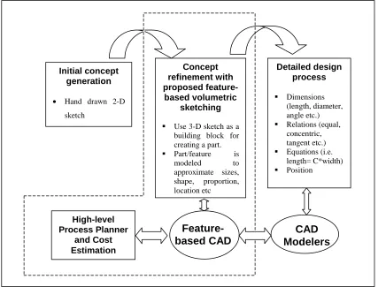
Before proceeding further, it is necessary to look at the proposed product development process as shown in Figure 4.2. Instead of using a hand-drawn sketch, a 3-D volumetric feature is used for building a part. Due to the nature of design at the preliminary stage, a part is created to the approximate size, shape, position, location etc. Part creation is done in a feature-based CAD environment. The primary part representation in a CAD modeler then becomes an input to the high-level process planning system. Once a candidate process is selected, the associated cost estimate can be determined, and the detailed design process can begin. In the detailed design process, the CAD model from conceptual design stage can be used and the process needs not start from scratch.
4.1 Concept of a Hybrid System
a CAD system becomes a common design tool, the CAD system may also be used at the conceptual design stage.
Figure 4.2 Proposed product development process
It is argued that the design by feature approach is more appropriate for the detailed design stage, since it is assumed that a process domain is selected prior to this stage. Once a process is known, it becomes apparent that designers tend to choose features that are “compatible” with the process domain. The term “compatible” can be interpreted as easy to manufacture. So, by employing the design by feature approach at the detailed design stage, designers can avoid the use of features that may be difficult to manufacture. Nevertheless, the design by feature approach itself can be applied at the conceptual stage. Even at the conceptual stage, designers have already in their mind the “standardized”, “familiar”, or “known” features that will be used.
Initial concept generation
• Hand drawn 2-D sketch Concept refinement with proposed feature-based volumetric sketching
Use 3-D sketch as a building block for creating a part.
36
In a design by feature system, a part P is represented in terms of features, F1,..,n as
follows:
n F F
F F
P= 1U 2 U 3LLU
Each feature F1, F2, …Fn has its own attributes. These attributes can be names of features, feature types, surface finishes, tolerances etc. So, once a part is created, all these features can be directly obtained. To illustrate this idea, consider the following simple rotational part consisting of two cylindrical bosses and one cylindrical hole as seen in Figure 4.3.
Figure 4.3 A simple rotational part
The feature set for the part, P above can be represented as follows:
F1(solid cylinder)
F2(solid cylinder)
F3 (blind hole)
F1{cylindrical boss, cylinder 1, fine finish, tight tolerance etc.}
F2 {cylindrical boss, cylinder 2, medium finish, good tolerance,
etc}
F3 {cylindrical blind hole, blind hole 1, fair finish, good tolerance
All information about the types of features (i.e. cylindrical boss and blind hole), surface information (i.e. fine, fair), and tolerance information (i.e. tight, good) can be easily obtained, since they are already attached and stored in the feature library. On the other hand, when a part is created in a non-design by feature CAD environment, the part is represented at the microscopic level, i.e. points, edges, and faces. In order to recognize the features, feature recognition procedures need to be developed. Chapter 2 has discussed several techniques that have been developed in feature recognition. Pros and cons to feature recognition have also been discussed previously.
The hybrid system used in this research is intended to synergize both approaches so that the shortcomings of each approach can be minimized. This system is essentially an improved “pure” design by feature system such that a part may not necessarily be built from predefined features. In some circumstances, when designers have to deal with a novel feature that is not listed in the feature library, they must build it from sketch(es). The feature recognition approach is then employed to recognize this unknown feature.
Adopting the concept of the design by feature approach, volumetric features are used in creating a part instead of a 2-D sketch that is commonly used in practice. Examples of volumetric features are boxes, cylinders, slots, pockets, ribs, etc. Unlike the creation of detailed designs on most CAD modelers, in the volumetric sketching approach, features are drawn to approximate size, shape, and location.
Several CAD systems such as SolidWorks, Pro/Engineer, and Unigraphics already employ the design by features approach. However, these systems still have some limitations as follows:
1. The design by feature approach facilitated in the existing systems is primarily suitable for only orthogonal parts. New features must be placed orthogonally to the planar surface of only the existing feature(s).
2. Even though an orthogonal part has been created, the feature recognition approach is still needed since some features are application dependent.
38
approach is a pre-processing approach. Predefined features are created and stored in the feature library before a part model is created. In this research, it is of great interest to do both pre and post processing approaches. By doing so, the designer still has the flexibility to create non-standardized features. At the same time, feature recognition procedures need not be executed for most frequently used parts.
4.2 Part Creation
In the existing high level process planning systems, it is assumed that the designer has already completed the part design with all the design attributes before he or she starts working with the process selection system. These design attributes, which include materials and processes attributes, are manually entered into the system. One of the specific objectives of this research is to simplify and automate this input procedure, in particular the input of geometrical features that include part shape, wall thickness, part size, undercuts, and weight.
Instead of prompting a designer with a set of questions to describe a part, this research has developed a procedure for the part to be represented in terms of volumetric design features. The developed system allows designers to create a part design by adding and manipulating features. Compared to typical text-based classification, the feature-based modeling approach has the following advantages:
1. It is feasible to derive information required for downstream applications.
2. Concurrent performance of both design synthesis and design evaluation using the feature-based volumetric sketching for engineering design results in a faster product development cycle.
![Figure 1.1 Typical Steps in Concurrent Engineering [Boothroyd 1995]](https://thumb-us.123doks.com/thumbv2/123dok_us/1456388.1178446/14.612.148.524.136.562/figure-typical-steps-concurrent-engineering-boothroyd.webp)


![Figure 4.12 MaMPS’ architecture [Giachetti 1998]](https://thumb-us.123doks.com/thumbv2/123dok_us/1456388.1178446/69.612.116.544.73.407/figure-mamps-architecture-giachetti.webp)