University of Windsor University of Windsor
Scholarship at UWindsor
Scholarship at UWindsor
Electronic Theses and Dissertations Theses, Dissertations, and Major Papers
4-14-2017
NOVEL TECHNIQUES FOR TORQUE RIPPLE MODELING AND
NOVEL TECHNIQUES FOR TORQUE RIPPLE MODELING AND
MINIMIZATION IN PERMANENT MAGNET MACHINES
MINIMIZATION IN PERMANENT MAGNET MACHINES
Chunyan Lai
University of Windsor
Follow this and additional works at: https://scholar.uwindsor.ca/etd
Recommended Citation Recommended Citation
Lai, Chunyan, "NOVEL TECHNIQUES FOR TORQUE RIPPLE MODELING AND MINIMIZATION IN PERMANENT MAGNET MACHINES" (2017). Electronic Theses and Dissertations. 5946.
https://scholar.uwindsor.ca/etd/5946
This online database contains the full-text of PhD dissertations and Masters’ theses of University of Windsor students from 1954 forward. These documents are made available for personal study and research purposes only, in accordance with the Canadian Copyright Act and the Creative Commons license—CC BY-NC-ND (Attribution, Non-Commercial, No Derivative Works). Under this license, works must always be attributed to the copyright holder (original author), cannot be used for any commercial purposes, and may not be altered. Any other use would require the permission of the copyright holder. Students may inquire about withdrawing their dissertation and/or thesis from this database. For additional inquiries, please contact the repository administrator via email
N
OVELT
ECHNIQUES FORT
ORQUER
IPPLEM
ODELING ANDM
INIMIZATION INP
ERMANENTM
AGNETM
ACHINESBy
Chunyan Lai
A Dissertation
Submitted to the Faculty of Graduate Studies
through the Department of Electrical & Computer Engineering in Partial Fulfillment of the Requirements for
the Degree of Doctor of Philosophy at the University of Windsor
Windsor, Ontario, Canada
2017
Novel Techniques for Torque Ripple Modeling and Minimization in
Permanent Magnet Machines
by Chunyan Lai
APPROVED BY:
______________________________________________ L. Lopes, External Examiner
Concordia University
______________________________________________
B. Minaker
Department of Mechanical, Automotive & Materials Engineering
______________________________________________
M. Saif
Department of Electrical & Computer Engineering
______________________________________________
J. Wu
Department of Electrical & Computer Engineering
______________________________________________
K. Mukherjee, Special Committee Member Department of Electrical Engineering
Indian Institute of Engineering Science and Technology, Shibpur, India
______________________________________________
N. Kar, Advisor
Department of Electrical & Computer Engineering
iii
DECLARATION OF CO-AUTHORSHIP / PREVIOUS PUBLICATIONS
I hereby declare that this dissertation incorporates material that is result of joint research, as follows: This dissertation includes the outcome of publications co-authored with Dr. Guodong Feng, Dr. K. Lakshmi Varaha Iyer and Dr. Narayan Kar from University of Windsor, Dr. Kaushik Mukherjee from Indian Institute of Engineering Science and Technology, and Dr. Voiko Loukanov from our industrial partner D&V Electronics. In all cases, only primary contributions of the author towards these publications are included in this dissertation. The contribution of co-authors was primarily the guidance and assistance in experimentation, data analysis, and manuscript review and improvement.
I am aware of the University of Windsor Senate Policy on Authorship and I certify that I have properly acknowledged the contribution of other researchers on my dissertation and have obtained written permission from each of the co-author(s) to include the above material(s) in my dissertation. I certify that, with the above qualification, this dissertation, and the research to which it refers, is the product of my own work.
This dissertation includes selected sections and extended work of research conducted in eight original papers that have been published / submitted for publication in peer reviewed IEEE Transactions and international conferences, as follows:
Dissertation
Chapters Publication title/full citation
Publication status
Chapters 2&3
C. Lai, G. Feng, K. L. V. Iyer, K. Mukherjee and N. C. Kar, "Genetic Algorithm based Current Optimization for Torque Ripple Reduction of Interior PMSMs," in Proc. XXII International Conf. on Electrical Machines, Lausanne, Switzerland, pp.1050-1056, 2016.
Published
Chapters 2&3
C. Lai, G. Feng, K. L. V. Iyer, K. Mukherjee, and N. C. Kar, "Genetic Algorithm based Current Optimization for Torque Ripple Reduction of Interior PMSMs," IEEE Transactions on Industrial Applications, Oct. 2016.
Under 2nd Round of
iv Chapters
2&3
G. Feng, C. Lai, K. L. V. Iyer and N. C. Kar, "Torque Ripple Modeling and Minimization for PMSM Drives with Consideration of Magnet Temperature Variation," in Proc. XXII International Conf. on Electrical Machines, Lausanne, Switzerland, pp. 612-618, 2016.
Published
Chapters 2&3
C. Lai, G. Feng, K. Mukherjee, V. Loukanov and N. C. Kar, "Torque Ripple Modeling and Minimization for Interior PMSM Considering Magnetic Saturation," IEEE Transactions on Power Electronics, Aug. 2016.
Under 2nd Round of
Review
Chapter 3
G. Feng, C. Lai, and N. C. Kar, "An Analytical Solution to Optimal Stator Current Design for PMSM Torque Ripple Minimization with Minimal Machine Losses," IEEE Transactions on Industrial Electronics, Oct. 2016.
Under Revision
Chapter 4
C. Lai, G. Feng, K. Mukherjee, V. Loukanov and N. C. Kar, "Torque Ripple Minimization for Interior PMSM with Consideration of Magnetic Saturation Incorporating On-Line Parameter Identification," IEEE Transactions on Magnetics, Oct. 2016.
In Press
Chapter 4
C. Lai, G. Feng, K. Mukherjee, and N. C. Kar, "Investigations of the Influence of PMSM Parameter Variations in Optimal Stator Current Design for Torque Ripple Minimization," IEEE Transactions on Energy Conversion, Oct. 2016.
Under 2nd Round of
Review
Chapter 5
G. Feng, C. Lai, N. C. Kar, "A Closed-Loop Fuzzy Logic based Current Controller for PMSM Torque Ripple Minimization Using the Magnitude of Speed Harmonic as the Feedback Control Signal," IEEE Transactions on Industrial Electronics, 2016.
v
I hereby certify that I have obtained a written permission from the copyright owners to include the above published materials in my dissertation. I certify that the above material describes work completed during my registration as graduate student at the University of Windsor. I certify for the materials that I am one of the co-authors, only sections with my contribution are included.
I certify that, to the best of my knowledge, my thesis does not infringe upon anyone’s copyright nor violate any proprietary rights and that any ideas, techniques, quotations, or any other material from the work of other people included in my thesis, published or otherwise, are fully acknowledged in accordance with the standard referencing practices. Furthermore, to the extent that I have included copyrighted material that surpasses the bounds of fair dealing within the meaning of the Canada Copyright Act, I certify that I have obtained a written permission from the copyright owner(s) to include such material(s) in my thesis and have included copies of such copyright clearances to my appendix.
vi
ABSTRACT
This thesis investigates torque ripple modeling and minimization techniques for permanent magnet (PM) machines to achieve high-performance and reliable machine drive for practical industrial and consumer applications. At first, a comprehensive torque ripple model is proposed, in which the torque ripples resulting from the spatial harmonics of magnet flux, the time harmonics of stator currents and the cogging torque are included. Since the proposed torque ripple model involves machine operation dependent parameters, the effects of parameter variation on PM machine torque ripple modeling are investigated, to improve the accuracy and robustness of the proposed model.
The key to torque ripple minimization is to determine an optimal stator current that can generate an extra torque ripple to cancel the torque ripple produced by the PM machine. Based on the proposed torque ripple model, a genetic algorithm (GA) based statorcurrent optimization approach is proposed for torque ripple minimization, in which the GA is applied to optimize the stator currents to achieve the objectives of: 1) minimizing the peak-to-peak torque ripple; 2) minimizing the rms value of the stator current/machine losses induced by stator current; and 3) maximizing the average torque component produced by the injected harmonic currents. Then, an analytical solution to the optimal stator current design is developed from the proposed model, which can significantly reduce the computation time in finding the optimal currents for torque ripple minimization. Thus, this analytical solution is applicable for torque ripple minimization under both transient and steady states of a PM machine.
vii
harmonic for feedback stator current control for torque ripple minimization in PM machines. Therefore, a closed-loop fuzzy logic based current controller using the speed harmonic as the feedback control signal is proposed for PM machine torque ripple minimization. The speed harmonic is obtained from machine speed measurement, so the proposed approach does not require accurate machine parameters and is not influenced by the nonlinearity of the machine and the inverter.
viii
DEDICATION
ix
ACKNOWLEDGEMENTS
First of all, my sincere thanks goes to my advisor, Dr. Narayan Kar, for providing me enthusiastic guidance, full support and many resources for my study and research in the past four years in the Ph.D. program. He inspired me with confidence, and encouraged me to be a leader in research. Dr. Kar is gracious to us as a friend and family; he takes care of us in more than our research.
My sincere thanks also goes to Dr. Kaushik Mukherjee, who has guided me in a co-supervisory role during my Ph.D. study. He shares valuable research experience and ideas with me in conducting research, and he gives constructive comments and suggestions on the technical contents of research work I am conducting.
I would like to express my gratitude towards Dr. Mehrdad Saif, Dr. Bruce Minaker, Dr. Jonathan Wu and Dr. Luiz A.C. Lopes for agreeing to serve on my committee, attending my seminars and defense, and providing valuable suggestions so that I can improve the quality of this dissertation.
I am thankful to my lab colleagues and friends who have been of great support in my study, professional activities and life. Starting from my dear best friend Dr. Xiaomin Lu, who introduced me into this program, she helps me not only in my study, but also takes care of me in daily life. My research group leader, Dr. Guodong Feng, has provided great technical guidance towards my research work, including theoretical and experimental investigations. Other fellow lab members, such as Dr. Lakshmi Varaha Iyer, Junxi Cai and Jiangbo Tian, in the Centre for Hybrid Research and Green Energy (CHARGE), have given me friendly support and help whenever needed.
x
TABLE OF CONTENTS
DECLARATION OF Co-authorship / PREVIOUS PUBLICATIONS... iii
ABSTRACT ... vi
DEDICATION ... viii
ACKNOWLEDGEMENTS ... ix
LIST OF TABLES ... xiii
LIST OF FIGURES ... xiv
NOMENCLATURE ... xviii
Chapter 1 INTRODUCTIONS ...1
1.1 Overview and Motivations ...1
1.2 Literature Review ...6
1.2.1 Machine Design Techniques for Torque Ripple Reduction ...7
1.2.2 Machine Control Techniques for Torque Ripple Reduction ...10
1.3 Research Objective ...13
1.4 Research Contributions ...14
1.5 Dissertation Layout ...16
Chapter 2 COMPREHENSIVE TORQUE RIPPLE MODELING ...17
2.1 Introduction ...17
2.2 Generalized Torque Ripple Modeling ...19
2.3 Torque Ripple Modeling Considering Magnet Temperature Variation ...23
2.3.1 Magnet Flux Analysis under Different Magnet Temperatures ...25
2.3.2 Magnet Flux Temperature Model ...27
2.3.3 Torque Ripple Model Considering Magnet Temperature Variation ...30
xi
2.5 Validations of the Proposed Torque Ripple Models ...33
2.6 Summary ...38
Chapter 3 FEED-FORWARD BASED TORQUE RIPPLE MINIMIZATION ...39
3.1 Introduction ...39
3.2 GA based Stator Current Optimization for Torque Ripple Minimization ...40
3.2.1 Objective Functions for Stator Current Optimization ...40
3.2.2 GA based Optimal Current Design ...42
3.2.3 Numerical Investigations ...43
3.2.4 Experimental Test and Results for Torque Ripple Minimization...45
3.3 Analytical Solution for PM Machine Torque Ripple Minimization ...48
3.3.1 Finding an Analytical Solution for Torque Ripple Minimization ...48
3.3.2 Simulations Studies of Applying the Analytical Solution for PM Machine Torque Ripple Minimization ...52
3.3.3 Experimental Studies on PM Machine Torque Ripple Minimization Employing the Analytical Solution ...55
3.4 Summary ...59
Chapter 4 INVESTIGATION OF THE INFLUENCE OF PARAMETER VARIATION ON TORQUE RIPPLE MINIMIZATION ...60
4.1 Introduction ...60
4.2 Investigation of PM Machine Parameter Variation ...61
4.2.1 Investigation of Magnet Flux Variation ...61
4.2.2 Investigation of Inductance Variation ...62
4.3 Theoretical Analysis of Parameter Variation on Optimal Stator Current Design for Torque Ripple Minimization ...65
4.3.1 Investigation of the Influence from Magnet Flux Variation ...65
4.3.2 Investigation of the Influence from Inductance Variation ...66
4.3.3 Investigation of the Influence from Cogging Torque Measurement Error ...67
xii
4.4.1 Torque Ripples Resulting from Magnet Flux Variation ...68
4.4.2 Torque Ripples Resulting from Inductance Variation ...70
4.4.3 Torque Ripples Resulting from Magnet Flux and Inductance Variations ...70
4.5 Experimental Studies...72
4.5.1 Torque Ripple Analysis Considering Magnet Flux Variation ...72
4.5.2 Torque Ripple Analysis Considering Inductance Variation ...74
4.6 Summary and Discussions ...75
Chapter 5 FEEDBACK BASED TORQUE RIPPLE MINIMIZATION ...76
5.1 Introduction ...76
5.2 Relation between Torque Harmonic and Speed Harmonic of the Same Order ...77
5.3 Closed-Loop Fuzzy-Logic Based Current Control for Torque Ripple Minimization79 5.4 Experimental Investigations ...85
5.4.1 Investigations on the Fuzzy Control Rule of Current Phase Angle ...87
5.4.2 Performance Analysis with Different Control Gains ...92
5.4.3 Performance Analysis under Different Loading Conditions ...93
5.4.4 Performance Analysis under Different Operating Speeds ...95
5.5 Discussions and Summary ...97
Chapter 6 DISCUSSIONS AND CONCLUSIONS ...98
BIBLIOGRAPHY ...100
APPENDICES ...108
Appendix A: Preliminaries on PM Machine Modeling ...108
Appendix B: Detailed Steps on Torque Ripple Modeling ...111
Appendix C: Permissions for Using Publication ...113
xiii
LIST OF TABLES
Table 1-1: Electric Propulsion System Evaluation [9] ... 2
Table 2-1. The Parameters of the IPM Machine Obtained from FEA ... 18
Table 4-1: The kth Torque Harmonic Induced by Machine Parameter Variation... 67
Table 5-1: Experimental Setups and Explanations ... 88
Table 5-2: Optimal Harmonic Current at Different Speeds ... 96
xiv
LIST OF FIGURES
Figure 1-1. Instantaneous torque waveforms obtained from the electromagnetic model of
a SPM machine under sinusoidal current excitation at different rotor positions [13]. ... 3
Figure 1-2. Overall PM machine architectures [7]. (a) SPM machine. (b) IPM machine. . 4
Figure 1-3. Design of the IPM machine. (a) 2D FEA model. (b) Rotor and stator. ... 4
Figure 1-4. Torque waveform under 11 A rms/phase current excitation at 100 RPM. ... 5
Figure 1-5. Three-phase stator currents of 11 A rms/phase used in the FEA. ... 5
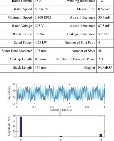
Figure 2-1. Measured shaft torque of the IPM machine at 100 RPM operation. (a) Torque waveform. (b) Dominant torque components obtained from FFT. ... 18
Figure 2-2. The measured three-phase currents of the IPM machine at 100 RPM. ... 19
Figure 2-3. Torque measurement setup for testing the proposed torque ripple minimization approach. ... 19
Figure 2-4. Apparatus for temperature measurement. ... 24
Figure 2-5. Shaft torque measured at 25℃, 45℃ and 65℃, respectively. ... 24
Figure 2-6. The dominant torque components at 25℃, 45℃ and 65℃. ... 24
Figure 2-7. The back-EMF test results at 25℃. (a) Three-phase voltage waveforms in CH1-CH3 and rotor mechanical position indicated in CH4. (b) Harmonic components of one phase voltage. ... 26
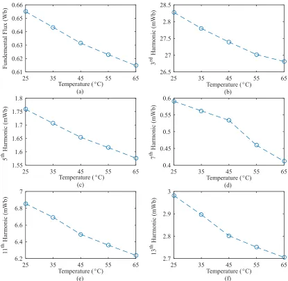
Figure 2-8. The magnetic flux components obtained from back-EMF tests at different magnet temperatures. (a) Fundamental. (b) 3rd harmonic. (c) 5th harmonic. (d) 7th harmonic. (e) 11th harmonic. (f) 13th harmonic. ... 28
Figure 2-9. Inductance values of the test PM machine at different loading conditions under MTPA control. ... 32
Figure 2-10. Cogging torque of the IPM machine obtained from FEA. (a) Cogging torque waveform. (b) Harmonic components in the cogging torque. ... 34
Figure 2-11. The dq-axis magnet flux of the IPM machine obtained from FEA. (a) Flux waveforms. (b) Flux harmonic components. ... 34
xv
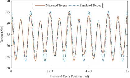
Figure 2-13. The simulated torque waveform using the proposed generalized torque model against the measured torque waveform of the protoptyped IPM machine under full
load condition at 25℃. ... 36
Figure 2-14. The simulated output torques of the IPM machine by considering and neglecting magnet temperature, and the measured shaft torque at 65℃. (a) Waveforms. (b) Torque harmonic components. ... 37
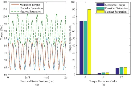
Figure 2-15. The simulated output torques of the IPM machine by considering and neglecting magnetic saturation, and the measured shaft torque at 25℃. (a) Waveforms. (b) Torque harmonic components. ... 37
Figure 3-1. Diagram of the GA based torque ripple minimization. ... 40
Figure 3-2. Values of the objective functions g1, g2 and g3 during GA optimization for torque ripple minimization at the rated condition. ... 44
Figure 3-3. Optimal dq-axis currents obtained from the proposed method and the compared method that considers the harmonic current phase angle as a constant. ... 45
Figure 3-4. The output torques with and without harmonic current compensation. ... 45
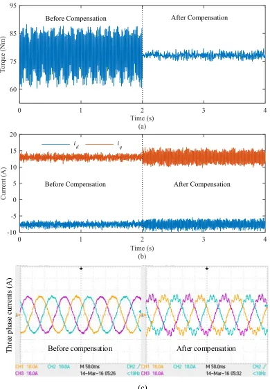
Figure 3-5. The waveforms obtained before and after applying the GA based current compensation when the IPM machine was under the rated torque condition. (a) The output torque. (b) The dq-axis currents. (c) Three-phase currents. ... 47
Figure 3-6. The waveforms obtained before and after applying the GA based current compensation when the IPM machine was under a load torque of 45 Nm. (a) Measured shaft torque. (b) Measured stator currents in dq-axis. ... 48
Figure 3-7. The calculated optimal dq-axis stator currents in Sim1. ... 54
Figure 3-8. The ouput torque before and after minimization in Sim1. ... 54
Figure 3-9. The calculated optimal dq-axis stator currents in Sim2. ... 54
Figure 3-10. Torque before and after torque ripple minimization in Sim2. ... 55
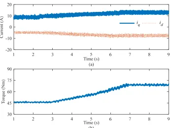
Figure 3-11. The measured dq-axis currents before and after torque ripple minimization in Test 1. (a) At load torque of 45 Nm. (b) At load torque of 70 Nm. ... 56
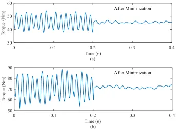
Figure 3-12. The measured shaft torque before and after minimization using the proposed approach in Test 1. (a) At 45 Nm. (b) At 70 Nm. ... 56
xvi
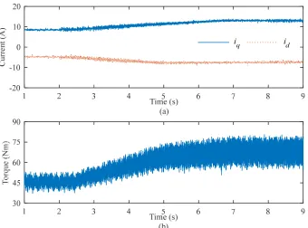
Figure 3-14. The dq-axis currents and the measured shaft torque before applying torque ripple minimization in Test 2. (a) Stator currents. (b) Measured shaft torque. ... 58
Figure 3-15. The dq-axis currents and the measured shaft torque employing the proposed torque ripple minimization in Test 2. (a) Stator currents. (b) Measured shaft torque. ... 59
Figure 4-1. Inductance estimation diagram. (a) Control. (b) Implementation. ... 63
Figure 4-2. Estimated dq-axis inductances at 100 RPM and 400 RPM under varying loading conditions. ... 64
Figure 4-3. The variation of dq-axis inductances of the test machine with respect to the stator current under MTPA control. ... 65
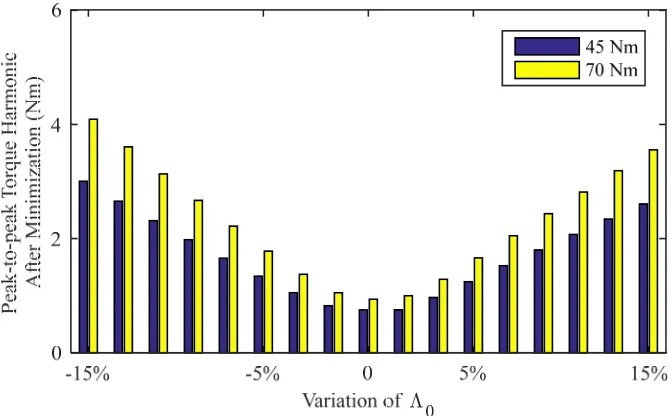
Figure 4-4. The influence of magnet flux DC component variation on torque ripple minimization when the load torque is 45 Nm and 70 Nm. ... 69
Figure 4-5. The influence of magnet flux harmonic component variation on torque ripple minimization when the load torque is 45 Nm and 70 Nm. ... 69
Figure 4-6. Influence of inductance variation on torque ripple minimization when the load torque is 45 Nm and 70 Nm, respectively. ... 70
Figure 4-7. Torque ripple minimization errors under variations of magnet flux and the inductance. (a) At load torque of 45 Nm. (b) At load torque of 70 Nm. ... 71
Figure 4-8. Control diagram of the test machine with torque ripple minimization. ... 72
Figure 4-9. Torque ripple of the test machine due to magnet flux variation at 45 Nm. ... 73
Figure 4-10. Torque ripple of the test machine due to magnet flux variation at 70 Nm. . 73
Figure 4-11. Measured shaft torque before and after torque ripple minimization with accurate and inaccurate inductance at 45 Nm. ... 74
Figure 4-12. Measured shaft torque before and after torque ripple minimization with accurate and inaccurate inductance at 70 Nm. ... 75
Figure 5-1. Torque harmonic magnitude vs. the speed harmonic magnitude. ... 78
Figure 5-2. The relationship between the 12th harmonic current, iq12, and the magnitude of
the 12th torque harmonic, Th12. ... 80
Figure 5-3. The diagram of the proposed hierarchal fuzzy logic controller (FLC). ... 81
Figure 5-4. The membership functions. (a) The membership function of m12. (b) The
xvii
Figure 5-5. The shaft torque measured at no-load condition. (a) Torque waveform. (b) Harmonic components. ... 86
Figure 5-6. The implementation diagram of the proposed fuzzy logic controller. (a) Machine control. (b) Speed harmonic detection. ... 87
Figure 5-7. The FLC inputs and outputs in Ex1 without using rule 15. (a) Input variable m12. (b) Input variable Δm12. (c) Output Iq12. (d) Output ϕiq12. ... 89
Figure 5-8. The dq-axis currents in Ex1 without using rule 15. ... 89
Figure 5-9. The measured torque in Ex1 without using rule 15. (a) Torque waveform. (b) The 12th torque harmonic magnitude. ... 90
Figure 5-10. The measured speed in Ex1 without using rule 15. (a) Speed waveform. (b) The 12th speed harmonic magnitude. ... 90
Figure 5-11. The FLC inputs and outputs in Ex1 using rule 15. (a) Input variable m12. (b)
Input variable Δm12. (c) Output Iq12. (d) Output ϕiq12. ... 91
Figure 5-12. The dq-axis currents in Ex1 using rule 15. ... 91
Figure 5-13. The measured torque in Ex1 after using rule 15. (a) Torque waveform. (b) The 12th torque harmonic magnitude. ... 92
Figure 5-14. Measured speed in Ex1 after using rule 15. (a) Speed waveform. (b) The 12th speed harmonic. ... 92
Figure 5-15. The magnitude of the 12th torque and speed harmonics at different control
gains in Ex2. (a) Torque Harmonic. (b) Speed Harmonic. ... 93
Figure 5-16. The torque in Ex3 obtained from torque sensor with a load torque of 70 Nm. (a) Torque waveform. (b) The 12th torque harmonic magnitude. ... 94
Figure 5-17. The rotor mechanical speed in Ex3 obtained from the encoder. (a) Speed waveform. (b) The 12th speed harmonic magnitude. ... 94
Figure 5-18. The measured shaft torque in Ex3 at 20 Nm. (a) Torque waveform. (b) The 12th torque harmonic magnitude. ... 95
xviii
NOMENCLATURE
A list of principle symbols is given here; there are more symbols used in this thesis, which have been defined locally. For simplicity, magnet flux is used to denote magnet flux linkage with respect to a specific machine in this thesis.
ttotal total torque produced by an electric machine ttotal,τ total torque produced at temperature τ
T0 DC component of the total torque
th harmonic component of the total torque Thk magnitude of the kth torque harmonic te electromagnetic torque
tcog cogging torque
Tck magnitude of the kth cogging torque harmonic
tL load torque
TL0 DC component of the load torque
sa, sb, sc total flux in abc-axis
λa,λb, λc magnet flux in abc-axis
Λabc,k magnitudeofthe kth magnet flux harmonic in abc-axis
λd, λq magnet flux in dq-axis
λdh, λqh harmonic components of the dq-axis magnet flux dk, qk magnitudes of the dq-axis kth magnet flux harmonics
Λdk,τ, Λqk,τ magnitudes of the dq-axis kth magnet flux harmonics at temperature τ 0 DC component of the magnet flux
Λ0,τ DC component of the magnet flux at temperature τ ua, ub, uc abc phase voltages
Uabc,k magnitude of the kth voltage harmonic in abc-axis ud, uq, dq-axis voltages
udk, uqk kth voltage harmonics in dq-axis
xix
Ud0, Uq0 DC components of the dq-axis voltages
ia, ib, ic abc phase currents id, iq dq-axis currents
Id0, Iq0 DC components of the dq-axis currents
idh, iqh dq-axis current harmonics
Idk, Iqk magnitudes of the dq-axis kth current harmonics
Idk*, Iqk* magnitudes of the dq-axis kth harmonic current references Laa, Lbb, Lcc abc phase self-inductances
Ld, Lq dq-axis inductances
Mab, Mbc, Mca mutual inductances between corresponding phases Lls leakage inductance
LA saliency-independent inductance LB saliency-dependent inductance
ω electrical rotor speed Ω0 average electrical speed
ωm mechanical rotor speed m0 average mechanical speed
mk magnitude of the kth mechanical speed harmonic
θ electrical rotor position NP number of machine pole pairs
ϕλk phase angle of the dq-axis kth magnet flux harmonics
ϕidk, ϕiqk phase angle of the dq-axis kth current harmonics
ϕidk*, ϕiqk* phase angles of the dq-axis harmonic current references
ϕck phase angle of the kth harmonic of cogging torque k phase angle of the kth speed harmonic
tk phase angle of the kth torque harmonic J combined moment of inertia
xx
R winding resistance
R0 winding resistance at temperature Temp0
Temp stator winding temperature
τ magnet temperature
αcu copper thermal resistive coefficient
α0, αqk, αqk magnet flux thermal coefficients g1, g2, g3 objective functions
1, 2, 3 weights of the objective functions
Kϕ, Ki control gains of the fuzzy logic controller
Δt sampling time period
1
CHAPTER 1
INTRODUCTIONS
1.1 Overview and Motivations
The electric vehicle (EV) has been receiving increasing research and development interest in recent years due to the environmental issues caused by the internal combustion engine (ICE) vehicle [1]-[12]. Environment and Climate Change Canada reported that the transportation sector contributes 23% greenhouse gas (GHG) emissions in 2014, and this number is estimated to be increasing. Among all the provinces, Ontario contributed 23% of the national total GHG emission. As indicated in the 2016 Greenhouse Gas Progress Report by the Environmental Commissioner of Ontario, among all economic sectors, the transportation sector has become the biggest contributor in producing GHG in Ontario. The report also claims that transportation is the fastest growing share of GHG emissions and it is a big challenge to reduce the carbon footprint by 9% by the year 2020. To achieve this target, a Cap and Trade Program that puts a price on GHG pollution will be active from January 1, 2017 [12]. Similarly, in the United States, the Clean Air Act is designed to control the air pollution caused by different sources on a national level. The Zero Emission Vehicle Program is developed under the California Air Resource Board (CARB) to reduce emissions from mobile sources. It is reported that the mobile sources account for over half of the total emission, which contribute to near 40% of GHG. On the other hand, oil is the energy source of ICE vehicles, but oil has limited reserves, which will eventually deplete. In this way, the government is encouraging both vehicle manufacturers and consumers to shift towards EVs. This is in order to reduce fossil fuel usage and GHG emissions. With such a long-term environment-friendly commitment and policies from the government, the EV market has been growing fast recently, and it is predicted that the EV share will reach at least 50% of the global light-duty vehicle sales by 2050 [1].
2
(IMs) and permanent magnet (PM) machines [8]-[11]. The switched reluctance (SR) machine is a promising candidate that can be used for traction as well [8], [14], [15]. Comparative performance studies of these four kinds of electric machines are conducted in [9] and [10] in the context of EVs. Table 1-1 lists the comparative results in terms of power density, efficiency, controllability, reliability, technological maturity and cost. These are important factors in electric machine selection for EV application [9]. It is clear that the PM machine is superior in terms of its power density and efficiency. These two features make the PM machine the most favorable for the EV traction application. For instance, EVs such as the Ford Focus, Nissan Leaf, Mitsubishi i-MiEV, BYD e6 and Smart ED use PM motors for propulsion. Table 1-1 also shows that the PM machine has disadvantages in terms of cost, controllability, technological maturity and reliability compared to its counterpart, the IM. In fact, there are many open research topics to improve PM machine technology for EV applications.
TABLE 1-1:ELECTRIC PROPULSION SYSTEM EVALUATION [9]
Propulsion systems Characteristics
DC Motor Induction
Motor PM Motor SR Motor Power Density
Efficiency Controllability
Reliability Technological Maturity
Cost
2.5 2.5 5 3 5 4
3.5 3.5 5 5 5 5
5 5 4 4 4 3
3.5 3.5 3 5 4 4
∑ Total 22 27 25 23
Fi un P in m ap ca [1 fa g fo H m as T ap ro m ra pr si
igure 1-1. Inst nder sinusoidal
ermanent m ncludes surf mounted type
pplications, ases such as 19]-[22]. Th acilitate inte eneral, torqu ocuses on to However, the mounted PM s a special ca The IPM ma
pplications. otor and stat machine is fi ated current resented in F inusoidal cur
antaneous torq l current excita
magnet mach face-mounted
e and the in and their s s in-wheel m here are als egrated char
ue ripple is orque ripple e proposed th
(SPM) mac ase of the IP achine used
The details tor of the IPM
rst analyzed t condition Figure 1-5. rrent excitat
que waveforms ation at differen
ines are gen d, surface-in nterior type tructures are motors, the o
so line-start rging by ut a common e modeling a
heoretical an chines as we PM machine, for this inve
of the finite M machine a d in the FEA
is demonst It can be se ion.
3 s obtained from
nt rotor positio
nerally divid nset, interior PM machi e demonstra outer rotor st PM machin tilizing the n issue for a
and minimiz nd practical a ell. This is b
, in terms of estigation is
e element an are presente A environmen
trated in Fi een that the t
m the electrom ons [13].
ded based on r and line-st ines are wid ated in Figu tructure is e
nes for the machine st all PM mac zation for in approaches because the S
f mathematic s a downsca
nalysis (FEA ed in Figure
nt. The torq igure 1-4. T torque rippl
magnetic mode
n their rotor tart types [1 dely adopted ure 1-2 [7]. employed in EV tractio tator windin chines. Ther
nterior PM are applicab SPM machin cal modeling aled design p
A) model an 1-3. Perform que waveform
The excitat e is quite la
l of a SPM m
r structure, w 18]. The sur
d in EV tra In some sp the PM ma on applicatio ngs [6], [23 refore, this t (IPM) mach ble to the sur ne can be vi g and control prototype fo nd the devel mance of the m obtained a tion currents arge even un
achine which rface-action pecial chine on to 3]. In thesis hines. rface-iewed
l. or EV
Fi
Fi
igure 1-2. Ove
igure 1-3. Desi
rall PM machin
ign of the IPM
(a) ne architecture
machine. (a) 2
4 es [7]. (a) SPM
(a)
(b) 2D FEA model
(b) M machine. (b)
l. (b) Rotor and
IPM machine.
5
Figure 1-4. Torque waveform under 11 A rms/phase current excitation at 100 RPM.
Figure 1-5. Three-phase stator currents of 11 A rms/phase used in the FEA.
Here, the torque ripple is quantified as:
max min
100% average
torque torque torque
.
It has been found from the FEA that the torque ripple produced by the IPM machine at the rated current condition is 44%, as shown in Figure 1-4. The experimental validations, which will be detailed later, are in good agreement with the FEA results. Therefore, considerable research efforts are required to tackle the torque ripple issue to improve the overall performance of this IPM machine for EV applications.
This thesis is dedicated to minimize the torque ripple in PM machines. In order to achieve precise torque control, an accurate measure of torque during operation is required. But a direct measurement of torque is generally unavailable in the PM machine drive system,
To
rq
ue
(
N
m
)
Current
6
due to the cost concerns of using torque transducers. In fact, the torque transducer also has limited accuracy in torque measurement due to the limitations in bandwidth and sampling rate. Therefore, torque ripple modeling and estimation has been extensively investigated in the literature to achieve accurate PM machine torque control with minimum ripple. However, due to the machine and drive nonlinearities, none of the existing torque ripple modeling and minimization methods are claimed to be universally effective. So the candidate in this thesis is motivated to tackle the challenges in PM machine torque ripple minimization through novel control and optimization techniques based on comprehensive modeling, estimation and measurement of torque ripples.
1.2 Literature Review
Apart from the EV application, PM machine can be used in many other applications as well, such as robotics and aerospace [24]-[30]. In most of the applications, smoothness in the output torque is critical and the torque ripple is generally undesirable. This is because the torque ripple can produce mechanical vibration and acoustic noise, and degrade the overall machine performance. Therefore, a large amount of research work has been proposed to minimize the torque ripple for PM machines.
7
Recent research investigations on torque ripple minimization can still fall under the two categories of machine design technique and active control technique. These techniques are summarized and presented in the following two sub-sections.
1.2.1 Machine Design Techniques for Torque Ripple Reduction
In terms of PM machine design, given the required machine performance, such as speed, power density, efficiency and constant power range, the basic design parameters of the machine are determined. The design parameters include the number of phases, slots and poles, the machine dimensions, and the steel and magnet materials. The control factors left to achieve torque ripple minimization are limited. The recent research is focused on fine tuning the magnetic pole design, or the stator teeth and winding design for reducing the cogging torque and spatial harmonics in the flux and the inductances. But in some investigations, both the stator and rotor are optimized to achieve better torque ripple minimization performance.
The most common technique is controlling the machine pole design. A magnet step-skewing technique is proposed in [32] to minimize the cogging torque of a PM machine. A genetic algorithm (GA) is employed to optimize the skew angle to achieve minimum cogging torque. Torque ripple and cogging torque variation in a PM machine with a skewed rotor has been investigated in [33]. It is shown that the skewing with steps does not necessarily reduce torque ripple but may cause it to increase.
8
proposed magnet pole design. Magnet segmentation is also considered in the design to reduce the manufacturing complexity. Different magnet shapes in the radial direction are explored in [36] for torque ripple minimization. The magnet pole is divided into a number of layers at first, and then it is modeled analytically as a function of the magnet height and opening angle. The resulting design shows satisfactory performance on torque ripple minimization, but the magnet shape is quite complicated and the average torque is decreased as well. A computationally efficient finite element method is proposed in [37] to calculate the cogging torque of the PM machine with different magnet shapes in the radial direction. Thanks to the ease of computation by using the proposed approach, a GA is employed in the study to optimize the magnet shape in the radial direction for cogging torque minimization.
An analytical model is proposed in [38] to calculate the cogging torque of a segmented pole PM machine. Then, a particle swarm optimization technique is applied to find the optimal widths and displacement of the magnet segments for torque ripple minimization. In [39], a magnet segmentation concept is adopted, but this investigation focuses on the machine pole design with hybrid magnets for torque ripple minimization as well as cost reduction. A hybrid magnet design with the NdFeB in the center and ferrite magnets on both sides is proposed to make the flux density approach a sinusoidal distribution. Skewing is also employed in the machine design to achieve near ideal flux distribution. This rotor design technique with hybrid magnets is also investigated in [40] using an analytical model that can predict the magnetic field, back electromotive force (back-EMF) and electromagnetic torque. To further reduce the torque ripple, variables of the middle magnet arc to pole-pitch ratio, side magnet arc to pole-pitch ratio, and side to middle magnet remanence ratio are investigated as well.
9
it reduces the torque ripple and increases the average torque at the same time. It is also concluded that this approach is less complex in terms of manufacturing.
However, it is found in [43] that the machine loading condition has great influence on the cogging torque and back-EMF waveforms. Therefore, the effectiveness of different rotor design techniques for torque ripple minimization should be evaluated under loading conditions as well. Specifically, PM machines with rotor skewing are examined in this investigation, and it is reported that the machines should be skewed by one actual cogging torque period to effectively eliminate the torque ripple.
Research work has also been done to reduce torque ripple by modifying the stator design. The main objective is to make the magneto motive force (MMF) produced by the stator current excitation near sinusoidal. To this end, some of the rotor design techniques may also be employed together with the proposed stator design for a combined torque ripple minimization. In distributed winding machines, making a near sinusoidal MMF distribution is usually easier, but in concentrated winding machines, much more effort is required. Torque ripple induced by the asymmetric local saturation as well as cogging torque in tooth-coil winding (TCW) PM machines have been investigated in [44]. The authors propose a machine geometry optimization technique by using unequal stator teeth width to eliminate the 6th torque harmonic. Magnet skewing is employed in the rotor design to reduce the higher torque harmonic orders. The adjacent stator teeth widths are optimized in [45] to further improve this stator design technique for the TCW PM machine. It is recommended as a feasible approach in design for other machine types to address the magnetic asymmetries introduced by local saturation. The authors concluded that the proposed unequal stator teeth width method is only optimized for a specific loading condition. Therefore, the most frequent operating condition should be considered during the design.
10
To suppress torque ripple by modifying the machine design could cause significant manufacturing difficulties because the machine structure is usually more complicated by using techniques such as skewing and different magnet shapes. Moreover, the manufacturing tolerance should never be ignored. In [47] and [48], the manufacturing variations and tolerances are taken into account to make the PM machine design more robust in terms of torque ripple minimization. As indicated in both studies, the manufacturing tolerance and assembly process variation could have significant effects on torque ripple as well. So, defining proper tolerances for the manufacturing processes are necessary to ensure a low torque ripple in PM machines.
1.2.2 Machine Control Techniques for Torque Ripple Reduction
Although many design approaches are proposed for torque ripple minimization, control strategies are preferred in recent years. This is because the machine design based approach is limited in terms of cost and manufacturing complexity, while the machine control based approach can be implemented in most electric machine drive systems without much effort. In addition to this, for some applications, the requirement for torque ripple is different under a range of operating conditions, and thus torque ripple minimization for such cases can only be achieved through control strategies [31].
Extensive research has been conducted to model and minimize the torque ripple of PM machines [49]-[60]. The key to these studies is to determine an optimal stator current including appropriate harmonic components to reduce the torque ripples. The machine control approaches can be further divided into two categories, the feed-forward compensation and the feedback control techniques.
11
In [50], optimal currents are designed to minimize the torque ripple of a SPM machine based on the normalized EMF coefficients and cogging torque obtained through offline tests. Minimization of both the rms current and torque ripple is considered by using the Lagrange multiplier to optimally design the stator currents. The torque model is first expressed under multiple reference frames (MRF) in [51] with consideration of the flux harmonics and cogging torque. With MRF, the harmonic current magnitude can be controlled by using PI controllers to achieve low torque ripple by following the optimal current command obtained from the Lagrange optimization technique. An adaptive notch filter is also explored to estimate the fundamental current frequency and extracting the current harmonic components with reduced computational time. Geometrical representation of the optimal current vectors is proposed in [52]. In such a way, the optimal currents can be obtained through geometry relations instead of the Lagrange optimization. In addition, an artificial neural network (ANN) approach is employed to improve the torque ripple minimization performance. The demagnetization effect of a PM machine during torque ripple minimization is considered in [53]. In this study, the magnet flux magnitude is estimated online through an extended Kalman filter, such that the torque ripple model can be updated under different operating conditions. The compensation currents are then calculated with higher accuracy for more effective torque ripple reduction.
As demonstrated in these existing torque ripple minimization studies, the stator currents are optimally designed based on the estimated torque ripple. But this only produces reference stator currents for torque ripple minimization. Tracking these reference currents precisely is also important for torque ripple minimization. The repetitive current control strategy is proposed in [54] to improve the q-axis current control, which has been modified to suppress torque ripple.
12
torque ripple minimization during steady state operation of the test machine. However, torque transducers are usually too expensive to be used in regular PM machine drives. Thus, the torque ripple of a PM machine is more feasibly obtained by using a torque estimator/observer.
In [57], an analytical model for calculating the instantaneous torque is proposed in an effort to design the excitation currents for torque ripple minimization. The torque calculated by using the proposed model is in good agreement with the FEA result. So the proposed torque ripple model can be employed to estimate the instantaneous torque as the feedback control signal for precise torque ripple suppression. However, the authors propose to simplify the proposed model by ignoring the reluctance torque to design the feed-forward compensation currents for torque ripple minimization. This is because the comprehensive model contains derivative terms, which could bring instability into the drive system. The torque feedback control based on the comprehensive model is recommended to work in combination with the feed-forward compensation for fine-tuning the stator currents to achieve better performance in torque ripple minimization. In [58] and [59], the use of a piezoeletric polymer sensor is explored for torque ripple measurement. This kind of sensor can be installed on the motor base to measure the torque ripple induced vibration. The measured vibration signal can be used for torque feedback control. The speed sensor information is also explored for torque ripple minimization. Some research focuses on using speed errors for torque ripple minimization, because speed ripples are induced by torque ripples [60], [61].
The torque ripple caused by unbalanced winding resistance is also investigated in [62]. Although the torque ripple is from a different source, it also relies on stator current control. Unbalanced stator winding resistances cause unbalanced phase currents and result in high torque ripple. It is proposed that the stator resistance can be estimated online to address the unbalance effect for torque ripple minimization.
13
torque ripple reduction [63]-[71]. For example, a new DTC method is proposed in [63] to reduce the torque and flux ripples through a voltage vector with an optimal phase angle. In [65], the authors explore the option of using a matrix converter for the DTC strategy with duty cycle optimization for PM machine drive systems. A torque ripple reduction of 30% is reported. However, these methods are more about improving the DTC control strategy itself. They are different from the work that has been done in this thesis.
There are many other factors that should be compensated during torque ripple minimization. For example, the torque model is extended to include position offsets in [16]. The authors study the torque ripple due to position offset and compensate this effect based on a polynomial approximation technique. In addition, the current sensor error should also be considered during torque ripple minimization.
From the above review, a considerable amount of research has been done for torque ripple modeling and minimization in the literature. But in these existing studies, the torque ripple model does not consider the harmonic currents induced by the inverter non-linearity [72]-[78]. Moreover, the torque ripple models mostly rely on machine parameters, which vary widely during machine operation. For example, temperature increase in the machine during operation can cause the magnet flux to reduce from its nominal value [79]-[84]. Also, different loading conditions bring different levels of magnetic saturation in the machine, which will cause the inductance to change [11], [85]-[92]. During torque ripple minimization, existing methods mostly consider only optimizing the magnitude of the stator currents. So far, the harmonic current phase angle has not been considered in the optimization. In this investigation, it is shown that, by considering the harmonic current phase angle in the optimization, the magnitude of the harmonic current required for minimizing the torque ripple can be reduced significantly.
1.3 Research Objective
The smoothness of the PM machine’s output torque is an important performance index, which is required in many applications, such as in direct-drive EVs. Therefore, this thesis aims to address the torque ripple problem for PM machines. This overall objective is divided into the following sub-objectives.
14
produced by a PM machine through theoretical study, numerical simulations, FEA and experimental tests.
2) Model the torque ripple comprehensively by including multiple sources that can cause torque ripple during PM machine operation.
3) Validate the proposed torque ripple model through experimental tests under various conditions. This is to understand the sensitivities of the proposed model during the entire operating range, such as machine parameter variations.
4) Propose torque ripple minimization solutions based on the proposed model and implement them in PM machine control.
5) Analyze the performance of the proposed torque ripple minimization approaches through simulation and experimental investigation.
6) Explore novel model-free torque ripple minimization methods that can be extended to other PM machines.
1.4 Research Contributions
This thesis proposes novel and advanced torque ripple modeling and minimization techniques. Major contributions are listed as follows:
1) A comprehensive torque ripple model for PM machines is proposed by including the torque ripple resulting from the cogging torque, spatial harmonics in the permanent magnet flux and the time harmonics in the stator current induced by the non-linearity of the machine and the drive. It is found that the interaction of magnet flux harmonics and current harmonics can generate torque ripple as well as a small average torque component.
2) A novel genetic algorithm (GA) based torque ripple minimization approach is proposed, which determines the optimum harmonic currents to achieve minimum torque ripple. The proposed GA based optimization includes two other objectives of minimizing the harmonic current magnitude and maximizing the average torque component produced by the injected harmonic currents.
15
extensive experimental investigations. Then, by estimating only the magnet flux DC component online, both the DC and harmonic magnet flux components are updated in the torque ripple model. With such a torque ripple model, a novel adaptive current optimization approach is proposed to adaptively update the stator currents with respect to the variation of magnet temperature.
4) A novel torque ripple model considering magnetic saturation is proposed, in which the inductance term is replaced by an inductance model formulated using the measurable electrical quantities. In this way, the proposed torque ripple model does not include the inductance term, and thus it is not influenced by the magnetic saturation. With such a model, the stator harmonic currents can be adaptively designed under different loading conditions to produce smooth torque.
5) An analytical solution of optimal stator current for torque ripple minimization is derived from the proposed torque ripple model, in which the magnetic saturation is considered as well. The optimal stator current is computed from the proposed analytical expression, so it is computationally efficient and does not involve iterative computation. Therefore, the proposed approach is able to minimize the torque ripple when the machine is operating under both transient state and steady state. Magnetic saturation is considered by modeling the inductance with respect to the stator current under maximum torque per ampere (MTPA) control, which is derived from extensive experimental investigations.
6) Investigations on how the machine parameter variations influence the performance of optimal stator current design for PM machine torque ripple minimization are also conducted. Influences from the variations of the magnet flux inductances are quantified and inaccurate cogging torque measurement is also considered. The results show that the influence of parameter variations on torque ripple is significant, especially when both the magnet flux and inductances are varying. Thus, machine parameter variation should be considered in the optimal stator current design in order to improve the performance of torque ripple minimization.
16
found that the magnitude of the speed harmonic is proportional to the magnitude of the torque harmonic of the same order. Therefore, the speed harmonic can be used as the feedback control signal to minimize the torque harmonic of the same order. Then, a novel fuzzy logic based controller is proposed to minimize the torque harmonic by using the measured speed harmonic as the feedback control signal.
1.5 Dissertation Layout
Chapter 2 presents the comprehensive torque ripple modeling derived from the magnetic co-energy machine model. The sources of torque ripple are investigated and demonstrated through a laboratory IPM machine. In addition, machine parameters that could vary during machine operation are also investigated and the proposed torque ripple model is improved by incorporating the magnet flux variation due to temperature change and inductance variation due to magnetic saturation.
Chapter 3 proposes the feed-forward based torque ripple minimization techniques. The genetic algorithm is proposed at first to optimally design the stator harmonic currents including the harmonic current magnitude and the phase angle to minimize the torque ripple estimated from the proposed torque ripple model. Then, a computationally efficient analytical solution is proposed to calculate the optimal stator harmonic current.
Chapter 4 discusses the influence of machine parameter variation on PM machine torque ripple minimization. The relation between the parameter variation and torque ripple minimization is mathematically modeled. Then, numerical and experimental studies are conducted on an IPM machine, which demonstrate that the accuracy of the machine parameter influences the torque ripple minimization performance significantly.
Chapter 5 proposes a fuzzy logic based closed-loop torque ripple minimization method by using the speed harmonic magnitude as a measure of the torque harmonic magnitude. With the feedback control signal, the torque ripple can be minimized without requiring an accurate torque ripple model and machine parameters.
17
CHAPTER 2
COMPREHENSIVE TORQUE RIPPLE MODELING
2.1 Introduction
Torque ripple is a part of the total torque produced by a permanent magnet (PM) machine, which consists of the PM torque, the reluctance torque and the cogging torque. In this study, an analytical torque ripple model for the PM machine is proposed based on the magnetic co-energy model. The proposed model includes the torque ripple resulting from the magnet flux harmonics, the current harmonics, as well as the cogging torque. During the study, it is found that the interaction of magnet flux harmonic and current harmonic can generate torque ripple as well as a small average torque component. In addition, because the torque ripple model is highly dependent on the machine parameters, the variation of the machine parameters has been considered for a comprehensive torque ripple modeling.
18
produces smooth output torque during operation, which has been verified before conducting the proposed test here. Thus, the torque produced by a PM machine is not just the DC component as calculated by the simple torque equation as in [18] and [93].
TABLE 2-1.THE PARAMETERS OF THE IPMMACHINE OBTAINED FROM FEA
Rated Current 15 A Winding Resistance 1 Ω Rated Speed 575 RPM Magnet Flux 0.67 Wb Maximum Speed 5,100 RPM d-axis Inductance 30.4 mH Rated Voltage 275 V q-axis Inductance 87.5 mH Rated Torque 70 Nm Leakage Inductance 5.5 mH
Rated Power 4.25 kW Number of Pole Pairs 4 Stator Bore Diameter 135 mm Number of Slots 48
Air-Gap Length 0.5 mm Number of Turns per Phase 224
Stack Length 136 mm Magnet NdFeB35
Fi
Fi
2.
T th m
igure 2-2. The
igure 2-3. Torq
.2 Generaliz
The total torq he current d machine stato
measured thre
que measureme
zed Torque R
que produce dependent co
or current.
ee-phase curren
ent setup for te
Ripple Mode
d by a PM m omponent an
19 nts of the IPM m
esting the propo
eling
machine can nd the cogg
total e c
t t t
machine at 100
osed torque rip
n be denoted ging torque,
cog
0 RPM.
pple minimizat
d as in (2.1) which does
tion approach.
, a summati s not rely o
on of n the
20
where ttotal is the total torque produced by a PM machine, te is the torque produced by the
interaction of the stator currents and air-gap flux, and tcog is the cogging torque.
According to the magnetic co-energy model, te can be calculated as (2.2) [57], [94].
1 2
T s T abc
e P abc abc abc
dL d
t N i i i
d d
(2.2)
where iabc=[ia ib ic]T is the three phase stator current vector, Ls is the inductance matrix,
which has been defined in Appendix A, λabc=[λa λb λc]T is the magnet flux linkage vector,
θ is the electrical rotor position, and NP is the number of PM machine pole pairs.
Applying the dq-axis transformation to (2.2), which has been presented in Appendix B, the torque equation (2.3) is obtained.
T T dqe p dq dq dq dq dq
d
t K L i i i
d
(2.3)
where Kp=3NP/2, Ldq=diag{Ld, Lq} is the dq-axis inductance matrix, λdq=[λd λq]T and idq=[idiq]T are the dq-axis flux linkage vector and current vector, and ‘’ is cross product
defined as:
Ta b c d ad bc. (2.4)
Then, a generalized torque model for the PM machine is derived by substituting (2.3) into (2.1).
T T dqtotal P dq dq dq dq dq cog
d
t K L i i i t
d
(2.5)
Both the magnet flux linkage and stator currents contain harmonics, so λdq and idq are
expressed as the summations of their DC and harmonic components as in (2.6).
0 , 0
dq dq dqh idq Idq idqh
(2.6)
where dq0 and λdqh are the dq-axis magnet flux DC and harmonic components; Idq0 and
idqh are the dq-axis current DC and harmonic components, respectively. The subscript ‘0’
and ‘h’ indicate the DC and the harmonic components, respectively, which holds
throughout this thesis. The lower case letters represent the variables that are a function of time or rotor position, and the uppercase letters represent the magnitudes of a variable or a constant, which holds throughout this thesis as well.
21
0 0
0
0
λ
Λ λ T T dqh
total p dq dq dq dqh dq dqh dq dqh dq dqh cog
d
t K L I L i I i I i t
d
(2.7)
From (2.7), the torque ripples are mainly caused by magnet flux harmonics, current harmonics and the cogging torque, if the spatial harmonics of the inductances are ignored. To categorize different torque components, (2.7) can be rewritten as (2.8), where different torque components are detailed as in (2.9), including the first torque component, Te0, produced by the interaction of the dq-axis magnet flux and current DC components;
the second torque component, te1, is a summation of the harmonic torques produced by
the interaction of the dq-axis magnet flux DC component and harmonic currents and the interaction of harmonic flux and DC current component; and the third torque component, te2, produced by the interaction of harmonic flux and harmonic currents.
0 1 2
total p e e e cog
t K T t t t (2.8)
0 0 0 0
1 0 0 0 0
2
( )
( ) ( )
( )
T
e dq dq dq dq
dqh
T T T
e dq dq dq dqh dq dqh dqh dq dq
dqh
T T
e dq dqh dqh dqh dqh
T L I I
d
t L I i L i I I
d d
t L i i i
d (2.9)
The DC components of the magnet flux and currents in the dq rotating reference frame can be represented as:
0 0
0 0 0
0 T
dq
T
dq d q
I I I
(2.10)
where 0 is the d-axis average magnet flux, and Id0 and Iq0 are the DC components of dq
-axis currents. According to [4], the magnet flux linkage harmonics can be denoted as:
cos sin dk k dh k dqhqh qk k
k k k
(2.11)where dk and qk are the magnitudes of the dq-axis kth flux harmonic components, and
ϕλk is their phase angle. Here, k can take values from 6, 12, 18, 24, …. Similarly, the dq