ABSTRACT
Aly, KARIM ALY ABDELMOATY ELSAYED. Embedded Aligned Carbon Nanotube Sheets for Strain and Damage Sensing in Composite Structures. (Under the direction of Philip David Bradford).
The world demand for fiber reinforced composite materials has been steadily increasing because of the widespread adoption of this class of material in many markets. The automotive, aerospace, marine and energy sectors account for a large percentage of this grow. Outstanding fatigue performance, high specific stiffness and strength, and low density are among the most important properties that fiber reinforced polymer composites offer. Furthermore, their properties can be tailored to meet the specific needs of the final applications. However, this class of material is composed of multiple layers of inhomogeneous and anisotropic constituents, i.e. fibers and matrix. Therefore, this laminated nature make the composite material prone to intrinsic damage including interfacial debonding and delamination and their strength and failure are dependent on the fiber architecture and direction of the applied stresses.
In this dissertation, the usage of CNTs for performing strain and damage sensing in composites is evaluated. This was enabled by embedding aligned sheets of two millimeters long, interconnected CNTs into laminated structures that were then subjected to different forms of mechanical loading. The localization of the CNT sheets inside the host structure was done using a novel technique that allowed for carrying out the embedment task conveniently and repeatedly. The real-time electrical resistance change of the CNT sheets in response to the applied mechanical stresses was measured in-situ so that the electromechnical behavior of the CNTs could be linked to the strain change and damage in the host structure. The quasi-static and dynamic flexural, axial tensile and compression loadings of the composite structures revealed that the CNT sheets exhibited sensitivity, stability and repeatability which are vital properties for any successful health monitoring technique.
Furthermore, the CNT piezoresistive behavior was linear in tension and non-linear in compression and can be characterized as anti-symmetric around zero strain all the way until fracture. The sensitivity of the CNT sheets to tensile and compression loadings could be easily tuned by applying post treatment techniques, like plasma treatment and pre-straining and the optimization of the number of the CNT sheets prior to the embedment. Additionally, the CNTs showed increasing continuous linear piezoresistive behavior in response to the growing interlaminar shear with few normalized electrical resistance change spikes corresponding to delaminations inside the laminated structure.
Embedded Aligned Carbon Nanotube Sheets for Strain and Damage sensing in Composite Structures
by
Karim Aly Abdelomoaty Elsayed Aly
A dissertation submitted to the Graduate Faculty of North Carolina State University
in partial fulfillment of the requirements for the degree of
Doctor of Philosophy
Fiber and Polymer Science
Raleigh, North Carolina 2016
APPROVED BY:
_______________________________ _______________________________ Philip D. Bradford Tushar Ghosh
Committee Chair
DEDICATION
BIOGRAPHY
ACKNOWLEDGMENTS
I would like to express my deepest gratitude to my supervisor Dr. Philip Bradford for giving me the opportunity to be one of his grad students and to join his team. He has always been willing to help and to give his best suggestions and invaluable comments. Dr. Bradford has always been supportive to me not only on the academic, but also on the personal level. I would have never been able to start or to finish my dissertation without your guidance, patience and support. I could not have imagined having a better advisor and mentor for my Ph.D. study. I will always be indebted to you. Thank you.
I would like also to offer my sincerest gratitude to my committee members, Dr. Tushar Ghosh, Dr. Russell Gorga and Dr. Kara Peters for the encouragement and support. I really appreciate the effort you have put in reading my work and in offering me the opportunity to learn from your experiences through your constructive discussion and thoughtful criticism.
I need to further thank all my friends and colleagues in Braford’s group, particularly my fellow lab mate Ang Li, who always took the time to help me with the experiments. I want to thank him for his support, help and interest. Silver, Mohamed Nafadi, Mohamed Gamal and Al-Sayed Mashaheet, your help is highly appreciated.
TABLE OF CONTENTS
LIST OF TABLES ... x
LIST OF FIGURES ... xi
1 Introduction ... 1
2 Literature Review ... 4
2.1 Carbon Nanotubes ... 4
2.1.1 Carbon Nanotube Properties ... 4
2.1.2 Carbon Nanotube Growth ... 6
2.2 Vertically Aligned Spinnable Carbon Nanotubes (VACNTs) ... 9
2.3 Individual CNT Piezoresistivity ... 15
2.4 Current SHM Techniques for Composite Structures ... 22
2.4.1 Visual Inspection ... 22
2.4.2 Strain Gauge Methods... 23
2.4.3 Eddy Current ... 23
2.4.4 Ultrasonic Inspection ... 24
2.4.5 Acoustic Emission ... 26
2.4.6 Optical Fiber Methods ... 26
2.4.7 Radiography ... 27
2.4.9 Electrical Resistance-based Methods ... 29
2.5 CNT/Polymer Composite Sensors for Damage and Strain Sensing Applications ... 32
2.5.1 CNT/Polymer Hybrid Fibers... 33
2.5.2 CNT Coated Fibers ... 35
2.5.3 CNT/Polymer Hybrid Composite Film ... 39
2.5.4 Three-dimensional CNTs Dispersed Bulk Composites ... 45
2.5.5 Pristine CNTs Assemblies ... 51
2.5.5.1 CNT Yarns Strain Sensor (One-dimensional Assembly) ... 51
2.5.5.2 CNT Film or Bucky Paper (Two-dimensional Assembly) ... 53
2.5.6 CNT Coated Two-dimensional Assembly ... 55
2.5.7 CNT sheets ... 56
2.6 Advantages and Challenges of CNT/Polymer Composite Sensors ... 63
3 Strain Sensing in Composites using Aligned Carbon Nanotube Sheets Embedded in the Interlaminar Region ... 66
3.1 Introduction ... 67
3.2 Experimental ... 70
3.2.3 MWCNT Surface Modification ... 76
3.2.4 Characterization ... 77
3.3 Results and Discussion ... 78
3.3.1 Effect of CNT Sheet Presence on Host Laminate Mechanical Strength ... 78
3.3.2 Stability Assessment ... 80
3.3.3 Effect of Number of Layers on CNT Sheet Electromechanical Performance .. 81
3.3.4 Composite Monotonic Tensile Test ... 89
3.3.5 Damage Sensing Analysis... 97
3.3.5.1 Damage Sensing During Monotonic Tensile Test ... 97
3.3.5.2 Damage Accumulation Sensing During Incremental Tensile Test ... 98
3.3.5.3 Cyclic Damage Accumulation Sensing ... 101
3.4 Conclusions ... 105
4 Compressive Piezoresistive Behavior of Carbon Nanotube Sheets Embedded in Woven Glass Fiber Reinforced Composites ... 106
4.1 Introduction ... 107
4.2 Experimental Procedure ... 110
4.2.1 Aligned MWCNT Growth ... 110
4.2.2 Composite Fabrication ... 111
4.2.4 Characterization ... 118
4.3 Results and Discussion ... 119
4.3.1 Effect of Number of Layers on CNT Sheet Electromechanical Performance 119 4.3.2 Effect of CNT Sheet Presence on Host Laminate Compressive Strength ... 126
4.3.3 CNT Sheet Sensitivity... 127
4.3.4 CNT Sheets Anti-Symmetric Piezoresistivity ... 129
4.3.5 Surface Modification Influence on CNT Sheets Piezoresistivity ... 131
4.3.6 CNT Sheets Piezoresistivity Under Cyclic Compression ... 133
4.4 Conclusions ... 137
5 In-situ Monitoring of Woven Glass Fiber Reinforced Composites under Flexural Loading through Embedded Aligned Carbon Nanotube Sheets ... 139
5.1 Introduction ... 140
5.2 Materials and Methods ... 143
5.2.1 Aligned MWCNT Growth ... 143
5.2.2 Composite Fabrication ... 144
5.2.3 Test Setup... 149
5.3 Results and Discussion ... 151
5.4 Conclusions ... 164
6 Real-Time Impact Damage Sensing and Localization in Glass Fiber Reinforced Composites through Embedded Multifunctional Carbon Nanotube Sheets ... 166
6.1 Introduction ... 167
6.2 Materials and Methods ... 170
6.2.1 Aligned Multi-walled CNT (MWCNT) Array Synthesis ... 170
6.2.2 Composite Fabrication ... 171
6.2.3 Test Setup... 176
6.3 Results and Discussion ... 179
6.3.1 Impact Damage Sensing by Embedded CNT Sheets ... 179
6.3.1.1 Low Energy Impacts ... 179
6.3.1.2 High Energy Impacts: ... 185
6.3.1.3 Impact Damage Detection and Localization ... 191
6.3.1.4 Composite Structure Impact Resistance Enhancement by Embedded CNT Sheets 196 6.4 Conclusions ... 202
7 Final Conclusions and Future Work ... 204
LIST OF TABLES
LIST OF FIGURES
1
Introduction
Composite materials are structural materials consisting of two phases on the macroscopic scale. One phases is called reinforcement, which is discontinuous, stiffer and stronger and the other phase is called the matrix, which is continuous, weaker and less stiff. They are attractive class of materials because their properties can be tailored to meet the specific needs of variety of applications.
However, they are characterized as complicated anisotropic materials that exhibit a high strength to weight ratio and a high stiffness to weight ratio compared to conventional metals. Furthermore, in metals, the damage is known to stem from the growth and propagation of a single dominant crack, but in composites, the damage occurs by the multiplication of cracks. That’s because composite material are produced by multiple processes that involve a large number of manufacturing variables which increases the opportunities for introducing defects. Nevertheless, damage detection in composites is really challenging because the initiation of damage usually occurs inside the material unlike metals (1).
Although a variety of traditional structural health monitoring (SHM) systems, such as metal foil strain gauges, optical fibers, acoustic emission and eddy current, have been widely employed, however, unfortunately, they are known to suffer from serious shortcomings. For example, most conventional SHM techniques, require extensive human involvement and expensive procedures which make it difficult to implement in-situ SHM (3). Moreover, surface mounted sensors like strain gauges are often sensitive to only localized damage in addition to suffering from performance degradation over time owing to temperature, moisture effects, and wiring problems (4–6). It worth noting also that there is no structural contribution from most of the embedded sensors like optical fiber because they may lower the mechanical performance of components and initiate cracks (7).
A promising SHM approach that can overcome these issues consists of making the composite electrically conductive in such a way that, when a strain is applied, the composite experiences a change in its electrical resistance. Additionally, this method allows for globally monitoring the performance of the entire structure. Carbon nanotubes (CNTs), with the possessed unique mechanical, electrical, thermal and lightweight properties can impart the required electrical conductivity to the composite structure along with other favored functionalities.
structural health consistently and reliably. Consequently, our motivation is to introduce a novel CNT ensemble strain sensor made out of CNT aligned sheet that will be embedded inside the composite structure in a very convenient and efficient way.
The CNT aligned sheets are drawn from a millimeters long vertically aligned CNT (VACNT) array grown by means of chemical vapor deposition (CVD) technique. These continuous CNT sheets consists nano-sized aligned CNTs and also they are extremely thin so it is thought that they can be embedded non-invasively into the composite structure to monitor the structure changes in the composite materials. Furthermore, theses embedment CNT-based sensors will be able to withstand elevated temperatures and pressures during manufacturing of the composite. Although these properties make these sheets great candidate for strain and damage sensing of composite structures, yet, this unique CNT architecture have been rarely studied in this sort of application.
2
Literature Review
2.1
Carbon Nanotubes
2.1.1
Carbon Nanotube Properties
Since the carbon nanotubes (CNTs) discovery in 1991 by Iijima (8), a great deal of research has focused on their unique mechanical, chemical, electrical, and optical properties in order to effectively incorporate them into diverse applications, such as electronics, chemistry, biomedical, aerospace, automotive and composite industries (9).
Generally, CNTs can be classified into single, double and multi-walled carbon nanotubes. When a single graphene sheet rolled in a cylinder with a diameter on the order of 1 nanometer (nm), it is called single-walled carbon nanotubes (SWCNT). Two sheets concentrically rolled are known as double-walled carbon nanotubes (DWCNTs), while three or more graphene sheets rolled into concentric cylinders are called multi-walled carbon nanotubes (MWCNTs).
The electrical properties of the resulting CNTs were found to vary depending on the chirality which is defined as the graphite layer wrapping. The chirality is represented numerically by integers (n,m) which indicate a vector in two directions within the graphitic layer structure with the definition of the chiral vector as Ch = na1 + ma2 where n > m (10). The
and chiral nanotubes are semiconducting (11). Determining SWCNT chirality is easier because chirality is applicable to a single-wall. On the contrary, the presence of multiple graphene rolled sheets makes it more complex to determine the chirality of MWCNTs. However, most MWCNTs are generally a mixture of chiralities and possess both metallic and semiconducting properties.
Figure 2.1 Schematic diagram showing how graphene sheet is rolled to form zigzag, armchair and chiral carbon nanotubes (12).
2.1.2
Carbon Nanotube Growth
There are generally different routes for synthesize CNTs. However, electric-arc discharge, laser ablation, and chemical vapor deposition (CVD) are considered the three main approaches for growing carbon nanotubes (13). Despite the fact that the laser ablation and electric-arc discharge can consistently produce CNTs with few structure defects, the produced quantities are relatively limited with the need to post purification.
On the other hand, CVD is capable of producing large quantities of CNTs with relatively low cost nevertheless, with less consistency. Furthermore, when the CVD technique is compared to other methods, the CNTs grown by the CVD method are known to have higher amount of defects. As CVD is the method used in this research, the details of the method will be discussed further.
The CVD process typically takes place at temperature range of 500 – 1200 °C. Different carbon sources, i.e. carbon precursors, have been used for CVD grown CNTs, e.g. ethylene (C2H4) (14), methane (CH4) (15) and acetylene (C2H2) (16), along with various effective metal
catalyst such as, iron, cobalt and nickel (17).
Generally, the CVD system consists of a quartz tube and tube furnace which are quite common between different CVD methods. Furthermore, the furnace must be equipped by precise temperature control over a considerable length of the tube and mass flow controllers to monitor and control the flow of growth and reactive gases precisely. The method can be used at atmospheric or low pressure where a vacuum pump becomes mandatory.
through the boundary layer. Next, the hydrocarbon gas undergoes catalytic thermal decomposition stage with the aid of the metal catalyst which tends to reshape into nanoparticles at this elevated temperature and deposition reaction takes place on the surface of the substrate.
The active carbon atoms then diffuse into the catalyst metal nanoparticles until the solubility limit is reached at which point carbon precipitate and grow out of the saturated metal nanoparticles into a tubular structure and form carbon nanotube (18,19). The purpose for using metal catalyst includes promoting the dehydrogenation of hydrocarbons at reduced decomposition temperatures and arranging the decomposed particles in order to form tubular structure.
Figure 2.2 TEM images showing nucleation of CNT from catalyst particle (20).
High density carbon nanotubes were able to be vertically aligned on a large area of quartz plates. The growth time was a variable that was investigated and found to control the height of the VACNT array (21). The general procedure for CNT growth using the CVD method included the deposition of a buffer layer to the growth substrate before depositing the catalyst layer. A reliable system made of alumina buffer layer combined with Fe catalyst has successfully demonstrated the ability to grow aligned CNT arrays. This was attributed to the increased CNT nucleation density originating from the limited surface mobility of Fe on alumina due to the strong catalyst-substrate interactions (22–24).
activity resulted in large amount of growth of super-dense and vertically aligned nanotube forests. Using this technique arrays measuring 2.5 mm were grown in 10 minutes.
It worth noting that water was chosen to act as a weak oxidizer, which prolonged the catalyst lifetime and activity through etching away amorphous carbon from catalyst particles (26). Zhang et al. (27) studied the influence of mixed gas flow rates (ethylene/hydrogen) on the properties of carbon nanotubes. The wall number, crystallinity of the graphene sheets, and length of CNTs are able to be greatly varied by adjusting the ethylene and hydrogen flow rates to a proper level. Furthermore, it was proven that small ethylene flow or large hydrogen flow tends to affect the synthesized CNTs wall diameter and number of walls. Moreover, single- and double-walled CNTs could be prepared by tuning the flow rates. The results draw the attention to the criticality of accurately regulating the carbon source gas and hydrogen flow rate to easily enable selective synthesis of various types of CNTs arrays (27).
2.2
Vertically Aligned Spinnable Carbon Nanotubes (VACNTs)
Spinnable arrays are considered a unique subset within general CNT arrays. They have been of great interest for many research studies because of their preferential orientation. Jiang and co-workers in 2002 (28) were the first to report the ability to draw strands of horizontally aligned strands of CNTs continuously from vertically aligned CNT arrays. This was achieved by drawing a small bundle of nanotubes at the edge of a spinnable array.
that the formation of CNT bundles at the top and bottom of nanotube arrays during the drawing process is the route for continuous drawing (30).
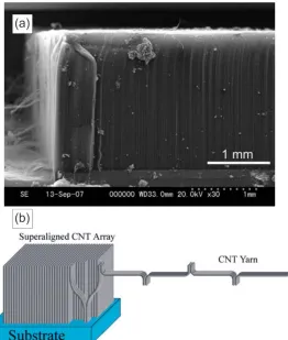
Figure 2.3 (a) SEM image of 2.1-mm-long VACNTs wafer (31) & (b) Schematic picture of the mechanism for drawing CNT from vertically aligned arrays (30).
affects the resulting spinnability of a grown array by means of CVD (33). The presence of several number of variables that critically affect the drawability of the VACNTs implies the fact that only few research groups worldwide are capable of achieving the aforementioned CNT spinnability.
Furthermore, based on the generally accepted notation, the critical issue for fabrication of spinnable CNT arrays is to have proper areal distribution density of uniform sized catalyst particles. In other words, the nanotubes have to be uniformly nucleated from densely distributed catalyst particle in order to have aligned, straight and spinnable arrays produced. To avoid time consuming pre-deposition of catalyst and buffer layers on substrate and to reach cost-effective CNT array growth methods with cheap precursors and simple procedures, the chlorine mediated CVD (CM CVD) method has been developed for growing spinnable CNTs where iron chloride powder FeCl2 is used as catalyst for nanotube growth (31). As this is the
specific synthesis method was used in this study, it will be further discussed below.
The growth method developed by Inoue et al. involves the synthesizing of vertically aligned ultra-long MWCNT using FeCl2 on bare quartz surface with the low pressure. This
catalyst has a dual catalytic activity. It reacts with carbon source, acetylene, in the gaseous phase, to nucleate Fe particles from which nanotubes grow in addition to dehydrogenating the carbon source to form active carbon species (31,34).
additional process for catalyst preparation as it only requires iron chloride powder and acetylene gas. Furthermore, the high dehydrogenation activity of iron chloride on acetylene increases the growth rate of CNTs compared to conventional pre-deposited metal catalysts due to the formation of Hydrochloric acid (HCl) as a by-product of acetylene dehydrogenation.
Hydrochloric acid showed the capability to enhance the Fe particles life activity by etching away the amorphous carbon from the catalyst surface and reacting with Fe to form more FeCl2 as the growth proceeds. It was found that the chlorine gas addition to the growth
have the same effect as HCl (34).
Figure 2.4 TEM images of MWCNTs grown by CM CVD method without (a) and with (b) chlorine gas added. Reproduced from (34).
it also suffers from the common CVD disadvantages like that the grown CNT tubes are not perfectly straight and can have more defects.
It is believed that the length of the individual CNT is a crucial element in determining the spinnability of the CNT arrays, however it turned out that there is an upper limit for the CNT length after which the drawability of the nanotubes is seriously affected (35,36). Furthermore, it was found that the type of the used growth method dictates to a great extent the CNT height upper limit. The decreased spinnability at longer growth lengths can be attributed to the formation of wavy CNT morphology which originates from the local inactivity of the catalyst particles. The local death of the catalyst particles causes the loss of the self-supporting network, necessary for the vertical growth of super aligned arrays (37).
The individual CNTs which have not yet died are then forced to occupy a larger radius of gyration before coming into contact with a neighboring CNT, thus creating the wavy CNT morphology. The decomposition and reaction of the lingering carbon during system cooling down was found to be another reason behind the formation of the CNT wavy structure at the bottom of the array near the substrate. The later finding highlights the influence of the manner by which growth of the entire array is terminated, on the CNT spinnability. A possible solution proposed in this study, was purging Argon gas following to the growth and during the cooling down period of the CVD system, so that the carbon precursor is quickly removed from the chamber before any further decomposition occurs.
The preferential alignment of the CNTs in one direction and their unique assembly consisting of millimeters long CNTs allows for the utilization of this morphology in a wide variety of applications (38). It worth adding that, it is impossible to produce CNT sheets with such unique features with conventional liquid based processing methods like acid functionalization, suspension, or wet spinning, These dry processing CNT assembly methods avoid the issues of nanotube degradation caused by chemical residual contamination and nanotube length reduction in some chemical and physical dispersion methods (39).
Additionally, the superior properties the CNT possesses have led to their study in many applications. For example, the high surface area and electrical conductivity of CNT sheets have made them useful in lithium-ion batteries and supercapacitors (40,41). Unidirectional thin layers of parallel aligned pure CNT sheets have also been used for the reinforcement of the high performance polymer matrix composites (42) and in solar energy harvesting devices (43,44).
With the large aspect ratio and excellent mechanical properties manifested in Young’s modulus and ultimate tensile strength as high as ~1,200 GPa and ~150 GPa (45), different CNT architectures were investigated in many research studies as a reinforcement phase in polymer (46), metal (47) and ceramic matrix composites (48). Furthermore, MWCNTs are considered to be weaker in tension compared to SWCNTs because of the slippage and pullout of the concentric walls. However, because of the relative ease of synthesis of MWCNTs, they are generally the reinforcement of choice for composites researchers.
include strength, stiffness (49–53), thermal (54–56) or electrical conductivity (57–59), wear resistance, toughness and many others. Due to their multifunctional nature, the carbon nanotubes, with their extraordinary physical properties, are believed to have the ability to yield an enhanced multifunctional composites by enabling the simultaneous tailoring of different properties (49,60–62).
With the unique structure of the CNT sheet assemblies readily drawn from the vertically aligned CNT arrays, they are expected to achieve progress in the development of well functional macroscopic CNTs sensing applications through exploiting the improved properties of the united nanoscopic individual CNTs (63–69).
2.3
Individual CNT Piezoresistivity
Piezoresistivity is a reversible phenomenon where the resistance of the materials changes with strain or deformation. Lord Kelvin first discovered it in 1856. This effect is due to the resistivity change due to stress associated with the pure geometrical effect caused by deformation. Therefore, the final resistance value depends on both bulk resistivity and the resistor dimensions. The intrinsic piezoresistive effect can be observed in semiconductors such as silicon where the resistivity changes as a function of strain. The resistivity of a semiconductor depends on the mobility of charge carriers.
It is reported that SWCNT band gap is dependent on the variation of diameter. Consequently, an increase in diameter leads to a decrease in the band gap (75). Therefore, CNT mechanical deformation alters the band structure of carbon nanotubes as a result of the CNT dimension change. Inter-atomic distance change causes the change in band gap. Depending on this change and the applied external load, it will be harder or easier for the electrons to be raised to the conduction band. This phenomenon will lead to a change in material conductivity and thus resistivity. This intrinsic piezoresistivity of carbon nanotubes can be very useful in the application of strain sensors.
Tombler et al. (70) prepared samples of individual single-walled CNTs with two ends covered by metal electrodes on SiO2/Si substrates. CNT length of about 605 nm was suspended
over SiO2 trenches (Figure 2.5). They reported that by using an AFM tip to manipulate the
Figure 2.5 Electromechanical measurements set up for a SWCNT with part of the length suspended over a trench: (a) Top view of the device, (b) AFM image of the CNT
& (c) Side view of AFM pushing experiment (taken from Tombler et al. (70)).
quasi-uniformly stretching the CNTs that were suspended on a micro-electromechanical machine (72). The quasi-metallic CNTs were found to have the largest piezoresistance gauge factors in the range of 600 to 1000.
Additionally, SWCNT bundles were pressed in the radial direction to study the piezoresistive properties (74). Expectantly, the behavior was more complicated in comparison to the performance of the single CNT. When pressed, the resistances of each CNT bundle exhibited different response which was explained by the different peizoresistive responses of each individual CNT in the bundles.
Numerous methods have been applied to fabricate nano-composites for strain sensing applications, yet, the fabrication of nano-scale CNT sensors based on individual CNTs suffers from realistic problems, such as, the complexity to apply precise manipulation and orientation to an individual nanotube. Furthermore, the inherent structural and electronic difference of the as-synthesized CNT is another example for the challenges facing the fabrication nano-scale CNT sensors.
Another difficulty arises from the fact that it is hard to align individual CNT on a large-scale due to their limited maximum length associated with the CNTs nanoscopic nature. Moreover, the morphology of as-synthesized CNTs show a great deal of variability and depend on the synthesis technique used to produce the nanotubes as well as the specific processing conditions (temperature, time, pressure), precursor materials (reactant gasses or solid carbon precursors), and catalysts (77).
in the failure of the device itself (78). Thereby, it doesn’t seem logical or practical to use individual CNTs as strain sensors with the associated aforementioned complications.
Accordingly, the main challenge for opening the avenue for using the CNTs in the strain sensing field is to scale their geometry and sensing properties up to meet the requirements of the structural health monitoring (SHM) domain. In this aspect, different researchers have attempted to manufacture CNTs ensembles for strain sensing applications.
Among the various manufacturing techniques implemented to fabricate nano-composites for sensing strain, three methods can be categorized as the principal types based on the mechanism and the principle used for strain monitoring. The first technique employed to fabricate CNT-based piezoelectric strain sensors used the electrospinning method (79).
Figure 2.6 Schematic drawing of electrospinning process (taken from Jialili et al. (79)).
The resulting CNT/PVDF thin film piezoelectricity increased 35 times by adding 0.05 wt.% of CNTs. Although the sensing capabilities of the CNT/PVDF composites were promising, however the application of this sort of fabricated CNT composite sensors is very limited since the properties are mainly dictated by the polymer solution. The advantages of the Raman-active properties of CNTs were the subject of the second type of CNT strain sensors. However, the permanent necessity to use large Raman spectra machines in examining structural health restricts the real application of this kind of CNT sensors since it is difficult to realize in-situ healthy monitoring.
to CNT electrical resistance change. By measuring the resistance of the deformed CNTs, the loading conditions of the composite structure can be determined. CNTs were first introduced into fiber reinforced plastics (FRPs) as sensors for SHM purposes by Fiedler et al. in 2004 (80).
Since then and because of the promising results, extensive research has been done recently on CNT/polymer strain sensors based on the piezoresistive effect. Given the convenience and ease of manufacturing, the major disadvantage was the low sensitivity as compared to individual nanotube sensors.
Figure 2.7 Number of annual journal publications and citations on the use of CNTs for damage sensing in composite materials (Taken from Zhang et al. (84)).
However before reviewing the recent research in which different macro-scale CNTs ensemble piezoresistive strain sensors were studied, a brief review for the current existing composite structure SHM techniques is necessary to survey their merits and disadvantages to highlight the motivation for the current research.
2.4
Current SHM Techniques for Composite Structures
2.4.1
Visual Inspection
Furthermore, there other assistant techniques that can be used to enhance the resolution and sensitivity of inspection such as coating the surface with impact sensitive coatings, using liquid penetrants and the usage of magnetic particles. One of the disadvantages of the visual inspection technique, beside the inaccuracy and limitation in detecting underlying flaws, is that disassembly of the parts is often required. In the aerospace industry, where safety is very crucial, the visual inspection of structural members and the required disassembly during scheduled inspection is an immense cost is labor intensive and time consuming (3).
2.4.2
Strain Gauge Methods
Strain gauges are peizoresistive metallic foil gauges that can only be mounted on the surface of the structures, otherwise they will act as defects. The strain is measured through change in the resistance as the voltage is applied across the foil gauge. Being, relatively small, inexpensive and simple to implement and relatively simple data acquisition are the merits of this strain monitoring technique.
However, due to size limitations, this method would require too many sensors as a single strain gauge can only cover a small region. Also metal foil strain gauges are not sensitive as their gauge factor is in the range of 2, which implies poor sensitivity to detect flaws such as micro-cracks (85).
2.4.3
Eddy Current
the electromagnetic induction phenomenon and is applicable to all electrically conducting materials. In eddy current testing, an AC current is supplied to a coil located near the testing structure. The eddy currents are produced by electromagnetic induction when a coil carrying AC current is brought near an electrically conducting material.
The magnitude of the AC current, distance of the coil from the material, presence of cracks, discontinuities in the testing specimen and physical properties of the examined material are the factors that the magnitude of the induced eddy current depends upon which in turn will affect the coil impedance. Consequently, the presence of defects in the inspected material impedes the eddy current flow and thus the impedance of the sensor changes. Hence moving the coil over the structure surface and monitoring the induced impedance change in the sensor can be easily correlated to the potential damage in the laminate and its locations.
The eddy current non-destructive technique is simple and does not require much equipment. However it also has few disadvantages such as, its usage is inclusive only to electrically conducting materials such as carbon fiber composites, it requires large amount of power and the produced data is difficult to interpret. It noteworthy that an automated SHM system using Eddy Currents has also been proposed in literature (86).
2.4.4
Ultrasonic Inspection
A pulser produces high voltage electric pulses which drives the transducer to produce high frequency ultrasonic energy. The acoustic energy is then propagated through the material in the form of waves. Similarly, when a defect or discontinuity is present in the wave path, a change in the acoustic impedance occurs and the wave are reflected back and received by the receiver. The reflected wave signal is displayed in the form of electrical signal. There are different types of ultrasonic scans. An “A” scan is similar to oscilloscope in terms of displaying a given time of the flight and the reflection amplitude data. The “C” scan displays pictorial plan view of the defects detected.
Immersion technique is one of the ultrasonic technique derivatives where transducer is recommended to be coupled to the specimen with water to enhance the sensitivity, however, this implies the obligation of removing the testing part from the structure and immerse it in the water.
2.4.5
Acoustic Emission
Acoustic emission (AE) is NDE passive method in which piezoelectric sensor is bonded on or embedded in a structure. It is based on the released energy waves in the presence of dynamic deformation. The propagating waves through the material undergo possible modifications before reaching the sample surface.
The piezoelectric sensor collects surface vibrations and amplifies them to produce the acoustic emission signals. The AE method is capable of detecting matrix cracking, fiber breakage, fiber pullout and delamination in composite materials. On the other hand, the limitations of AE technique include eliminating background noise, such as vibration induced noise, electromagnetic interference and transient noise. Another difficulty that mounting the AE inflight monitoring facility requires significantly more space compared to other SHM systems (1,3,87).
2.4.6
Optical Fiber Methods
Similarly, fiber optic sensors are passive and can be embedded in or surface mounted on structural materials. Fiber Bragg gratings optical fiber (FBG) can provide strain measurements of low bandwidth along one fiber optic cable in a large number whereas micro bend type fiber optic sensors are useful for monitoring bond lines and can sense both strain and pressure. FBG enables strain measurement using these passive sensors at a point much like a conventional resistance strain gauge.
composite structures which increases the operational cost along with the tendency to have complex connections. Furthermore, the introduction of optical fibers in composite laminates may lead to early matrix cracking because of the newly formed interfaces generated by these embedded sensors, resulting in weakening the composites in use which may limit their application in real structural components.
Fiber optics seem more suited to monitor strain at bridges and dams where the optical fibers can be placed at a large number of locations on these large structures. This help in avoiding long wiring and individual sensor installation in addition to justifying the high cost of this SHM system (1,85,87).
2.4.7
Radiography
Radiography is based on the fact that the presence of defects and variation in the structural integrity will create difference in the X-radiation absorption rate penetrated through the part being tested. With radiography, better images than with ultrasonic inspection are produced due to the usage of visual 2-D images.
and gives a better contrast. Nevertheless, there are few required conditions to strengthen the probability of detecting normally undetectable delaminations.
The first requirement is that the penetrant should be allowed to penetrate into the damage for about 30 minutes liquid and appropriate penetrant should be employed to avoid affecting the matrix properties.
2.4.8
Vibration-Based Methods
Vibration-based methods are fundamentally based on the principle that damage presence will cause detectable changes in modal properties such as natural frequencies, modal frequencies and mode shapes. Coin-tap testing is one of the most widely used and cost-effective vibration-based NDE techniques.
This method is based on the sound waves differential between defect and defect free region. However one of this method limitations is that the damage can be only detected when it is physically located immediately below the region stuck. The main principal of this method is using the changes in the natural frequencies to detect the damage because natural frequencies are convenient to measure from just few accessible regions on the structure and are usually less disturbed by external noise.
2.4.9
Electrical Resistance-based Methods
Another approach for damage detection is the use of carbon fiber composites to monitor the electrical resistance of the carbon fiber material. Damage would break fibers and cause the electrical resistance to increase. The advantage of this method is that the sensor is also an integral part of the structure, which makes this SHM method sometimes also called as “self-sensing” technique because the material itself acts as a sensor of its own damage (90–107). The self-sensing method can also be used to evaluate the interfacial properties of fiber reinforced polymer composites and it has several advantages compared to other non-destructive evaluation methods such as better stability, lower cost, and being rather simple (108).
Moreover, the electrical resistance change method does not require expensive equipment for instrumentation and does not cause any deterioration of the structure under monitoring and finally the structural weight is not changed (109).
Figure 2.8 Electric network of resistors, representing a preform of carbon fibers in an insulating matrix (taken from Park et al. (110)).
The difficulty to electrically contact the composite and the relatively low damage sensitivity are one of the common limitations that comes into the picture while implementing this technique. The low damage sensitivity can be attributed to the presence of millions of parallel micro fibers in the composite structure and damage to a small number of fibers has a small effect on the overall resistance because the fibers are like parallel resistors that can also conduct laterally.
Carbon fibers also do not exhibit a tailorable piezoresistive effect like carbon nanotube assemblies (85). Finally, one of the major disadvantages, is that this technique is ineffective with insulating fibers such as glass fibers which implies the need for external sensors to monitor damage in glass fiber plastics with the associated attached alteration of mechanical properties and increased cost.
Accordingly, there is a growing interest in techniques that do not require additional sensors to study composite behavior with the desire to develop an in-situ self-detecting function. This can be achieved either through the introduction of conductive nano fillers in the polymer matrix or surface functionalization of reinforcing fibers with conductive nano fillers. Adding a small amount of CNT to form an electrically conductive network has been found to be a promising approach for monitoring damage initiation and propagation in all types of fiber reinforced composites.
As micro-cracks propagate in the matrix, the conductive pathways are disrupted in the percolating network, resulting in changes in electrical resistance. The CNTs concentration in the composites interphase results in significantly improved mechanical properties and electrical conductivity (113).
2.5
CNT/Polymer Composite Sensors for Damage and Strain
Sensing Applications
With the previously discussed unique piezoresistive sensing response of CNTs (63,83,114–116), CNT composites can be utilized as in-situ strain sensors when integrated directly into the structural material (5,117–120) or as ex-situ sensors that can be attached to a structure (i.e., strain sensors (63–68) or body motion sensors (121,122)).
(50,63,64,66,68,77,83,123) and (2) the intrinsic piezoresistivity of CNTs themselves, as load is transferred to the nanotube via the interface of the polymer (65,66,124).
Furthermore, the potential for the CNT-based sensors to offer SHM functionality was proven in different studies (5,62,117,118,125,126). This was made possible through; (1) measuring the overall electrical resistance change in the strained nano-composites and correlating this change to the strain and (2) quantifying and real-time monitoring of the onset, nature, and evolution of damage in the nano-composites. In the coming sections, we will review the typical approaches used to fabricate CNT macro-scale architectures and show some representative results with the aim of highlighting the potential of percolated CNT networks to function sensory systems.
2.5.1
CNT/Polymer Hybrid Fibers
Figure 2.10 SEM image of the PVA-CNT fiber (a) surface and (b) cross-section. (c) Manufactured GFRP plate with embedded PVA-CNT fiber and wiring for resistance
measurements (127).
The sensor showed a gauge factor of nearly 2 during real-time sensing when the structure was subjected to cyclic loading. The observed residual electrical measurements of CNT fiber reflected possibly self-damage corresponding to almost 45% of fracture stress of the material which highlight the ability the PVA-CNT fibers to predict the structural failure by residual electrical signals.
2.5.2
CNT Coated Fibers
CNTs grafting onto fiber surfaces has been also used to create electrically conductive interphases for introducing sensing capabilities into bulk nano-composites. The morphologies of CNT coatings on the glass fiber surface were investigated using scanning electron microscopy (SEM). The SEM image shows that the CNTs may be well dispersed and distributed on the glass fiber surface.
Figure 2.11 Typical SEM images of different glass fibers: (a) Without coating, (b) With coating containing 0.12 wt.% CNTs & (c) With coating containing 0.50 wt.% CNTs)
in composite structures (131). To coat the fiber, the electrophoretic deposition (EPD) technique was used to drive the negative charged CNTs towards the anode through glass fibers.
As observed in their research, nanotubes penetrated into the space between fibers and coagulated on the fiber surface, achieving a good adhesion to the glass fibers as shown in Figure 2.12a. After the CNTs were applied onto the surface of glass fibers, the entire assembly was embedded into epoxy resin.
Figure 2.12 (a) Schematic of micro-crack bridge in epoxy composite with a MWCNT coated fiber and (b) In-situ damage sensing on single glass fiber with CNT coating via EPD. Different stages of fiber tensile loading are shown in the graph together with the
Because the CNTs are well dispersed on the glass fiber surface with good contact between the nanotubes and the glass fibers, the breakage of the fibers would effectively induce the entire or partial fracture of CNTs coating them. After the sensing performance was evaluated, as shown in Figure 2.12b, a combined three stages with a linear, nonlinear, and abrupt change were discovered.
The linear and nonlinear piezoresistive responses were discovered before the structures fracture at lower strain level. Then, a significant electrical resistance increase occurred suddenly showing the fracture of the nanotube network coated on the glass fiber surface which indicates the possibility of using this multifunctional layer as a mechanical sensor.
In another study, Zhang et al. (132) compared dip-coating technique to the EPD method. The results showed that the EPD showed improved dispersion of CNTs on glass fiber surfaces compared to dip-coating and more than 30% increment in interfacial shear strength compared to the reference system was reported. It worth noting that a large scatter in electrical resistivity was measured in this study for the similar CNT loading specimens (84).
Moreover, it was concluded that the dip-coating led to the reduction of the single fiber tensile strength. The findings of these studies draw the attention to that; achieving stable and repeatable sensing signals and avoiding the degradation of original material properties, are prime key factors in successful in SHM applications.
This model study confirmed the possibility of using CNTs directly onto insulating fibers such as glass fibers to produce multifunctional composite, however the strength and other mechanical performances were not measured in this research work, and the use of surfactant, pH control, as well as the complicated manufacturing procedure may limit the scaling-up.
The potential use of cotton natural fibers in the electrical textile area was investigate by Kang et al. (134) in which SWCNTs were coated on common cotton yarns. Nanotubes were first dissolved and dispersed into the solution, following which dipping and drying processes were applied to coat the cotton yarns with SWCNTs.
This type of sensors showed high but negative gauge factor of -24 which can be possibly explained by the transverse contraction induced by the longitudinal stretching of cotton yarns. In this case, the CNTs come closer to each other and result in a reduction in the CNT network overall electrical resistance because of the newly created electrical pathways. The pretty high sensitivity of this sort of sensor (approximately 12 times more sensitive than traditional metal foil strain gauge), emphasize the potential use of this modified cotton yarn as a strain sensor and also in the smart fabrics application.
strength reduction of the original fiber as well as issues related to complex additional processing steps.
2.5.3
CNT/Polymer Hybrid Composite Film
Two-dimensional sensors have been more widely investigated because these assemblies possess large amount of nanotubes which may provide significant large inter-nanotube connections, leading to the formation of sufficient conductive pathways which can in turn enhance the electron conduction. Furthermore, these types of sensors are more compatible for multi-direction and multi-location use compared to one-directional sensing materials discussed earlier.
Figure 2.13 SEM images of glass fibers with CNT coatings, solid coating content on glass fiber is 5.5 wt.%: (a) Coated glass fiber, (b) Higher magnification of coated glass
fiber with CNTs dispersed in PP particles of the film former, (c) Glass fiber after annealing at 200 °C for 15 min & (d) Charge contrast SEM image of CNT coating after
annealing (136).
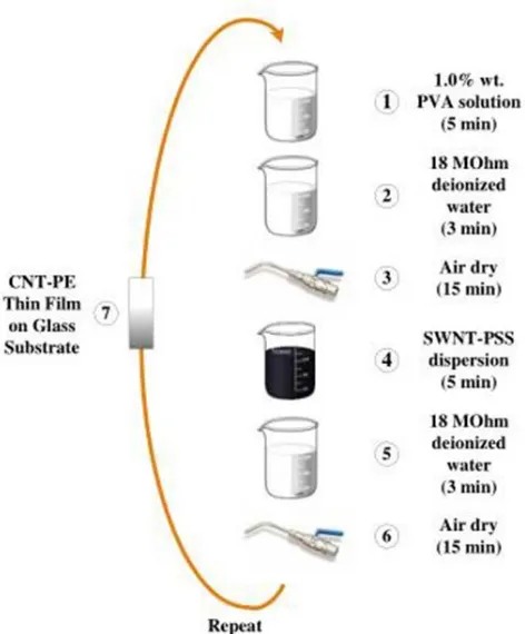
Loh et al. (114) fabricated a carbon nanotube-polyelectrolyte (PE) composite multi-layer thin film by a multi-layer-by-multi-layer (LbL) method, shown in Figure 2.14. In that research, a diverse suite of CNT-PE thin films composed of varying combinations of types of CNT, types of PE, and CNT concentration are fabricated. A very long sonication process was applied to disperse carbon nanotubes in a high molecular weight poly (sodium4-styrene-sulfonate) polyanion solution.
It was concluded that with increasing CNT concentration, one can progressively increase the strain sensitivity of the macro-scale multi-layer film. The CNT-PE film displayed time variant exponential decay of bulk film resistivity and a higher current caused a faster resistance decaying.
Figure 2.14 Illustration of the layer-by-layer deposition of CNT-polyelectrolyte thin film using self-assembly process (taken from Loh et al. (114)).
Vacuum filtration and molding transfer techniques were used (138) to fabricate MWCNT/PDMS hybrid film. Once the MWCNTs suspension was made by sonication method, it was vacuum filtrated into the mold with highly uniform nanotube dispersion. After the film was formed and transferred to the PDMS substrate, another thin layer of PDMS was applied as a package covering the CNT film to enhance the adhesion of the silver paste and prevent surface contamination as shown in Figure 2.15.
Figure 2.15 Schematic diagram of CNT/PDMS hybrid thin film (138).
Another recent interesting approach was the manufacturing of multi-layer stacked aligned transparent CNT films for strain sensing by K. Liu et al.(139). The super aligned CNT (SACNT) film described in their research work was drawn out from a 190 µm tall CNT forest grown by chemical vapor deposition method. Multiple layers were laid one by one following a pre-designed orientation and densified through a dipping process (Figure 2.16a-b).
Figure 2.16 Schematics of manufacturing of the super-aligned, transparent, flexible and stretchable SACNT/PDMS composite film (139).
The as fabricated CNT films were further embedded into a flexible PDMS composite structure shown in Figure 2.16c. Despite that the gauge factor of this composite sensor was ~1.17, however it exhibited much better conductivity (resistivity ~10-4 Ω cm) compared to randomly distributed CNT/polymer composites due to the biased alignment and orientation of the CNT in the investigated composite sensors. This unique feature may favor the application of this sort of sensors in smart electronic device fields.
Generally speaking, the two-dimensional sensor are more feasible and reliable to handle different load conditions because they favor the multi-direction and multi-locations testing at the surface of target laminate. Moreover, they readily can be mounted onto the surface of host materials/structure of different geometries without deteriorating the mechanical integrity and can even impart additional functionalities.
However, these small film sensors can only manage local strain/stress monitoring and the performance stability is questionable, because different gauge factors ranging from less than 1 to 10 were reported by different research groups.
2.5.4
Three-dimensional CNTs Dispersed Bulk Composites
The exploitation of various unique properties of CNTs in composites depends strongly on how the CNTs are integrated into the three-phase multiscale composites. Modifying the matrix resin by dispersing CNTs in the polymer offers the most conventional, facile and industrially compatible route. Additionally, some promising improvements in matrix dominated mechanical properties have been observed through the dispersion and infusion approach for reinforcing the matrix throughout the fiber composite.
MWCNTs were dispersed into the epoxy resin using a calendaring approach to fabricate CNT/epoxy fiber composites (62). The percolating network of sensors was created and the cured composites laminates were machined into test samples for sensing measurements. The stress transfer was enhanced by combining micrometer sized glass fiber and nanometer scale CNTs that effectively filled the areas between matrix and fibers.
The initial stages of matrix dominated failure were detected in-situ by monitoring the strain of the composite and the resistance change at the same time. Thostenson and Chou (140) in another study, presented the resistance hysteresis for a specimen undergoing 25 cycle of strain loading prior to fracture. The remarkable spikes in the sensing curve indicated the permanent bonding damage between the matrix and the CNTs. However, the formed CNT sensor network showed some degree of failure after two cycles of loading which caused the permanent resistance increase of the composites. The permanent damage of the CNT network is a great challenge, which limits the real application of the carbon nanotube-based strain sensor due to the very limited accurate strain sensing range.
Figure 2.17 Schematic of fabrication procedure of MWCNT/PC composite strain sensor including wet mixing and casting (taken from Zhang et al. (124)).
Knite et al. (141) mixed MWCNTs in polyisoprene matrix and the mixture was vulcanized under high pressure in an attempt to develop new nanocomposite for sensing strain. The specimens were tested under both, small and large strains. While the resistivity was very reversible under strain of 4%, a relatively large hysteresis of resistivity was observed when the samples were 40% stretched and released which is one of the challenges encountered in strain sensing by means of CNT networks.
Thostenson and his group (62) dispersed MWCNTs into epoxy and infused into a physically treated glass fiber preform to form a conductive percolating network only at a very low CNT concentration. The purpose of the physical treatment was to achieve a good nanotube distribution. The nanotube network throughout the whole composite polymer matrix system showed great sensitivity to initial variations of subtle matrix dominated failure and were capable of evaluating the onset and evolution of damage in composite structures.
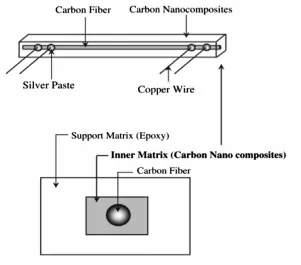
manufactured. In order to obtain damage sensing results, they combined the electrical sensing method together with traditional AE. During tensile loading along the fiber direction, fiber breakage occurred and electrical sensing signals as well as AE signals were collected.
Figure 2.18 Experimental setup of double-matrix single carbon fiber composites (taken from (143)).
percolating CNT network within the matrix. Hence, after initial fiber fracture, the electrical signals progressively increased with the strain increase, revealing more internal damage information which was confirmed by the AE data. At higher CNT loadings (2.0 wt.%), the measured sensitivity during the test was obviously lower than that for the 0.5 wt.% specimen which was attributed to the higher number of possible contact points in this percolated CNT network.
Ku-Herrera et al. (144) studied the electrical sensitivity of glass fiber/MWCNT/vinyl ester hierarchical composites capability of self-sensing the accumulated structural damage when subjected to cyclic tensile loading-unloading. The hierarchical composites were designed to contain two different locations of MWCNTs, viz. MWCNTs deposited on the fibers and MWCNTs dispersed within the matrix.
Figure 2.19 Schematic for the hierarchical composite structures: (a) MWCNTs dispersed in matrix & (b) MWCNTs on the fibers (144).
upon unloading characterized the damage accumulation associated to matrix dominated irreversible phenomena such as yielding and viscoelasticity. On the other hand, the composites with MWCNTs deposited onto the fibers showed a positive permanent change in electrical resistance upon unloading, which was associated to fiber/matrix debonding and fiber breakage. Furthermore, the composites architectures with MWCNTs on the fibers was very sensitive to fiber dominated damage mechanisms. They were able to detect the onset of composite damage by a deviation from linearity and hysteresis in the electromechanical curve, as well as to detect damage progression (144).
There is no doubt that the CNT dispersion approach for producing CNT based strain sensors has drawn the most attention and effort with the large amount of associated research work done and still going on. However, there are still major rational concerns that alter the performance of the CNT sensors formed by dispersing CNTs into the matrix. Examples include, the lack of uniform dispersion, random nature of the CNT dispersion, the breakage of CNTs during processing and the weak CNT/polymer interface. Among the major concerns is also the higher tendency of the CNTs to form agglomerates in the polymer matrix due to their strong van der Waals interactions and the associated dramatic increase in the viscosity of the matrix even if a very small CNT content (below 1 wt.%) is added to it (145).
N. Hu et al. (83) used a novel dry mixing technique (a planetary mixer) to directly mix MWCNT, epoxy resin and the hardener altogether. This method is highly controlled by merely adjusting the speed of the mixer, achieving different level of CNTs dispersion.
Figure 2.20 Schematic of the planetary mixer (83).
In this research, they compared the piezoresistive sensing behavior of specimens made with different mixing speed. Higher stirring or mixing rate was suggested to improve the sensitivity, possibly due to the fast mixing which may induce good dispersion of nanotubes and thus good conductivity.
2.5.5
Pristine CNTs Assemblies
2.5.5.1 CNT Yarns Strain Sensor (One-dimensional Assembly)
individual CNT being strong, stiff, light, small, corrosion resistive, electrical and thermal conductive. They can also be embedded into composite structures without deteriorating the structural integrity and thus can function as effective strain and damage sensors (81,146).
Figure 2.21 (a) SEM image for CNT yarn spinning from the as-grown CNT forest, (b) Schematic for the Al electrodes deposition on a CNT yarn using magetron sputtering
(81) & (c) Schematic of the side and cross-section of the laminated composite sample with transversely stitched CNT yarns under simultaneous three-point mechanical and
two point electrical measurements (1).
monitoring. Zhao showed only a gauge factor of pure yarns at ~0.5 for both monotonic and cyclic tensile testing.
Using a different fabrication method shown in Figure 2.21c, Abot et al. (1) wrapped CNT yarns into a needle and then transversely stitched them throughout the central plies of the composite laminate. Although low gauge factors were observed, however, a systematic aggregation of multiple CNT yarns placed in different locations may be able to effectively monitor the propagation of cracks in the composite structure by observing the sudden resistance increases due to crack propagating across the yarns.
2.5.5.2 CNT Film or Bucky Paper (Two-dimensional Assembly)
Figure 2.22 SWCNT film with insulating PVC film attached to the brass specimen (65).
They observed a nearly linear trend in the film resistance response when subjected to tensile and compressive cycles within ±0.02% strain. During the cyclic tensile and compressive testing, the voltage changes across the specimens were measured with a four- probe method in-situ.
Similarly, Kang et al. (67) dispersed commercially obtained SWNTs in DMF solvent in a bath sonicator for 20 hours. The SWNTs suspension was then poured into a filter paper and dried in an oven for 12 hours. After that the bucky paper was peeled off and characterized by electrochemical impedance spectroscopy. To improve the piezoresistance consistence, PMMA was added to the SWNTs suspension.
from of 1.0 to 5.0. The produced strain sensor was long and continuous at a low cost, which may be suitable for potential SHM applications.
2.5.6
CNT Coated Two-dimensional Assembly
Dai et al. (150) introduced a simple method to fabricate CNT-based nonwoven composite strain sensors. A relatively small concentration of CNTs of approximately 1.0% by weight are deposited from an aqueous solution onto a selected nonwoven carrier aramid fabric, followed by infusing an epoxy resin into the CNT-modified nonwoven fabric to hold the CNT network in place.
The approach simplicity and the relatively small concentration of the CNTs may allow for scaling this technique up for large-scale monitoring in addition to being a cost-effective method. They succeeded in producing an electrically isotropic nanotube network on the surface of the fibers. After the nonwoven composite sensor strain sensitivity was characterized in-situ, the proposed sensors were bonded onto metal substrates, including aluminum and steel and tested under quasi-static cyclic tensile and compressive loads.
Figure 2.23 Photograph showing a free-standing CNT sensing composite after curing the epoxy, showing its flexibility (150).
2.5.7
CNT sheets
Li et al. (151) developed an aligned sheet of interconnected CNTs drawn from a chemical vapor deposition grown CNT array which was embedded in a single layer glass fiber/epoxy prepreg and then the entire assembly was bonded to the surface of glass fiber/epoxy composite host coupons.
The results confirmed that the CNT sheet orientation had a dramatic effect on the sensor strain sensitivity thus confirming the anisotropic sensing performance of the CNT sheet sensor. Furthermore, the CNT sheets exhibited good sensing stability, linearity, sensitivity and repeatability within a practical strain range along with good intrinsic piezoresistive stability and a reversible resistance change when the fabricated sensor was exposed to changing temperature (151).
Finally, they found that the pre-straining process improved the piezoresistive performance of the CNT-based sensor, producing a closer to linear behavior over an even wider strain range. However, the fabricated sensor suffered from gradual damage in the conductive nanotube network upon being subjected to 1000 cycle fatigue test.
Table 2.1 Summarizes the manufacturing techniques and the significant results of different studies that investigated the composite strain and damage sensing work via
CNT networks (taken from Zhang et al. (84)).
Fiber/Matrix Nanofillers (loadings) and location Manufacturing processes Detected failure and damages Main results Glass fiber (GF)/epoxy (62) MWCNTs (0.5
wt.%) in epoxy Three-roll mill
Delamination and
micro-cracking
Showed possibility of using CNTs to
identify different failure
modes
GF/epoxy (131) MWCNTs on GF surface Electrophoretic deposition (EPD) Micro-cracking Coated single GF as in-situ
sensor for tracking micro-cracks GF/epoxy (117,140) CNTs (0.5
wt.%) in epoxy Calendering
Crack initiation during static and
incremental tensile loading Used CNT networks to identify different failure stages GF/vinyl ester (125) CNTs (0.5
wt.%) in matrix Calendering
Crack initiation during static and
incremental tensile loading
Combined with AE, it showed
some advantages of
the electrical sensing method
GF/epoxy (152) MWCNTs (0.3
wt.%) in epoxy Calendering
Crack initiation during tensile
loading
Used CNTs to identify damage
initiation
GF/epoxy (75) SWCNT on GF
surface Spray coating
Table 2.1 Continued
GF/epoxy (153) MWCNTs (1.0
wt.%) in epoxy Three-roll mill
Localization of failure under tensile loading Localized failure by placing electrodes at different positions
GF/epoxy (154) MWCNTs (0.5 wt.%) in epoxy
Three-roll mill and sizing agent
Sensing under tensile loading Compared effect of dispersion and CNT localization on sensing data GF/epoxy (155) CNTs (0.1/0.5/1.0 wt.%) in epoxy
Calendering Sensing under
tensile loading Improved sensing signals for CNT-modified specimen
GF/epoxy (156) MWCNTs (0.5
wt.%) in epoxy Sonication
Sensing under tensile loading Improved sensitivity for CNT-modified carbon fiber reinforced plastics (CFRPs) compared to neat CFRPs GF/PP (135,136,157) MWCNTs (0.5 wt.%) in polymer film coated on
GF
Sizing or coating of CNT/polymer
film onto GF
Interface strain sensing under tensile loading Alternative route utilizing aqueous CNT/polymer coating on GF for sensing
GF/epoxy (142,143)
CNTs (0.1 to 2.0 wt.%) in
epoxy Solution-based processing Fiber breakages in dual-matrix composites
Table 2.1 Continued
GF/epoxy (158) CNTs (0.5 wt.%) in epoxy
Solution-based processing Fiber breakages in dual-matrix composites Showed effect of CNT dispersion on sensing results
GF/epoxy (159) MWCNTs (0.3
wt.%) in epoxy Three-roll mill
Sensing during interlaminar shear strength testing (ILSS) In-plane sensing signals gave sudden increase at failure, while through-thickness signals showed no obvious changes during testing GF/epoxy (127–129)
CNTs in PVA fiber CNT/PVA fiber strain sensor Strain sensing under tensile and three-point bending test conditions
Use of a CNT/PVA fiber
as embedded strain sensor in
GFRP
GF/epoxy (126) MWCNTs in epoxy Dispersed in epoxy using sizing agent Impact damage Showed potential of electrical sensing method for impact damage
GF/epoxy (160) CNTs (0.1–0.5 wt.%) in epoxy
Mechanical stirring and sonication Impact damage Showed increased resistance after impact damage
GF/epoxy (161) MWCNTs (0.5
wt.%) in epoxy As-received Impact damage