ABSTRACT
BHAGWANANI, SANGEETA. An Evaluation of End-User Interfaces of Scientific Workflow Management Systems (Under the direction of Dr. Mladen Vouk).
Scientific research is often exploratory in nature. As technology advances, more steps of such work may become automated. Data used and produced in such experiments becomes increasingly complex and heterogeneous. In such scenarios, a need arises for a tool (or a set of tools) that allows dynamic modeling and (semi) automatic construction and integration of problem solving flows (scientific workflows) using various, often network-based, components.
SciDAC’s Scientific Data Management (SDM) initiative is developing a framework that allows scientists to manage data in a more efficient manner, using tools that help them create and manage scientific workflows that use network-based (web) services. This work is part of that effort and it focuses on a comparative analysis of user interfaces of the SDM framework with some other available solutions. An approach for evaluating SWFMS end-user interfacing is presented. More than 20 criteria, based on HCI literature, and interviews, and the findings from the prototype SWMS developed as part of SDM research, are presented. The criteria are used to compare and discuss interfaces of the current version of the SDM SWFMS – the Scientific Process Automation system based on Ptolemy II framework, with some other open-source systems intended for high-end scientific workflow support, such as SCIRun, Enhydra JaWE, and Taverna.
AN EVALUATION OF END-USER INTERFACES OF SCIENTIFIC WORKFLOW MANAGEMENT SYSTEMS
By
SANGEETA BHAGWANANI
A thesis submitted to the Graduate Faculty of North Carolina State University
in partial fulfillment of the requirements for the Degree of
Master of Science COMPUTER SCIENCE
Raleigh 2005 APPROVED BY:
________________________________ _______________________________ Dr. Christopher G. Healey Dr. Peter Wurman
________________________________ Dr. Mladen A. Vouk
BIOGRAPHY
Sangeeta Bhagwanani was born in Muscat, Oman. She completed her education in India,
and received her Bachelor’s degree in Computer Science from M. S. University, India.
She joined the Master’s program in Computer Science at NC State University in Fall
ACKNOWLEDGEMENTS
I express my sincere gratitude towards the Chair of the Advisory Committee of my MS
Thesis, Dr. Mladen Vouk, for his guidance, support and encouragement since I have been
a part of the research group. I also thank Dr. Robert St. Amant, Dr. Peter Wurman and
Dr. Christopher G. Healey for serving on my thesis committee and guiding me through
various parts of it.
Special thanks to my colleagues, past and present, at the SDM group at NC State for their
support and help throughout the research and writing of my thesis. Zhengang Cheng has
been an excellent person to work with and has always helped me with various different
aspects of this project. I also thank my colleagues at San Diego Super Computer Center,
Georgia Tech and Lawrence Livermore National Laboratory for their cooperation.
I would like to thank my family, for their constant encouragement and faith in me. Their
support means a lot to me. And last but not the least, many thanks to all my friends for
their help, support and confidence.
This work has been supported by the DOE SciDAC grant DE-FC02-01ER25484 and
TABLE OF CONTENTS LIST OF FIGURES viii
LIST OF TABLES ix 1 INTRODUCTION 1 1.1 MOTIVATION 1
· Data post-processing: 4
· Real-time simulation analysis: 4 1.2 SCOPE 5
1.3 RELATED WORK 6
1.4 ORGANIZATION OF THE THESIS 8 2 ARCHITECTURE AND CONCEPTS 9 2.1 WORKFLOW CHARACTERISTICS 9 2.2 SERVICES 10
2.3 REPOSITORY 11
2.4 GRAPHICAL USER INTERFACES 12
2.5 SCIENTIFIC PROCESS AUTOMATION (SPA) 13 2.5.1 Background 13
3 USER INTERFACE DESIGN PRINCIPLES AND EVALUATION 16 3.1 USABILITY 18
3.1.1 Windows and the WIMP interface [DFAB97] 19 3.1.2 Metaphor [All01] 19
3.1.4 Direct Manipulation 20
3.2.1 User-Centered Design 22 3.2.1 Iterative Design 23
4 EVALUATION HEURISTICS 24
4.1 HEURISTIC EVALUATION PROCESS 26 4.2 USABILITY HEURISTICS AND METRICS 28 4.2.1 Construction and Execution of workflows 28
4.2.2 Match between system and real world [DFAB97, NM94] 29 4.2.3 Ease of Use 29
4.2.4 Flexibility and efficiency of use 30 4.2.5 Consistency and Standards 31
4.2.6 Recognition rather than recall 31 4.2.7 Aesthetic and minimalistic design 32
4.2.8 Employing dialog to resolve key uncertainties 32
4.2.9 Interaction with the end-user and Visibility of System status 32 4.2.10 Allowing efficient direct invocation and termination 33
4.2.11 Interaction with a Central Repository 33 4.2.12 Data-Mapping 34
4.2.13 Decision-based execution 35 4.2.14 Visualization of output data 35 4.2.15 Reusability of Workflows 36
4.2.16 Verification, Validation and Fault-Tolerance 36
4.2.19 Security and Protection 37 4.2.20 Web-based GUI 38
4.2.21 Interoperability 38 5 THE PILOT SYSTEM 40
5.1 THE SDMSDWE SYSTEM 40 5.1.1 Using the SDMSWE system 43
5.1.2 The SDMSWE Graphical User Interface 45 5.2 LESSONS LEARNED FROM THE PILOT 47
6 A COMPARATIVE EVALUATION OF SCIENTIFIC WFMS 50 6.1.1 Main features of Ptolemy II 52
6.1.2 The SPA system 53 6.1.3 Some Usability Issues 56
6.1.4 Other evaluations of SPA 58
6.2 AN EVALUATION OF SCIRUN 60 6.2.1 The SCIRun User Interface 61
6.2.2 Modules 62 6.2.3 Pipes 63
6.2.4 Some Usability Issues 64
6.3 EVALUATION OF ENHYDRA JAWE 66 6.3.1 Package Level 66
6.3.2 Process Level 67
6.3.3 Some Usability Issues 69
6.4.1 The Bonita Modeling Component 71 6.4.2 The Bonita Execution Component 72 6.4.3 Some Usability Issues 75
6.5 AN EVALUATION OF TAVERNA 76 6.5.1 The Scufl Workbench 77
6.5.2 Some Usability Issues in Taverna 79 6.6 A COMPARISON 81
6.6.1 Discussion 82 7 CONCLUSION 85 7.1 SUMMARY 85 7.1.1 Contribution 88
7.2 FUTURE WORK 89
REFERENCES 91 APPENDIX 98
I PROMOTER IDENTIFICATION WORKFLOW 98 II TSI WORKFLOW 100
LIST OF FIGURES
FIGURE 2.2.1: PIW WORKFLOWS AND SUB-WORKFLOWS AS IMPLEMENTED IN THE SPA SYSTEM 15
FIGURE 3.1.1: NORMAN’S EXECUTION-EVALUATION MODEL [NOR] 17 FIGURE 5.1.1: ARCHITECTURE OF SDMSWE 41
FIGURE 5.1.2A: SDMSWE SCREENSHOT 45 FIGURE 5.1.2B:EXECUTION IN SDMSWE 47
FIGURE 6.1.1: SCREENSHOT OF A SIGNAL PROCESSING WORKFLOW IN THE PTOLEMY II ENVIRONMENT 53
FIGURE 6.1.2: SCREENSHOT OF THE HIGH LEVEL PIW IN THE SPA ENVIRONMENT 56
FIGURE 6.2.1: THE SCIRUN WINDOW FRAME [SCIRUN04] 61 FIGURE 6.2.2: SCIRUN SAMPLE WORKFLOW [SCIRUN04] 62 FIGURE 6.2.3: ANATOMY OF A SCIRUN MODULE [SCIRUN04] 63 FIGURE 6.3.1: PACKAGE LEVEL IN JAWE [JAWE04] 67
FIGURE 6.3.2: PROCESS LEVEL VIEW IN JAWE [JAWE04] 68 FIGURE 6.4.1: BONITA GRAPHEDITOR TOOL [BONITA04] 72 FIGURE 6.4.2: BONITA ACTIVITY EXECUTION [BONITA04] 73 FIGURE 6.4.3: BONITA WORKLIST EXECUTION [BONITA04] 73 FIGURE 6.4.4: THE BONITA ARCHITECTURE [BONITA04] 74 FIGURE 6.5.1: TAVERNA ARCHITECTURE [TAVERNA04] 76
LIST OF TABLES
1 Introduction
Scientific research is exploratory in nature. Scientists carry out experiments, often in a
trial and error manner, wherein they modify the steps of the task to be performed as the
experiment proceeds. As technology advances, more and more scientists are relying on
computing systems to aide them in such explorations and problem solving.
The scientist typically divides up the overall task into smaller sub-tasks, each of which can be
considered to be an individual step in an experiment. The results obtained from each such step
are either analyzed and/or stored for dissemination to other sites or individuals, or are used as an
input to the next step in an experiment or exploration, or both. Such a reuse of data can be done
repeatedly until the overall task is completed to the scientist’s satisfaction. We call such a
chaining of smaller tasks together to achieve desired results from the experiment or explorations,
using various data and analysis services, a “workflow” [SV96, All01].
1.1 Motivation
For example, an NC State astrophysicist may develop a simulation package that needs to run on
a highly parallel supercomputer. The output from the simulation needs to be manipulated to
produce correct time-step mergers and prepare it for visualization display. This visual output
then needs to be studied, parameters may need to be changed, simulations may need to be re-run,
new data may need to be stored, and so on. If such a computer is not available locally, the
scientist may need to run at a remote site, perform data post-processing either remotely or
otherwise analyze the results. The issue that arises (in this particular example) is that a
supercomputer simulation can produce as much as 1 Terabyte of data overnight. While the
scientist would like to view the results in the morning, today this is not really possible for a
variety of reasons (e.g., security at remote site, amount of data, software licenses). On the other
hand, bringing the data over to NC State may be an equally laborious task. It may involve
constant attention and re-runs of data transfer commands, and so on. A lot of someone’s time
may be spent on this. Automation of the whole process, from simulation submission to final
preparation of the outputs for visualization, is desirable.
Similar workflows, but with other issues, can be found in almost any domain of scientific
discovery [DOE04]. There are many commonly occurring scenarios in scientific domains of
interest that can be automated using a sufficiently robust and flexible workflow infrastructure.
The characteristics of workflows that may benefit from a proper workflow environment include
the rate, coupling, and synchrony at which workflow elements (tasks) exchange data. Depending
on the application, dataflow rates range from very low (in kilobits per second) to very high
intensity (in gigabits per second). There is a range of coupling - judged mostly by the allowable
transfer delay per unit of data – from tightly coupled, requiring microsecond delays, to loosely
coupled, allowing milliseconds and even seconds of delay. Finally, there are synchronous (or
blocking) and asynchronous (or non-blocking) flows. More concrete scenarios where workflows
could be applied include:
Genomics data analyses often have dataflows that are of low to medium intensity, relatively
genomics analyses, such as promoter identification, start with an initial set of data, perhaps
acquired in a more mechanical way such as through fast sequencing equipment or from a
microarray chip. This is followed by an ordered sequence of database queries, data
transformations, and complex functional, statistical and other analyses. Such work may require
computing power that ranges from a desktop to a supercomputer, but typically interchanges data
only in the megabyte to gigabyte range. By defining a workflow to automatically invoke and
analyze more routine parts of the process, multiple data sets can be processed in parallel without
requiring a significant amount of additional effort from the scientist and can considerably
increase productivity [Cha02]. The bioinformatics workflow we have used so far in this project
is described in more detail in Appendix I.
Leading-edge simulation analyses typically belong to the high-intensity data flow category –
they not only require high performance computers, but produce and exchange data from
hundreds of gigabytes to terabytes, and perhaps even petabytes, of data. Because these scenarios
are resource intensive, prudent computational planning, steering and validation of the workflows
(whether manual or automated) is necessary. At the beginning, flows tend to be tightly coupled
and synchronous. However, as the scenario progresses they may well be both asynchronous and
• Data post-processing:
When a scientific simulation is completed, a sequence of tasks is often executed by the
scientist to analyze the resulting data set(s), e.g. run an analysis to check for errors, eliminate
corrupted time-steps, identify the interesting subset of the data, visualize the data, generate a
movie, and transfer the data set to long-term storage or a data-distribution depot. Of course
the details vary but for each scientist the sequence of tasks remains relatively consistent
across simulation executions. By providing an easy way of automating, tracking and
modifying this sequence of tasks, data post-processing may be more performed more
efficiently in our experience as much as an order of magnitude more efficiently [Cha02].
• Real-time simulation analysis:
While a simulation is executing, a series of analysis steps can be performed to determine if
the run is proceeding as expected or has encountered an erroneous condition (e.g. a tangled
mesh, a singularity, etc.). Based on the results of this analysis, a scientist can modify or
terminate the execution of the simulation and thus reduce the time spent performing wasted
computations. While creating and automating a workflow will not, in itself, enable
computational steering, it is an important step. As part of the coming Year 1 and 2 works, we
propose to implement the TSI workflow described in Appendix II. It focuses on the
large-scale data aggregation, movement and redistribution required to perform advanced
visualization of the results of the supernovae simulations. This scenario is representative of
high-performance computing simulation and data analysis workflows. Thus, by
our environment to a large class of SciDAC relevant workflows. Through support from the
Link-Up project [Link04] and the Kepler initiative [Kep04a], SPA will interact with other
national and international projects on scientific workflow technology, including SEEK
[SEEK04], Ptolemy [Pto04], and BIRN [BIRN04] to monitor and advance the state of the art
in scientific workflow management.
1.2 Scope
In such and similar scenarios as above, a scientist typically uses a networked computer
connected to several other data, storage and analysis sites. For each task that the scientist
performs, data may be accessed from both local and remote locations. Analytical capabilities of
other sites may be used to complete smaller parts of the workflow. As workflows grow larger,
and implement more sites that perform specialized functions, the end-users may become
inundated with information and tools. Since most scientists that we consider here (e.g., scientists
in the life sciences) are non-programmers, such an environment usually overwhelms them. This
tends to result in a situation where, after the initial – and large – investment in learning a
particular computer-based toolset, a scientist may become quite reluctant to try new services
even when they may potentially increase productivity. On the other hand, scientists who try to
learn new tools, or may not have a choice in using new tools that may help them enhance their
problem-solving process, may end up spending an inordinate amount of effort figuring out the
technology rather than doing their domain science.
transparent manner. In such a system, it is imperative that the end user interface be quite usable
and easy to understand. If the visual interface is too busy, confusing, or difficult to adapt the end
user may end up spending too much time figuring out how to use it, or worse, not use it at all
regardless of the effectiveness and versatility of the underlying layers.
In this study we focus on the user interface component of such a system and study its
characteristics [Joh06]. We propose ways to build a usable interface for a complex system such
as a Scientific WFMS [ZOO, WWV, SV96], and evaluate some existing systems available at this
time.
1.3 Related Work
Performed in close collaboration with domain scientists, our research [e.g., SV96, Cha02,
ABB+03] has identified number of requirements for scientific workflows, and provides DOE
with a sound basis for assessment of usability and cost-effectiveness of scientific workflow
support. In this study, we discuss a few workflow systems that allow the scientist to create and
execute workflows in his domain. In Chapter 6 we discuss SDM’s Ptolemy-based SPA system
[SPA05], along with some others like SCIRun [SCI04], Enhydra JaWE [JaWE04], etc. We
evaluate these systems based on their visual interfaces and overall usability.
The study that comes closest to present work is that by Peter Boersma [Boe94]. Although the
author focuses on “traditional” (i.e. business-related) WFMS’s, the general approach and goals
experiments researching the usability and organizational impact of workflow tools. The results of
his study show the effects of introducing workflow software into an organization on productivity,
consulting, and waiting time.
The work of Ramage in [Ram99] is again very similar to ours, although it exclusively explores
the space of CSCW (Computer Supported Cooperative Work) systems, which, as we show later,
are very different from scientific WFMS’s. Ramage observes that currently existing evaluation
methods are mostly inadequate as they cater to single-user systems, and may not be useful while
evaluating multi-user systems. He proposes new ways of evaluating CSCW systems taking into
account issues of individual, group and organizational effects as well as questions of usability. In
[Gru89] Grudin discusses problems with CSCW systems, some of which are applicable to our
field of research. He explains what he thinks the problems with the usability of CSCW systems
are and what could be done to rectify them.
In [Bak02], Baker evaluates systems falling under the Groupware category. He explains how
Heuristic Evaluation can be used to evaluate groupware systems, and how to make the process
more efficient by defining heuristics systematically. In [ONG96], Wei ONG studies complexity
in graphical user interfaces in general. He conducts two experiments to study the effect of
Distinctiveness (of Icons or Widgets) on response time and learnability. He concludes that
Distinctiveness has a major effect on speed of search of icons, but may not have an effect on the
learning of those icons. He suggests that interface designers balance the speed advantage of
globally distinct icons with the representational advantage of locally distinct icons while
1.4 Organization of the Thesis
Chapter 2 briefly introduces the SciDAC initiative and the vision of the Scientific Data
Management center, and the general architecture and concepts of the SDM Scientific Process
Automation system. Chapter 3 discusses relevant design principles for complex system user
interfaces, and introduces concepts from interface design in the context of workflow systems.
Chapter 4 explains usability heuristics, and defines a set of heuristics for scientific workflow
management systems which we later use in Chapter 6 to evaluate existing workflow systems. It
also discusses design approaches towards interactive systems design. Chapter 5 illustrates the
Pilot system SDMSWE and explains its significance as a prototype that helped us understand the
concepts of workflow construction and design. Chapter 6 presents a comparative analysis of
several existing scientific WFMS, including the Pilot system and SDM’s SPA system. Finally,
2 Architecture and Concepts
There is a need for a workflow construction framework and approach that allows a
scientist, who is primarily a domain expert, to create and execute complex experimental
workflows using heterogeneous data, and distributed storage and analysis resources. Such an
architecture should be end-user centric and must have support for the end-user’s domain.
Following are the main concepts [Cha02, ABB+03].
2.1 Workflow Characteristics
The following list, while not exhaustive, covers principal scientific workflow requirements:
• Interface: Intuitive design and execution environment for end user.
• Re-use: Component reusability and exchangeability; in particular, ability to dynamically add
new process nodes and data sets to a workflow (e.g., using “plug-ins” for Web services and
data), or change existing ones.
• Data transforms: Extensive and flexible data format transformation support to mediate
between consecutive processing steps and between the data sources and data sinks.
• Interaction and Batch: Support for user interaction (including process steering) during
process execution. Ability to monitor and automate processes in real-time, to “background” it
and retrieve results later, stop/resume options with long-term state memory, etc.
• Streaming: Support for data streaming and both data-moderate and data-intensive applications.
• Locality: Support for local and distributed computation and data access.
• Interoperability: Ability to exchange workflow descriptions. Interoperability with, and
integration of, other workflow and scientific data collection, management, and analysis systems.
• Performance and Planning: Ability to predict performance and costs of a workflow
(planning). Ability to collect data for different process, planning and audit metrics. Planning may
include details such as resources on a particular host, and data transport mechanisms. When
different components/tasks of the workflow have to be executed on different machines, explicit
specification of how to move the data (especially large amounts of data) among nodes may be
needed (e.g., SABUL, or FastTCP, etc.).
• Dependability: Workflow engine and resources need to be reliable, highly available, have
appropriate longevity to justify investment, fault-tolerance, recoverability, etc.
• Verification and Validation: Ability to verify and validate constructed workflows, imported
workflows, and results obtained through an automated workflow. Obviously, to properly balance
all the requirements is an extremely challenging task. This has been recognized by software
engineering for decades. Workflows are no different. We plan to heuristically maximize
principal returns an end-user decides on, but we will not attempt to optimize the complete
solution.
2.2 Services
A basic assumption is that it is efficient to have scientific tools for analysis and data
manipulation distributed across various remote sites (in the spirit of the “grid” concept). It is
inefficient to develop well new tools which are not workflow specific. If there is a sharing within
a domain, it should be encouraged. Another basic assumption is that scientists do want to re-use
tools and facilities in performing workflow sub-tasks, and that the only programming and basic
“services” that can be used and executed seamlessly from the user’s system. These services may
be chained together in various different ways to design an executable workflow. Services, as
explained in [Cha02], are software applications that interact with other software applications
over the network using standard protocols. In general, such interactions tend to be loosely
coupled and often asynchronous.
2.3 Repository
It is important that all network-based services be made available to the end user transparently,
i.e. the user should not need to access and use services differently based on their location,
function or context. Hence, a need arises to shield the end-user from the technical details of the
services using a common repository that hosts all such services. Such a repository may be
physical, i.e. in the form of a database where all services are stored uniformly, or it may be
virtual, such that the implemented system has a common architectural interface that allows
seamless access to all such services.
A popular choice as a registry is IBM’s UDDI [UDDI04]. The UDDI (Universal Description,
Discovery and Integration) registry is a global, public, online directory that gives organizations a
uniform way to describe their services, discover other organization’s services, and understand the
methods necessary to conduct information exchange with one another.
UDDI implements a distributed registry across the web where services, businesses and
searched and analyzed. Typically, a client application searches for a service with certain
functionality, and once found, the owner of the service mutually agrees with the client to share
the service functionality.
Such an architecture enables fault-tolerance. Because a user is allowed to pick and employ
services from the registry into his workflow, he also has the ability to use an alternative service
with similar functionality from the registry, in case the original service fails. This ensures that no
workflow terminates unexpectedly because of failure of one particular service in the flow.
2.4 User Interfaces
The user interface is one of the more important components of a workflow construction and
operational management architecture. In the case of scientific workflows, it is the primary
objective of the interface to hide appropriately the technical details of the underlying information
technology from the end-user, and yet at the same time help the user convert the abstract ideas
into executable workflows, and run those workflows, without limiting the end-user productivity.
If the user interface is too complex or confusing, the user will either spend too much time
figuring out how to use the system, make too many mistakes, or will give up and will choose to
use an alternative, such as a manual way of running the workflow. Section 3 discusses in detail
characteristics of a good scientific user interface.
2.5 Scientific Process Automation (SPA)
The SciDAC (Scientific Discovery through Advanced Computing, [Sci04]) program, launched in
2001, is a five-year program sponsored by the U.S Department of Energy that aims to develop
the Scientific Computing Software and Hardware Infrastructure needed to use terascale
computers to advance its research programs in basic energy sciences, biological and
environmental research, fusion energy sciences, and high energy and nuclear physics. The SPA
project [SPA05] is a project under the Scientific Data Management Center of the SciDAC
program that aims to develop tools that adapt and extend current technology for scientific
workflows.
2.5.1 Background
Typically, when a scientist conducts data-driven experiments, he uses various analysis and
querying tools in sequence, and in most cases, results (i.e. outputs from) one step of the
experiment are fed as inputs to the next. Such tools may be local or remote for the user, and are
typically used one tool at a time, although many scientists would prefer parallel execution of
services wherever needed. The user has an option of trying to semi-automate this process by
writing a script in a scripting language say, Perl, that connects these tools in a pre-defined
One of the primary goals of Scientific Data Management is process automation, and we wish to
create a system that allows complete automation of a scientific research process as described
above using a graphical user interface. Our system is described below.
2.5.2 The SPA Workflow System [SPA05]
The main aim of the SPA project is to develop a Scientific Problem Solving Environment (also
referred to as WFMS, and discussed earlier) that allows scientists to create exploratory scientific
workflows using an intuitive graphical user interface. The SPA system is based on UC
Berkeley’s Ptolemy II system [Pto04] which is an independent, open-source java-based system
that allows heterogeneous, concurrent modeling, design and execution. By creating functionality
over the Ptolemy II system, the SPA system aims to include the features mentioned below:
• An intuitive graphical user interface. The user interface should be easy to understand
and use, and the user should be able to implement it as a part of his experimental
research easily. The interface should have good steering capabilities, such that the
user may pause and resume, or stop the execution of the workflow as and when
needed. He should also be able to fully automate the process such that any
intervention from his side is not required at any time, so he may run such a workflow
in the background.
• A central component or resource repository. Such a repository would be a collection
for reusable components (or services) that will be used for constructing workflows.
We also develop a means by which scientists can easily download “patches” to the
• Support for local and distributed service components, possibly attached to a grid
network.
• Support for publishing workflows, and exchanging workflows with other scientists,
and support for data and workflow provenance.
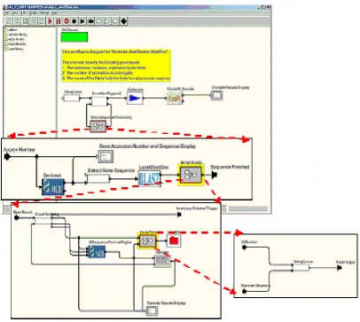
Below is a snapshot of the system GUI as it exists right now. Specifically, it is a snapshot of the
Promoter Identification workflow. We describe the architecture and implementation of the SPA
system in detail in Section 6.1, followed by an evaluation of its Usability.
3
User Interface Design Principles and Evaluation
Graphical user interfaces (GUI) are common today. In fact, they are expected. As already
mentioned, in the context of workflow management systems, it is imperative that the user
interface (graphical or otherwise) be as non-taxing, useful, and intuitive as possible [DFAB97,
Sch86]. Although the underlying functionality of the system is important, it is even more
important that this functionality be presented to the user in a simple and easy-to-use manner, and
at the level appropriate for the end-user’s expertise and domain. The user should not be
overwhelmed by the complexity of the system information technology, but should easily adapt
and make optimum use of it using the interface.
Humans have a great ability to remember and recall graphical concepts and visual cues. Much
better, in fact, than at processing text or using command line interface [DFAB97, SCH86,
Zad99]. Designers of graphical user interfaces have long realized this. A wide array of
techniques is available. They include various graphical query languages, sounds, animations,
virtual reality, etc. Norman’s execution-evaluation model [DFAB97, Nor], and the interaction
framework that extends, is an example of a successful way of analyzing interactions between a
computing system and a human end-user in terms of the difficulty for the user to express what
the user wants and determining whether this has been achieved by the GUI. In [Nor90] Norman
provides guidelines for designing usable systems, and the rationale behind these guidelines. He
explains that an interaction between a human and the system can be divided into two phases --
Evaluation phase in which the user assesses the state of the world, to evaluate the results of his
actions. He recommends designers consider the properties of all the system components as well
as their interactions (especially with humans). He observes that failures of information systems
are attributed to human error rather than to the design, and that designers should design systems
keeping the end-user in mind. He encourages designers to look at bad designs and to avoid the
mistakes that designers of those systems made. A diagram showing Norman’s
Execution-Evaluation model is given below. Although we don’t explicitly follow Norman’s model to guide
our design, we follow User-Centered Design (as the evaluation phase) and Iterative design (as
the feedback phase) as our choices of design, as will be shown in later sections.
Figure 3.1.1: Norman’s Execution-Evaluation Model [Nor]
3.1 Usability
One of the main factors that sets apart one interface from the other is its “usability” [NM94,
Usa04, Nie05]. In very broad terms, usability is what makes a good interface effective, efficient,
enjoyable, and safe. Usability is also a very strong function of the end-user expertise and training
level. Designing for maximum usability is the goal of interactive systems design. However, what
is a very usable for an expert may not be very usable for a beginner. A main issue any designer
of an interactive user interface needs to deal with is measuring of the usability of such a system.
Some of the factors that determine the usability of a system, as described in [DFAB97, Bro03],
are:
• The amount of time it takes the user to learn how to use the system properly,
• The ease with which users can carry out tasks to solve their problems using the system,
• The user’s ability to customize and adapt the system to his way of use, than the other way
around,
• Speed of performance of carrying out such a problem-solving activity using the system,
• The number of errors that occur while performing the activity, and the user’s ability to
avoid errors and recover from them once they occur,
• User’s satisfaction with the system.
Some of the important principles that support usability are:
• Learnability: The ease with which users can use the system efficiently.
• Flexibility: The different ways that the user and system can exchange information.
• Robustness: The level of support provided to the user by the system as he tries to achieve
More details on this are given in [DFAB97]. We implement these principles in the Heuristics that
we propose in Section 4.2.
Some of the principal paradigms for providing usability in WFMS GUIS are “windows”,
metaphors, and direct manipulation.
3.1.1 Windows and the WIMP interface [DFAB97]
The advent and widespread use of Apple Macintosh computers and later windows-based IBM
compatible PC’s, has given rise to one of the more popular design paradigms for interactive
computing, it is called WIMP - for windows, icons, menus and pointers. Windows are areas of
the screen than behave as if they were independent terminals, and usually contain text and
graphics that the user interacts with. Icons are small pictorial representations for closed windows
(or rather windows left in the “background”). Icons essentially make it easier for the user to
switch to different windows using their closed or “minimized” representations. Pointers help the
user point and select things such as icons in a WIMP interface. Menus present choice of
operations or services that the system can perform at a given time. A user usually selects the
desired option using a pointer.
3.1.2 Metaphor [All01]
Metaphors are used to teach new concepts, computer-related concepts being no exception, to
user and computer application. Some of the more popularly known Metaphors are the
Microsoft’s “Desktop” metaphor and the “Paper Clip”. In the SPA system described in the
previous section, Ptolemy implements services as “Actors” and the execution engine as the
“Director”.
However, problems arise once the initial stages of familiarizing one to the concept has gone by,
and the user expects the actual concept to behave very similar to the metaphor being used, often
leading to confusion and dissatisfaction. Microsoft’s friendly Paper Clip was replaced by other
help techniques since both end users and developers never really found the Paper clip very
useful, unlike the actual office paper clip, but extremely animated and intrusive. Some designers
feel the Desktop metaphor, although helpful at the start, is also inadequate up to an extent. For
example, dragging floppy disks to the Recycle Bin may not come across as intuitive way to eject
them. More such problems are discussed in [DFAB97].
3.1.4 Direct Manipulation
Direct Manipulation (DM) allows the user to get rapid feedback and evaluative information for
every executed user action. Thus, for each action that the user performs, the user knows the new
state of the underlying system immediately. The following are the main features of a DM system
as described by Ben Schneiderman [Sch86]:
o Visibility of objects of interest
o Reversibility of all actions, so that users are encouraged to explore without severe
penalties
o Syntactic correctness of all actions, so that every user action is a legal operation
o Replacement of complex command languages with actions to manipulate directly the
visible objects (and, hence, the name direct manipulation)
3.2 Design Approaches
Some of the more popular approaches towards designing user interfaces are:
• User-Centered Design
• Task Analysis
• Rapid Prototyping
These approaches are usually chained into a sequence called the Design Cycle. The Design
Cycle usually starts with obtaining user ideas about the proposed system and initial design,
followed by requirements specification, and design of the prototype. This is usually followed
by evaluation, redesign and reimplementation.
Task Analysis usually describes a wide range of techniques used by ergonomists, designers
and users to describe human-human and human-machine interactions in a system. It is
usually used as an initial technique in the design cycle process to figure out the goals of the
We don’t strictly follow the Design Cycle in our user interface design process because we
feel that the techniques described below (User-Centered Design followed by Iterative
Design) efficiently achieve the goals of the Design Cycle.
3.2.1 User-Centered Design
User-Centered Design (UCD) [VIR01] is the author’s choice of the design approach for a
WFMS. UCD is an approach where user requirements are the determinants in the design of a
usable system. This requires a clear understanding early on in the design of the tasks that the user
wishes to perform. Some guiding principles of UCD are:
• Early focus on, contact with, and understanding of users and their jobs. This ensures that
the users are involved in the design process right from the requirement-gathering phase.
• Integrated Design where all aspects of usability evolve in parallel.
• Early and continual testing of prototypes by users and feedback. Qualitative and
quantitative measurements determine how closely the implemented system’s
specifications match the requirements.
• Iterative Design, where the system is modified based on the testing of the prototype by
the user and his feedback.
The problem with such an approach is that the tasks that the user will perform will be known to
him once he is completely familiar and comfortable with the system. Also, the end-user and
in fine-tuning of the system to cater to a specific group of user’s needs. These and more such
problems with UCD are discussed in [DFAB97].
3.2.1 Iterative Design
Iterative Design [Usa04]is defined by the use of prototypes [DFAB97] which can be defined as
examinable models of the system that simulate some but not all features of the proposed system.
The three main approaches to prototyping are:
• Throw-away: The prototype is used to the point where the exact requirements of the users
are determined iteratively through testing, and finally the proposed system is built from
scratch using the knowledge gained from the prototype.
• Incremental: The overall design for the proposed system is partitioned into independent
and smaller components and the final product is released as a series of products, with
each subsequent release containing one more component.
• Evolutionary: The first version of the prototype is built on iteratively until it finally meets
4 Evaluation Heuristics
Evaluation of user-interfaces has been a topic of research for many years now. However,
most of this work focuses strictly on either single-user systems [DFAB97], mixed-initiative or
intelligent systems [HM93, Keo00, Hor99], or in some cases, systems that belong to the CSCW
(Computer Supported Collaborative Work) category [Gre98, Gru98, McE02, Bak02]. A
Scientific WFMS (SWFMS) as we describe here, is typically a system that a) borrows techniques
from other systems belonging to the above-mentioned categories, and b) is intended for use
primarily by domain experts who “program” it to model and implement their workflows, but
who are not IT experts but their own domain experts (e.g., astrophysicists, bioinformaticians,
etc.).
An SWFMS may not be a single-user system. It functions and manages data in a collaborative
environment. A user may want to use network-based resources (like web-services), and share
workflows (or templates) with other users either synchronously (collaboratively) or
asynchronously. Such a system usually does not qualify as an Artificial Intelligence engine
because it is not completely intelligent, but it may also not be only a CSCW (Computer
Supported Collaborative Work) engine, since the system may not involve synchronous
collaboration in the traditional sense. On the other hand for a collaboration to be possible,
end-users may need to have access to the same set of tools and functions, and may need to exchange
workflows.
from the cognitive and social psychology, such as lab experiments, interviews, focus groups and
customer feedback, or from sociology such as ethnography [DFAB97, SCH86].
For the purposes of this study, we will use a variant of a “heuristic evaluation” [NM94, Nie92]
approach. As defined in [NM94], “Heuristic evaluation is an evaluation technique for user
interfaces that relies on an evaluator’s immediate reactions, intuitions and predictions, that fall
under a set of Design Principles and Usability Attributes”. For most part, such an evaluation, we
hope, will be formative, i.e. help towards the iterative development of a system (or a prototype)
of this kind.
Evaluations can be of two kinds – Analytical or Empirical. While Analytical evaluations focus
on how the system would probably function in a given scenario, Empirical evaluations focus on
creating a prototype or the system itself and having users use it and provide feedback. Heuristic
Evaluation is one of the better Empirical evaluation processes. It has the following advantages:
• It is easy and intuitive to perform,
• It is a good method for finding both major and minor problems in system,
• It is suitable for use in the early development process, and hence is low cost since the
problems discovered are much easier to fix than if found later,
• No advance planning is required since evaluators can evaluate the system as a team,
• Since each problem discovered is in reference to an already established usability problem
4.1 Heuristic Evaluation Process
While usability-engineering methods can contribute substantially to the resulting interface, many
developers find usability methods intimidating, expensive, and too difficult and time consuming
to apply. Heuristic evaluation can help in such cases. It is one of the principal discount
usability-engineering methods, and yet can give quite good results [NM94]. It employs methods that are
cheap, fast, and easy to use [NM94, Nie92].
Heuristic evaluation can be used as part of usability engineering to finding usability problems in
a user interface design. Such an evaluation is usually an integral part of an iterative design
process. It involves having a small set of evaluators, an expert group, examine the interface and
judge its compliance with recognized usability principles. It is a variant of the classical Delphi
Method [Delphi].
Heuristic evaluation involves more than one evaluator. Each evaluator inspects the interface
alone to find usability problems. After all the evaluations have been completed, the evaluators
communicate with each other and aggregate their findings. Typically, a heuristic evaluation
session for an individual evaluator lasts one or two hours, though longer evaluation sessions are
not uncommon for more complex systems.
During the evaluation session, the evaluator goes through the interface several times and inspects
the various elements of the user interface and compares them with a list of recognized usability
possibly be relevant for any specific element in the given context. In such cases, as will be
shown later, it is possible to develop category or domain specific heuristics that apply to a
specific class of products as a supplement to the general heuristics.
In most cases, it is upto the evaluators to decide as to how to proceed with evaluating a user
interface. A common practice is on where the evaluators go through the interface at least twice
where the first pass would be intended to get a feel for the flow of the interaction and the general
scope of the system, and the second pass allows the evaluator to focus on specific interface
elements and evaluate them.
Although it is recommended that the number of evaluators be more than one for purposes of
Heuristic Evaluation, it is not uncommon for Heuristic Evaluation to be carried out by a single
expert for smaller projects, or projects where the end user has been providing constant feedback
during each design phase. In our case, the author of this study is responsible for the Heuristic
Evaluation for the tools mentioned in the Section 6. However, evaluations of these tools by other
authors, developers, and end users were taken into consideration while creating the Usability
Heuristics and conducting the Heuristic Evaluation itself. For this reason, we refrain from
assigning severity ratings to the usability problems discovered, and use a more flexible way to
outline the severity of the problem, as will be shown in Table 6.6.1.
4.2 Usability Heuristics and Metrics
Since the start of this project about 2 years ago, we have identified the following to be the basic
define the desirable properties of a usable interface, ensure that the tool is truly intuitive and
user-friendly, and alternatively can be used as metrics based on which an evaluator (or
alternatively an interface designer) may assess an existing system. Some of the metrics have
been borrowed from the HCI discipline [DFAB97], UI Patterns [Tal98], or Workflow Patterns
[WP04, ABHK00], while others have been discovered in the requirements gathering process.
While these features are necessary, they are not sufficient. Managers and end-users of the system
would ideally compile a complete set of heuristics for such an evaluation during initial design
phases with the help of HCI and usability experts [NM94, Nie92, Nie05]. Such a specification of
heuristic metrics usually changes through various iterations of the design phases as more
feedback is received and specific details of the design are deduced.
Below we present a set of such heuristic metrics for a Scientific WFMS. These are based on
heuristics defined by Nielsen [DFAB97, Nm942], and were adapted to fit our description of such
a system.
4.2.1 Construction and Execution of workflows
A Scientific WFMS should allow a scientist to chain different tasks or services together to form
an analytical flow. The scientist should be able to specify the sequence of steps (some of which
may be parallel) that the scientist wants to execute, inputs and outputs, and information about
how output data of the executing task(s) maps to the input of the next-in-line task. In general, a
scientist should be able to specify equivalent of a full general activity graph [Dav91]. For
example, steps may be synchronous or asynchronous, interactive, collaborative, and tasks may be
able to specify or modify task specific parameters that will make the task behave one way or the
other, e.g. specific method to be used within the given web-service, name for the task, etc. The
user should be able to “execute” the workflow, and he should be able to stop or pause it
temporarily if needed, and to interact with it. He should be allowed to “background” this control
flow and create and/or execute a new workflow separately. Thus the end user should be able to
“orchestrate” the workflow the way the user wants. A workflow “recording” should be storable
and exchangeable in a standard way.
4.2.2 Match between system and real world [DFAB97, NM94]
The system should “speak” the user’s language, with terminology, phrases and concepts familiar
to the user, rather than be system-oriented or information technology oriented. It should follow
real-world conventions, making information appear in natural and logical order. A Metaphor
[Tal98] may be employed, to help the user draw natural comparisons to the system being used
and the domain world in which the user operates.
4.2.3 Ease of Use
Every system designed for use by actual end-users (as against systems that “talk” to other
systems) needs to be easy to use for the intended end-user. It has to be sensitive to the end-user
information technology expertise level and domain expertise level. The two may be vastly
different. This especially becomes a necessity in cases where a complex system will be used by
an end-user who does not want to deal with all the internal details of the system. In our case, the
scientist does not need to, and very often does not want to, know the information technology
Thus, the system must have an “appliance-like” interface that makes it easy to use in the
end-user domain, but hides all the underlying information technology details of the system that the
end-user does not need to know or adjust.
Ease of use also implies an uncomplicated way of installing and uninstalling the system. A user
should not have to worry about how to install the software package by putting different
components together and the package should have self-installation capabilities.
4.2.4 Flexibility and efficiency of use
The user should have full control of the system (although some steps and procedures may be
“automated”), and have the freedom to modify the current state of execution as and when he
pleases. A complex system of this kind should at all times support undo and redo functionality.
Also, Accelerators [DFAB97] should be employed. Accelerators allow users to tailor frequent
actions by employing shortcut keys for such actions. These would usually not be used by the
novice user, but may often speed up the interaction for the expert user to such an extent that the
system can cater to both inexperienced and experienced users.
4.2.5 Consistency and Standards
The user interface of a system as complex as described here should have a consistent
look-and-feel, and if it employs any metaphors, they should be implemented consistently as well. Users
should not have to wonder whether different words, situations and actions mean the same thing
It is important that standards be implemented wherever applicable. In case of scientific
workflows, not only should the user interface comply with industry standards of design and
evaluation as discussed earlier, but also the underlying layers should implement a standard
language for representation of data. XML has proven to be an efficient standard for this purpose,
one that is widely accepted by the industry. A lot of industry standards have been recommended
by the WfMC [WfMC04], and a detailed comparison of these standards is given in [ABHK00,
WP04].
4.2.6 Recognition rather than recall
All options, objects and possible actions should always be made visible. The user should not
have to remember information from one part of the dialog to another. Instructions for use of the
system should be visible or easily retrievable whenever appropriate.
Also, automation [DFAB97] to the extent that it adds value should be implemented. It is
important to provide automated services that provide genuine value over solutions attainable
with direct manipulation.
4.2.7 Aesthetic and minimalistic design
Dialogs should not contain information that is irrelevant or rarely needed. Every extra unit of
information in a dialog competes with the relevant units of information and diminishes their
The widgets and objects used for interaction with the end user should be minimal, and under no
circumstances should these distract or annoy the user in any way.
4.2.8 Employing dialog to resolve key uncertainties
If a system is uncertain about a user’s intentions, it should be able to engage in an efficient
dialog with the user. However, care should be taken that such a dialog does not unnecessarily
bother or completely annoy the user.
4.2.9 Interaction with the end-user and Visibility of System status
The system should always keep users informed about what is going on, through appropriate
feedback within reasonable time.
The user interface should have data-tracking display abilities which allow an end-user to actively
monitor the execution of the workflow at all times. He should be able to see which service in the
workflow is currently executing graphically (change of color, etc.) and via text messages. A user
should always be informed when a given service finishes execution, so the user can inspect the
output results and make modifications to the workflow if need be.
The user should be provided with status information at all times as to how far along a particular
service is in execution and approximately how much longer it will take for it to execute
complete capability of inspecting the execution of a workflow and its outcome, and go back and
change the flow of control in the workflow if needed.
4.2.10 Allowing efficient direct invocation and termination
A system that is exploratory in nature, and is operating under uncertainty will sometimes make
poor decisions about invoking, or not invoking an automated service. Providing efficient means
by which users can directly invoke or terminate the automated service can enhance the value of
agents providing automated services.
4.2.11 Interaction with a Central Repository
A central repository should be made available to the user, from which he can choose predefined
tasks or services to chain together to form a workflow. A well-known web-service registry
service is IBM’s UDDI, but a local (or central) database or a flat file system can be used easily.
What is important is that these tasks/services are pre-defined and available to the users for use at
all times (preferably in an intuitive drag-and-drop manner), and can be modified according to the
end-user’s preference.
Also, the end-user should be able to publish services to this same repository. In collaborative
environments, the tool will be used by various domain-specialists. It is always helpful if a user
creates a task and registers it on the central repository, so another user (or the very same user)
It is important that there be descriptions associated with such tasks in the repository so the end
user does not spend time testing a service and figuring out its functionality. An architecture of
this kind, as discussed in Section 2.3, enables an efficient way to find and use services. This also
enables fault-tolerance, since if a given service implemented in a workflow fails or shuts down,
the user can choose an alternative service that implements the same functionality. It is important
that the service discovery module of the registry have an interface that allows the user to describe
the functionality desired and use it in his workflow in an intuitive manner.
4.2.12 Data-Mapping
A good WFMS should provide the user with data-transformation capabilities (preferably
graphical entities) that allow him to map and transform data as it passes from one service to the
next. However, more basic transformations (like integers to strings) should be taken care of by
the system itself, only the more workflow-specific (or domain-specific) ones should be left to the
end-user.
4.2.13 Decision-based execution
In many scientific workflows, certain data flows are executed repeatedly, whereas others are
executed based on the logical outcome of a given condition preceding this data flow. The WFMS
to be a way to translate the user’s logic into the underlying workflow language. Specifically, the
following kind of nodes should be allowed and processed:
• Conditional Branching: The user should be able to specify conditions that will be
evaluated and based on the outcome the workflow will take one route or the other.
Support for logical operators AND, OR, XOR, NOT, etc. is important.
• (Conditional) Looping: The user should be able to execute parts of workflows (subflows)
within for and while loops. It should be easy for him to specify iteration criteria and
parameters.
• Splits and Joins: The user should be able to “split” the workflow by having services in the
flow execute in parallel if the output of one does not depend on the output of the other.
He should also be able to “merge” or join results obtained from such execution and use it
as an input to the following service.
4.2.14 Visualization of output data
It is very important that the output from individual services of a workflow, and the workflow as a
whole, be in a format desired by the end user of the workflow. Also, the end-user should be
allowed to view the results of the workflow in various different formats permissible given the
nature of output (as opposed one specific kind of output). For example, an end-user should be
able to view his numeric output as points in space, tabular format, histogram, etc. If the WFMS
is domain-specific, such domain-specific output formats should be possible (e.g. for a
4.2.15 Reusability of Workflows
The user should be able to save a workflow along with its status, and should be able to retrieve it
at a later time to re-run or re-inspect it. He should have a choice of saving workflow information
locally, or on the central repository such that other users can use it. It should also be possible for
the user to store the outputs of various services and the entire workflow.
4.2.16 Verification, Validation and Fault-Tolerance
Each of Verification, Validation and Fault-Tolerance are features that should be provided by the
underlying system that supports the WFMS. However, there always should be user-friendly ways
to convey this information to the user correctly, and not confuse him. Error and system messages
should have priorities, and should be relayed to the user with appropriate suggestions. If a user
commits a mistake while creating the workflow, he should be corrected and advised on how to
correct it. If a service fails, the user should be given a choice of alternate services that he can use.
Thus, recognizing, diagnosing and recovering from errors should not be overwhelming for the
user. The system should also implement features that prevent errors on the user’s part.
4.2.17 Minimizing the cost of poor guesses about action and timing
Recovering from errors should be fairly easy to achieve.
4.2.18 Help and Documentation
Even though it is better if the system can be used without documentation, it is good to provide
help and documentation. Any such information should be easy to search, focused on the user’s
task, and list concrete steps to be carried out, and not be too large.
4.2.19 Security and Protection
Security is a concern with WFMS’s used in collaborative environments, but it is usually
managed by underlying layers. However, care should be taken on the user-interface and in case
of extremely complex security policies so that security features do not baffle the user. It has been
shown that scientists prefer easy-to-use systems with simple security features, than systems with
more complex security features.
The system should implement features that allow the user to backup their workflows in a simple
manner. Recovering data and partly complete workflows from failure should be easy to achieve
4.2.20 Web-based GUI
It is important that Scientific WFMS’s make their visual components available via the browser
for users who may not want to install and run the system locally. Although systems such as
scientific workflow systems are intended to be client-centric and be available to the end-users as
software suites by themselves, the user should have an option of running the workflow using a
browser, although it may have limited capabilities for security reasons. The browser interface
may be a Java Applet, however, care should be taken about the visual interface if the user will
have the capability of accessing local files and data via the applet. An intermediate servlet or
Struts framework may have to be used to access such local data.
4.2.21 Interoperability
In collaborative environments, end users typically use a variety of tools and legacy systems to
form various workflows. Although we describe a service-based architecture here, the scientist
may use a third-party tool for other purposes such as visualization, reporting, etc. Then, the
visual interface of the given WFMS (along with supporting layers) should have the functionality
of letting the user conveniently hook into outside systems. One needs to make sure that the user
is offered a consistent look and feel when accessing other systems to avoid confusing him, which
is not a trivial task.
This is one of the more difficult and challenging features to achieve in a WFMS, and has been a
Apart from the above-mentioned features, each WFMS created for a specific domain will have
different requirements for its visual component. At the very least, the user-interface should
5 The Pilot system
We explained in the previous sections our approach of using iterative design and a prototype in
our user-interface design cycle. The pilot system, created during the inception of this project was
used as a prototype, based on requirements and feedback received from our pilot user, Dr.
Matthew Coleman. A design process of this kind helps understand the requirements and
architecture better, since both the developers and end users have a better understanding of the
functionality desired after several iterations of design and development. It also helped us
evaluate, select and formulate our interface evaluation criteria.
As must be obvious by now, the most intuitive way to describe a workflow is in the form of a
directed acyclic graph (DAG) [DADS05, Dav91], where the vertices (nodes) represent specific
tasks or services and the edges represent flow of control and data. However, a more complete
general activity network (GAN) diagram could be used [Elm64, Elm66, Elm95]. The
user-interface of a WFMS should allow the end-user to create an “executable” graph consisting of
services and information about the sequence of execution and the data and information passed
between the nodes. In this section we introduce our prototype system, SDMSWE [Cha02,
LAGM03] that was based on the DAG view of the process.
5.1 The SDMSDWE System
SDMSWE stands for SDM Scientific Workflow Environment. SDMSWE has a user interface
that closely manifests a user interface designer’s idealistic specification of a scientific WFMS.
architecture. Our earliest prototypes on paper were designed keeping in mind ease of use as a
primary goal, hence SDMSWE has a very simple yet effective design. However, it has limited
capabilities when it comes to handling heterogeneous and highly structured data, and thus it was
replaced by a more robust architecture.
The SDMSWE workflow tool lets the user define, construct and execute a sequence of data and
analysis services the user wants to invoke. It creates a Web Service based environment for
executing and monitoring workflows.
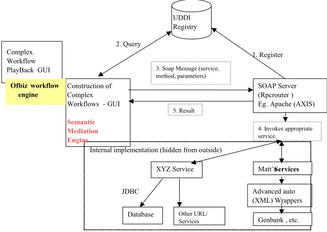
Below is an architecture diagram of the implemented system.
Complex. Workflow PlayBack GUI
Ofbiz wo flow rk engine
4. Invokes appropriate service.
, etc. Genbank Matt’s Services
Advanced auto (XML) Wrappers Other URL/ Services JDBC Database XYZ Service 2. Query 1. Register 5. Result 3. Soap Message (service, method, parameters)
SOAP Server (Rpcrouter Eg
) . Apache (AXIS) Construction of
Complex Workflows -GUI
UDDI Registry
Internal implementation (hidden from outside)
Semantic Mediation Engine
The workflow editor allows the user to create exploratory workflows using various tasks
(web-services). These web-services are registered on the UDDI [UDDI04], and also on a backend
PostGRE database associated with OfBiz [OfBiz03] workflow engine. On execution, the SOAP
server (here, Apache Axis) is called which invokes each service in the sequence specified on the
user interface. The service definitions are stored in a database associated with the Axis server.
This system has the following characteristics:
• Easy to use interface for creating, editing, saving and monitoring linear and non-linear
workflows that involve multiple services and data resources, possibly heterogeneous in
nature.
• The workflow consists of task nodes that are connected into a directed graph. Each task
represents a unit of work to be done which may invoke a (web) service on the remote
machine, or a service over the web, or even a local program. It may also deliver
information from a web page.
• The workflow editor can dynamically locate services registered with the UDDI and
extract service details. The workflow editor allows the user to select Matt’s (PIW)
[ABB+03] services from a service menu and draw them as tasks. In essence, this
eliminates the need on the users part to enter parameters for a task. The parameters are
automatically assigned to the task. All the user needs to do is select the service and click
on the workflow designer to see the task drawn.
• The services (service details) are extracted from the workflow engine database. In our
![Figure 3.1.1: Norman’s Execution-Evaluation Model [Nor]](https://thumb-us.123doks.com/thumbv2/123dok_us/1425667.1175077/28.612.143.469.345.622/figure-norman-s-execution-evaluation-model-nor.webp)
![Figure 6.2.1: The SCIRun Window Frame [SCIRun04]](https://thumb-us.123doks.com/thumbv2/123dok_us/1425667.1175077/72.612.207.404.225.442/figure-the-scirun-window-frame-scirun.webp)
![Figure 6.2.2: SCIRun Sample Workflow [SCIRun04]](https://thumb-us.123doks.com/thumbv2/123dok_us/1425667.1175077/73.612.167.445.71.406/figure-scirun-sample-workflow-scirun.webp)
![Figure 6.2.3: Anatomy of a SCIRun Module [SCIRun04]](https://thumb-us.123doks.com/thumbv2/123dok_us/1425667.1175077/74.612.208.407.73.224/figure-anatomy-of-scirun-module-scirun.webp)
