Survey Paper on Multiplier-less 1-D Discrete
Wavelet Transform based on ROM
Ankit Pathak, Prof Bharti Chourasia
M Tech. Scholar, Dept. of Electronics and Communication, SCOPE College of Engineering, Bhopal, India Head of Dept, Dept. of Electronics and Communication, SCOPE College of Engineering, Bhopal, India
ABSTRACT: Conventional distributed arithmetic (DA) is popular in field programmable gate array (FPGA) design, and it features on-chip ROM to achieve high speed and regularity. In this paper, we describe high speed area efficient 1-D discrete wavelet transform (DWT) using 9/7 filter based distributed arithmetic (DA) Technique. Being area efficient architecture free of ROM, multiplication, and subtraction, DA can also expose the redundancy existing in the adder array consisting of entries of 0 and 1. This architecture supports any size of image pixel value and any level of decomposition. The parallel structure has 100% hardware utilization efficiency.
KEYWORDS: - 1-D Discrete Wavelet Transform (DWT), DA, Low Pass Filter, High Pass Filter, Xilinx Simulation.
I. INTRODUCTION
The well-known image coding standards, namely, MPEG-4 and JPEG2000 have adopted 1-D DWT as the transform coder due to its remarkable advantages over the other transforms. For lossy and lossless compression, Daubechies 9/7 orthogonal filter is used as the default wavelet filter in JPEG 2000. Efficient implementation of 1-D DWT using 9/7 filters in resource-constrained hand-held devices with capability for real-time processing of the computation-intensive multimedia applications is, therefore, a necessary challenge. Multiplier-less hardware implementation approach provides a kind of solution to this problem due to its scope for lower hardware-complexity and higher throughput of computation.
Several parallel and pipeline systems that meet the computational requirements of the discrete wavelet transform have been proposed. Some of them need multiprocessor to implement it and the system is complex, time consuming, and costly [1]. The Field programmable gate array (FPGA) provides us a new way to digital signal processing [2].
Several designs have been proposed for the multiplier, multiplier-less implementation of 1-D DWT based on the principle of multiplier based design (MBD) distributed arithmetic (DA) canonic signed digit (CSD), [1]–[3]. The structure of distributes the bits of the fixed coefficients instead of the bits of input samples. Consequently, the adder-complexity of the structure of depends on the DA-matrix of the fixed coefficients [2].
Canonic signed digit (CSD) are popular for representing a number with fewest number of non-zero digit. The CSD representation of a number contains the minimum possible number of nonzero bits, thus the name canonic. The CSD representation of a number is unique and CSD numbers cover the range (-4/3, 4/3), out of which the value in the range {-1, 1} are of greatest interest.
Martina et al [5] have approximated the 9/7 filter coefficients and performance of a hardware implementation of the 9/7 filter bank depends on the accuracy of coefficients representation. By that approach, they have significantly reduced the adder-complexity of the 9/7 DWT. Gourav et al [7] have suggested an LUT-less DA-based design for the implementation of 1-D DWT. They have eliminated the ROM cells required by the DA-based structures at the cost of additional adders and multiplexors.
Some of them need Rom to implement it and the system is complex, time consuming, and costly [4] The adder-complexity of this structure is significantly higher than the other multiplier-less structures. In this paper, we have proposed an efficient scheme to derive DA-based bit-parallel structures, for low-hardware and high-speed computation DWT using 9/7 filters [4].
II. DISTRIBUTED ARITHMETRIC (DA)
Let us consider the following sum of products [4]:
k L k k Y X
R
1
(1)
Where
X
kare fixed coefficients and theyY
k are the input data words. Equation (1) can be expressed in the form of amatrix product as:
L L Y Y Y X X X R . ... 2 1 2 1 (2)Both
X
kandY
kare in two’s complement format. The two’s complement representation ofX
k may be expressed as
12
2
M N i i i k M M kk
X
X
X
(3)Where
X
ki
0 or 1, andi
N, N+1… M andX
kMis the sign bit andX
kNis the least significant bit (LSB). Equation (3) can be expressed in matrix form as:
M k N k N k M N N kX
X
X
X
.
2
...
2
2
1 1 (4)Similarly
Y
kcan be represented in two’s complemented format as:
12
2
X W i i i k X X kk
Y
Y
Y
(5)Where
Y
ki
0 or 1, andi
W, W+1, …,X andY
kMis the sign bit andY
kNis the least significant bit (LSB).Now on combining equations (1) and (3), we get-
1)
2
.
(
)
2
.
(
M N i i i M MR
R
R
(6)Where
L k k i k iY
X
R
1III. PROPOSEDARCHITECTURE
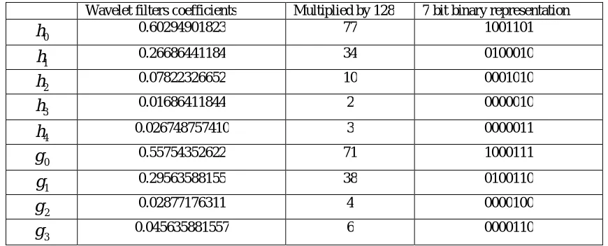
In this paper, we have proposed a high speed area efficient multiplier-less 1-D 9/7 wavelet filters based DA technique. 9/7 wavelet filters coefficient i.e. 9 low-pass and 7 high-pass wavelet filters coefficient are given in table1. We multiply the filter coefficients by 128 for simplification. The mathematical calculation for 1-D high pass filter output is explained by an example.
Table 1: Show high-pass and low-pass wavelet filters coefficient.
Wavelet filters coefficients Multiplied by 128 7 bit binary representation
0
h
0.60294901823 77 10011011
h
0.26686441184 34 01000102
h
0.07822326652 10 00010103
h
0.01686411844 2 00000104
h
0.026748757410 3 00000110
g
0.55754352622 71 10001111
g
0.29563588155 38 01001102
g
0.02877176311 4 00001003
g
0.045635881557 6 0000110Where
h
0,h
1,h
2,h
3,h
4are the Low pass filter coefficients andg
0,g
1,g
2,g
3are the High pass filter coefficients.If we take the high pass coefficients
g
0,g
1,g
2andg
3 multiply byr
1,r
2,r
3andr
4then we get the High passoutput
Y
Hof the 9/7 filter as [6]:
4 3 2 1
3 2 1 0
r
r
r
r
g
g
g
g
Y
H (7)Where
r
1
Y
(
n
)
Y
(
n
6
)
r
2
Y
(
n
1
)
Y
(
n
5
)
r
3
Y
(
n
2
)
Y
(
n
4
)
r
4
Y
(
n
3
)
Let
r
1=1,r
2=2,r
3=3,r
4=4 then
183
4
3
2
1
6
4
38
71
H
Now if we implement this with DA then
4 3 2 1
0000110 0000100
0100110 1000111
r r r r YH
(9)
Now we can make the DA matrix by the filter coefficients as
0 0 0 0 0 1 1 0
0 0 0 0
0 0 0 0
1 1 1 1
1 0 1 1
0 0 0 1
k
B
1 2 4 3 2 1 4 2 1 1 4 3 2 1 0 0 0 0 0 0 0 1 1 0 0 0 0 0 0 0 0 0 1 1 1 1 1 0 1 1 0 0 0 1 r r r r r r r r r r r r r r
YH (11)
In Figure 2, apply DA techniques step-1 all the input converts’ binary number, Step-2 all the binary input applied to a adder array so,
0001
1
P
,P
2
0111
1010
3
P
,P
4
0000
0000
5
P
,P
6
0010
0001
7
P
The entire adder array input applied to MUX so, the entire adder array input
m
(
1
)
MUX (1) = 0001 =Yp (0)MUX (1) add MUX (2) = YP (1)
= 00001 = 01110 + 01111
Output of the YP (1) again right shift 1-bit and adds MUX (3) so
= 001111 = 101000
+ 110111
YP (1) + MUX (3) = YP (2)
Output of the YP (2) again right shift 1-bit and adds MUX (6) so
= 000110111 = 001000000 + 001110111
YP (2) + MUX (6) = YP (3)
Output of the YP (3) again right shift 1-bit and adds MUX (7)
so
= 001110111 = 001000000 + 010110111 YP (3) + MUX (6) = YP (4)
Total output YP (4) = 010110111 = 183
IV. CONCLUSION
component and free of ROM (free memory), multiplication, and subtraction. For the adder array, a systematic approach is introduced to remove the potential redundancy so that minimum additions are necessary. DA is an accuracy preserving scheme and capable of maintaining a satisfactory performance even at low DA precision.
REFERENCES
[1] S.G. Mallat, “A Theory for Multiresolution Signal Decomposition: The Wavelet Representation”, IEEE Trans. on Pattern Analysis on Machine Intelligence, 110. July1989, pp. 674-693.
[2] M. Alam, C. A. Rahman, and G. Jullian, ”Efficient distributed arithmetic based DWT architectures for multimedia applications,” in Proc. IEEE Workshop on SoC for real-time applications, pp. 333 336, 2003.
[3] X. Cao, Q. Xie, C. Peng, Q. Wang and D. Yu, ”An efficient VLSI implementation of distributed architecture for DWT,” in Proc. IEEE Workshop on Multimedia and Signal Process., pp. 364-367, 2006.
[4] Archana Chidanandan and Magdy Bayoumi, “AREA-EFFICIENT NEDA ARCHITECTURE FOR THE 1-D DCT/IDCT,” ICASSP 2006. [5] M. Martina, and G. Masera, ”Low-complexity, efficient 9/7 wavelet filters VLSI implementation,” IEEE Trans. on Circuits and Syst. II,
ExpressBrief vol. 53, no. 11, pp. 1289-1293, Nov. 2006.
[6] M. Martina, and G. Masera, ”Multiplierless, folded 9/7-5/3 wavelet VLSI architecture,” IEEE Trans. on Circuits andsyst. II, Express Brief vol. 54, no. 9, pp. 770-774, Sep. 2007.
[7] Gaurav Tewari, Santu Sardar, K. A. Babu, ”High-Speed & Memory Efficient 2-D DWT on Xilinx Spartan3A DSP using scalable Polyphase Structure with DA for JPEG2000 Standard,” 978-1-4244-8679-3/11/$26.00 ©2011 IEEE.
[8] B. K. Mohanty and P. K. Meher, “Memory Efficient Modular VLSI Architecture for Highthroughput and Low-Latency Implementation of Multilevel Lifting 2-D DWT”, IEEE TRANSACTIONS ON SIGNAL PROCESSING, VOL. 59, NO. 5, MAY 2011.
[9] B. K. Mohanty and P. K. Meher, “Memory-Efficient High-Speed Convolution-based Generic Structure for Multilevel 2-D DWT”, IEEE TRANSACTIONS ON CIRCUITS SYSTEMS FOR VIDEO TECHNOLOGY.