R E S E A R C H
Open Access
Full-duplex amplify-and-forward relays
with optimized transmission power under
imperfect transceiver electronics
Gustavo J. González
1*, Fernando H. Gregorio
1, Juan E. Cousseau
1, Taneli Riihonen
2and Risto Wichman
2Abstract
In-band full-duplex (FD) relays are useful for extending coverage areas and increasing overall throughput in wireless networks. The main technical difficulty hindering their implementation and use is their inherent self-interference (SI), generated due to simultaneous in-band reception and forwarding. Efficient SI mitigation is a practical necessity, and the imperfections in transceiver electronics, from which power amplifier (PA) non-linearity is one of the most serious phenomena, have to be taken into account in order to not limit the performance of such techniques. The magnitude of the distortion introduced by the PA depends on the relay input back-off (IBO) whose optimization for alleviating the effect of PA non-linearity is the main research objective in this paper. In particular, although plain signal-to-noise ratio (SNR) at the destination obviously increases when the IBO decreases, increased transmit power also strengthens the non-linear distortion leading to decreasing overall signal-to-interference-plus-noise ratio (SINR). We develop expressions for bounding the optimal IBO setting that maximizes the SINR at the destination, considering all relevant hardware impairments and SI cancellation with I/Q imbalance compensation. We provide closed-form solutions for the soft-limiter PA model and numerical results for more general PA models. Finally, the derived IBO bounds are compared with the numerical maximization of the SINR and the minimization of the bit-error rate (BER) to demonstrate that the theoretical bound settings provide good approximations to the optimal one.
Keywords: In-band full-duplex wireless communication, Non-regenerative relays, Optimization, Self-interference cancellation, Transceiver hardware impairments
1 Introduction
Advances in electronics, integration techniques, and signal processing are about to enable real full-duplex (FD) operation without frequency division in wireless transceivers, which is one of the most sought objectives since the invention of radio transmissions [1]. In con-trast to conventional half-duplex (HD) transceivers, a FD transceiver is able to transmit and receive simultaneously in the same frequency band. Besides doubling the theo-retical spectral efficiency, this may open up a wide range of new applications from cognitive radio spectral sensing [2] to more efficient medium access protocols [3–5]. This
*Correspondence: [email protected]
1CONICET-Department of Electrical and Computer Engineering, Universidad Nacional del Sur, Av. Alem 1253, Bahía Blanca, Argentina
Full list of author information is available at the end of the article
paper concerns specifically the deployment of FD amplify-and-forward (AF) relays, or repeaters, that can satisfy the demand of high data throughput and extend coverage area in modern networks, without increasing frequency reuse [6, 7].
The main impediment for FD implementation is the self-interference (SI) caused by the coupling of the transmitted signal to the receiver chain. In compact transceivers, the interference level is usually high com-pared to the signal of interest [8], depending on the trans-mitted signal power, the isolation between transmitter and receiver antennas, and the surrounding environmental reflectors. Self-interference is mitigated by a combina-tion of passive and active antenna cancellacombina-tion [9, 10] and RF cancelers [11, 12], both in the analog domain; and a digital cancellation [13–16]. Antenna cancellation tech-niques aim to reduce the physical coupling between the transmitter and the receiver antennas. Passive techniques
optimize the distance and the orientation of the anten-nas, and include absorbers to lower the interference. On the other hand, active techniques are based on the use of multiple antennas and beamforming. After that, RF can-cellation subtracts a contribution of the transmitted signal at the receiver for further SI mitigation. Analog stages reduce the SI in order to relax the specifications of the low-noise amplifier and to avoid the desired signal to be drowned by the analog-to-digital converter (ADC) quanti-zation noise [17]. After that, the digital canceler mitigates the residual interference.
Many cancelers have been proposed in the literature [1, 9, 15, 16], but their performance is greatly affected by hardware imperfections. In particular, the effect of power amplifier (PA) non-linearity for FD transceivers is consid-ered in [3, 18–21], while the HD relay case is treated in [22]. A widely linear I/Q imbalance and SI cancellation concept is proposed in [14] for a generic FD transceiver and in [23] for an AF FD relay. Additionally, the outage probability of a FD decode-and-forward relay link with I/Q imbalance is derived [24]. On the other hand, the effect of ADC quantization noise is analyzed in [17]. The most harmful RF nonideality is the PA non-linearity that closely depends on the PA input back off (IBO) [3]. The higher the IBO the lower the PA non-linear effect but also the lower the PA efficiency.
Additionally, the IBO (or equivalently the PA trans-mit power) sets an interesting trade off in the signal-to-interference-plus-noise ratio (SINR) of the two-hop relay link.If the IBO decreases, the signal-to-noise ratio (SNR) at the destination increases, but at the same time this also increases PA non-linear interference level and the SI, reducing the SINR at the relay input.As a consequence, an optimal IBO that maximizes the SINR at destination can be found.
In this work, we derive expressions that bound the opti-mal IBO that maximizes the SINR at the destination, considering RF impairments. First, we find the expres-sion of the SINR at the destination considering the SI and I/Q imbalance canceler proposed in [23]. Then, we derive lower and upper bounds for the optimal IBO that max-imizes the SINR. The SINR maximization can be seen as a suboptimal minimization of the bit error rate (BER). The BER minimization problem was previously solved numerically in [23]. Additionally, we provide closed-form expressions for the bounds considering the soft limiter (SL) PA model, and present numerical solutions for more general PA models. The analysis presented in this article is valid no matter the chosen PA model or its non-linear compensation. Finally, using simulations, we compare the obtained theoretical bounds with the numerical maxi-mization of the SINR and the minimaxi-mization of the BER to show that our derivations provide a good approximation of the optimal IBO.
The rest of the paper is organized as follows: In Section 2, we introduce the system model and the hard-ware imperfections. We find the optimal IBO that maxi-mizes the SINR of the relay link in Section 3. In Section 4, we compare the proposed bounds with the numerical maximization of the SINR and the minimization of the BER, for different conditions. Finally, we conclude the paper in Section 5.
2 Signal model for the two-hop relay link
We consider a two-hop relaying scheme where the source (S) reaches the destination (D) through a relay (R), without a direct link between the source and the destination. We focus on the downlink, i.e., the link base station—relay—mobile device. The relay operates in the full-duplex mode and implements the amplify-and-forward protocol while signals are modulated with orthogonal frequency-division multiplexing (OFDM). We assume perfect time and frequency synchronization and that the cyclic prefix (CP) is longer than channel impulse responses.
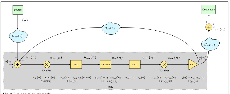
A simplified digital baseband model of an AF relay is illustrated in Fig. 1, where x(n) is the OFDM signal transmitted by the source, η(n) is white Gaussian ther-mal noise at the relay input with varianceση2,ur(n)is the received signal distorted by the coupling feedback path whileudc(n)is the corresponding baseband signal,uad(n) is the digital signal after the ADC,uw(n)is the compen-sated signal, uda(n) is the signal after digital-to-analog conversion (DAC),uuc(n)is the RF signal,y(n)is the relay output signal after high-power amplification, and ηd(n)
is white Gaussian thermal noise at the destination with varianceσd2.
The signal propagates through the two-hop link formed by the source–relay channelHsr(z)=hsr,0+hsr,1z−1+. . .+
hsr,Lsrz−Lsr and the relay-destination channel Hrd(z) =
hrd,0+hrd,1z−1+. . .+hrd,Lrdz−
Lrd, of respective lengths
Fig. 1Two-hop relay link model
residual baseband SI channel already takes into account these cancellation effects.
The proposed widely linear I/Q compensation and SI cancellation scheme consists of a pair of filters:W1(z)and
W2(z).
We assume that electronics in the source and destina-tion transceivers are ideal, in order to focus on the effects of relay disturbances on the system performance. In the following, we present imperfection models of the down-and up-conversion mixers, the ADC, the DAC, down-and the PA of the relay. We model all the imperfections in the transceiver front-ends using their digital baseband nor-malized equivalents. The amplification effects and the antenna and RF attenuation are absorbed by the SNRs at the relay and destination inputs and the channel models.
The effect of the down- and up-conversion mixers over the baseband digital signal can be modeled as
udc(n) = κrur(n)+χru∗r(n) (1)
uuc(n) = κtuda(n)+χtu∗da(n) (2)
whereκr=(1+αre−jθr)/2,χr =(1−αrejθr)/2,κt=(1+
αte−jθt)/2,χt = (1−αtejθt)/2; andαr,αt,θr, andθt are respectively the amplitude and phase mismatches of the receiver and transmitter mixers [25].
We recognize that the ADC effects can be modeled by a scaling factorκadand an additive quantization noise term [17]. The variance ofηad(n)can be calculated as [3]
σ2 ad=E
|udc|2
10−(6.02b+4.76−P(udc))/10 (3) where E{·}is the expectation operator,bis the bit resolu-tion of the ADC, andP(udc)is the peak-to-average power ratio of the input signal udc(n) expressed in decibels. Additionally, we include a processing delay ofdsamples in the ADC, i.e.,uad(n) = κad udc(n−d)+ηad(n). The
DAC is regarded ideal, i.e.,uda(n) = uw(n). Considering a single local oscillator at the relay and a short processing delay, as it is the case of AF relays, the phase noise effect can be neglected [26].
If the number of subcarriers is sufficiently large, x(n)
becomes Gaussian and the PA output signal can be mod-eled according to the extended version of the Bussgang theorem [27] as
y(n)=f(uuc(n))κpauuc(n)+ηpa(n) (4)
wheref(·)is the non-linear response of the PA and κpa with|κpa| ≤1 is a constant. The first complex coefficient is just a scaling factor over the up-converted signaludc(n), whereasηpa(n) is an additive distortion term. Eq. (4) is able to approximate the behavior of different PA models, from an ideal SL to a PA with nonlinear compensation. When the PA operates sufficiently close to its saturation level, the distortion noise termηpa(n) becomes approxi-mately Gaussian. Then, we can calculate the parameters of the equivalent linear model (4) as follows [28]:
κpa =
Eu∗uc(n)f(uuc(n))
E|uuc(n)|2
σ2 pa = E
f(uuc(n))2
−κpa2E
|uuc(n)|2
. (5)
We consider the SL and the solid-state power amplifier (SSPA) models to describe the non-linear PA response. The SL model is defined as
fSL(uuc)=
A
c
νuuc(n) for|uuc(n)| ≤ AAscν
As for|uuc(n)|> AAscν
(6)
andν2is the IBO. The solution of (5) for the model in (6) results in
κpa(ν) =
Ac
ν
1−exp(−ν2)+ √πν
2 erfc(ν) (7)
σ2 pa(ν) =
Ac
ν2
1−exp(−ν2)−κpa2 (ν) (8)
Alternatively, the SSPA is defined as
fSSPA(uuc(n))= |
uuc(n)|/ν
1+(|uuc(n)|/νAs)2p 1/2pe
j∠uuc(n) (9)
wherepis a model parameter that adjusts the smoothness of the transition from the linear region to the saturation region. There is no close-form solution for κpa(ν) and
σ2
pa(ν)for the SSPA model, so in the simulation section, we obtain these parameters by solving numerically (5).
By denoting the inversez-transform of the widely linear filters W1(z) and W2(z) with w1(n) and w1(n), respec-tively, the least squares (LS) SI and source-relay (SR) channel canceler output becomes [23]
uw(n)=w1(n) uad(n)+w2(n) u∗ad(n) (10)
wheredenotes convolution,
w1(n) = κ
∗
rκt∗c(n)+χtκr∗c∗(n)
|κr|2− |χr|2 |κt|2− |χt|2
(11a)
w2(n) = −χrκ
∗
tc(n)−κrχtc∗(n)
|κr|2− |χr|2 |κt|2− |χt|2
(11b)
and the z-transform ofc(n)is given by
C(z)= 1
κad
Hsr(z)+κpaHsi(z)z−d
. (12)
Filterc(n)compensates for the SR and the SI channels. The derivation of the coefficients (11) and (12) is included in Appendix 1.
With the description of all the impairments at hand, we can finally derive the complete input–output relation of the relay. The signal at the relay output is given by
y(n)=κpa
xhsr(n−d)+yhsi(n−d)+η(n−d)
ϒ1(n)
+κpaxhsr(n−d)+yhsi(n−d)+η(n−d)∗ ϒ2(n)
+κpaηad(n) 1(n)+κpaη∗ad(n) 2(n)+ηpa(n).
(13)
The effects of the ADC, the canceler, and the up- and down-conversion on the input signal can be represented by
ϒ1(n) = κadκtκrw1(n)+κtκad∗ χr∗w2(n)
+χtκad∗ χr∗w∗1(n)+κadχtκrw∗2(n) (14)
ϒ2(n) = κadκtχrw1(n)+κtκad∗κr∗w2(n)
+χtκad∗ κr∗w∗1(n)+κadχtχrw∗2(n) (15)
whereas the effect of the canceler and the up-conversion on the ADC noise results
1(n) = κtw1(n)+χtw∗2(n)
2(n) = κtw2(n)+χtw∗1(n) (16)
Now, we are able to write the relay output after I/Q, SI, and SR channel compensation. If we replace filter (12) in (11) and the result in (13), we obtain:
y(n) = κpax(n−d)+κpa1ηadc∗(n)+κpa2η∗adc(n) +κpaη(n) c(n−d)+ηpa(n) (17)
where
1 = κ
∗
rκtχt−χr∗κtχt
|κr|2− |χr|2 |κt|2− |χt|2
(18)
2 = |χt|
2κ
r− |κt|2χr
|κr|2− |χr|2 |κt|2− |χt|2
(19)
In the next section, we obtain the SINR at the destina-tion from (17). Then, we find a lower and an upper bound for the optimal IBO that maximizes the SINR.
3 Optimization of the relay power amplifier input
back-off
The residual interference and RF impairments present at the relay output limit the link performance. Since these terms depend on the relay PA IBO, an optimum value that maximizes the SINR of the complete link can be found. A low IBO setting in the relay PA increases the relay trans-mission power and leads to a high SNR at the destination but at the same time, it produces large SI reducing SINR at the relay input. Additionally, low IBOs also increase the non-linear behavior of the PA, as described by (5). In contrast, a high IBO limits the SNR at the destination but increases SINR at the relay input. In this section, we first propose an expression of the SINR at the destination considering RF impairments and the SI and I/Q imbal-ance cimbal-anceler proposed in [23]. Then, upper and lower bounds for the optimal IBO that maximizes the SINR at the destination are obtained.
The signal at destination, after the relay-destination channelhrd(n), is given by
yd(n) = κpaxhrd(n−d)+κpa1ηadc∗hrd(n) +κpa2η∗adchrd(n)+κpaη chrd(n−d)
+ηpahrd(n)+ηd(n) (20)
YD(k) = κpaX(k)Hrd(k)e
From (21) it is possible to obtain the SINR per subcarrier at the destination as follows:
d(k)= interference power related to the PA non-linearity, and
Pd(k)=σd2is the receiver thermal noise.
In order to find an expression of the optimal IBO ν2 independent of a particular channel realization, we need to average the effects of C(k) (that depends on Hsr(k) and Hsi(k), see (12)) and Hrd(k). Considering first the case of the relay-destination channel, we assume it fol-lows Rayleigh fading, i.e., the termssk = |Hrd(k)|2have
2}. Then, the channel-averaged SINR for
all subcarriers can be obtained as
d=E and incomplete Gamma functions. To solve (23) we use 0∞ xa−x1+e−cbxdx = ca−1ebc(a)(1 − a,bc) [29, Eq. 3.383.10]; andEn(x)= xn−1(1−n,x)[30, Eq. 5.1.45] in (24) to obtain (25).
Equation 25 can be bounded using the inequationx+1n <
then,
It is interesting to note that (29) reduces to the Jensen’s inequality for concave functions, i.e., E{f(sk)} ≤f(E{sk}), wheref(sk)denotesd.
Now, we average the influence of C(k) in the SINR lower (28) and upper (29) bounds. If the number of bits of the ADC is high enough, we can disregard the terms
Pad(k)+ ¯Pad(k). As the actual distribution ofC(k)is quite difficult to obtain, we assumeC(k)has Gaussian distri-bution to maintain the derivation tractable. Results in Section 4 support this assumption. Then, vk = |C(k)|2 is exponentially distributed with probability density
func-tionp(vk) = σ12
bound of the SINR can be expressed as:
d ≤E
Similar to the above, the lower bound can be averaged as
d >E ers; from (34) and (40) SINR bounds can be simplified to
NPxκpa2(ν)
to zero. Considering first the case of the lower bound,
It is interesting to note that the dependency onση2 in (41) is missing. This means that it is not possible to miti-gate the effect of the noise at the relay input by varying the PA IBO.
In a similar way for the upper bound, we get
d
If we consider the SL model, it is possible to obtain a closed-form solution to (41) and (42). If we replace
dκpa(ν)
in the lower bound (41), we obtain
0 = Ac
Similarly, for the upper bound we have
0 = 2Ac
Finally, if we define the solutions of (47) and (50) asνLB2 andνUB2 , respectively, the optimal IBO for the SL model is bounded byνLB2 < νop2 ≤ νUB2 . If the expressions of
κpa(ν),Ppa(ν), and their derivatives are not available, (42) and (41) can be solved numerically. In the next section, we use this procedure to find the bound for an SSPA model.
Additionally, we can define the numerical maximization of the SINR and the minimization of the BER of the two-hop relay link, as follows
ν2 destination, respectively. Equation 52 is solved numeri-cally in [23] to find the optimal IBO. In the next section, this numerical solution is compared with the bounds (47) and (50).
4 Numerical results
In this section, we evaluate the accuracy of the proposed lower and upper bounds (41) and (42) with the numeri-cal maximization of the SINR (51) and the minimization of the BER at destination (52); considering PAs with SL and SSPA models and relay-destination channels with frequency-selective and flat fading.
For the simulation, we use an OFDM signal withN =
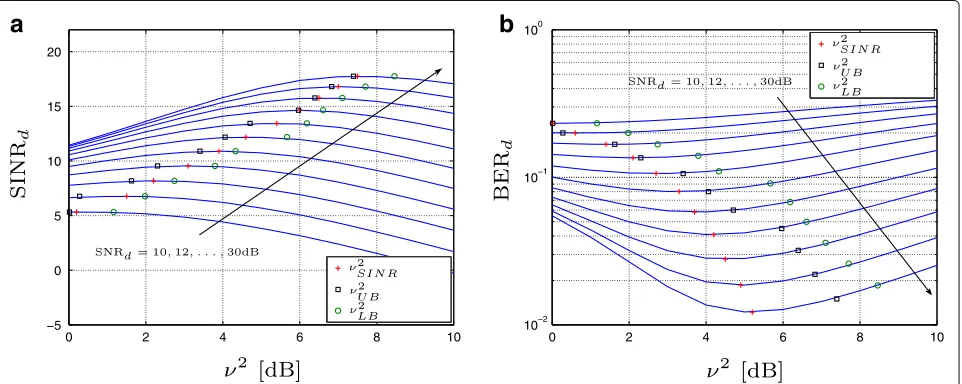
Fig. 2Maximization of SINRaand minimization of BERbfor the SL model and SNRd=10, 12,. . ., 30 dB. Rayleigh relay-destination channel
considered, i.e.,αRX = αTX = 1.02,θRX = θTX = 1.5◦, corresponding to an image rejection ratio (IRR) of 35 dB. We consider an ADC of 12 bits,κad =1,P(udc)=13 dB, and a delay of d = 5. The PA parameters are As = 1 for SL andAs = 1,p = 2 for SSPA. The SR channel is a static AWGN channel withLSR =3 and the SI channel is a Rician channel withLSI =3 and a K-factor1of 5 dB [1]. We consider two conditions for the relay-destination (RD) link, first a time-varying frequency-selective Rayleigh channel with LRD = 5 and then a static flat AWGN channel.
We assume that the channels are known. The SNR at the destination is defined as SNRd = E{|x(n)|2}/σd2 cor-responding to an ideal system. In the simulations, we implement the widely linear I/Q imbalance compensa-tion and SI cancellacompensa-tion proposed in [23] and replicated in Appendix 1.
In Fig. 2, we show the result of the numerical SINR max-imization (51) and BER minmax-imization (52), and compare them with the derived theoretical bounds (47) and (50), considering a frequency-selective relay-destination chan-nel and SNRd=10, 12,. . ., 30 dB. As expected, maximum values lie between the upper and lower bounds. It should be noted that the upper bound underestimates the opti-mum IBO whereas the lower bound overestimates it. Even when the error in IBO for BER optimization goes from 0.55 dB for SNRd =10 to 1.73 dB for SNRd =30 dB, the BER difference between the optimal value and the theoret-ical bounds is not very large since BER curves are rather flat around the optimum.
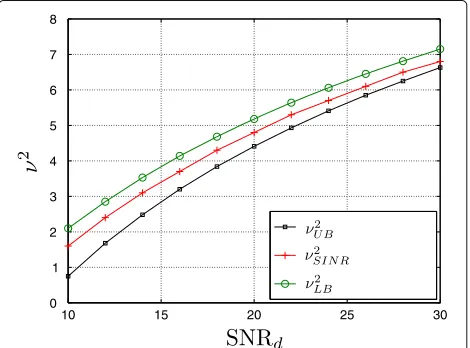
In Fig. 3, we plot the result of the numerical maximiza-tion of SINR, the upper, and the lower bound as a funcmaximiza-tion of the SNRd, for the same conditions than in Fig. 2. We have that as SNRd increases the difference between the
bounds becomes smaller, giving an accuracy of less than 1 dB for SNRdgreater than 16 dB.
The difference between the maximization of the SINR and the minimization of the BER is a consequence of the frequency-selectivity of the relay-destination channel. In other words, for a frequency-selective relay-destination channel, the optimization solutions do not coincide. To verify that concept, in Fig. 4 we show the SINR maximiza-tion and the BER minimizamaximiza-tion for a flat fading channel. It is clear that in this case the BER minimization solution also lies between the theoretical bounds.
When closed-form expressions of parameters κpa(ν) and Ppa(ν) are not available, Eqs. (42) and (41) can be solved numerically using the definitions in (5). In Fig. 5 we
Fig. 3The result of the numerical maximization of SINRνSINR2 , the upper boundνUB2 , and the lower boundνLB2 as a function of the SNRd,
Fig. 4Maximization of SINRaand minimization of BERbfor the SL model and SNRd=10, 12,. . ., 30 dB. Flat relay-destination channel
show the performance of the upper and the lower bound for the SINR and BER considering the SSPA model. We compare the results with the numerical solution of (51) and (52). As it can be noted, the curves are very similar to those obtained in Fig. 2.
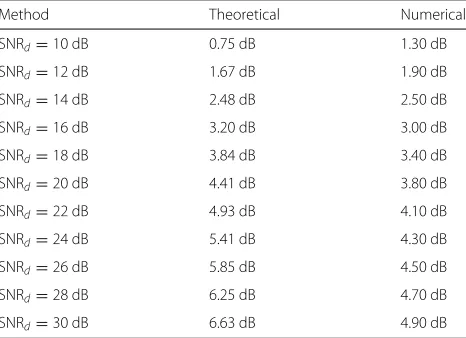
In Fig. 6, we show the BER for the two-hop relay link operating at the optimal point as a function of the SNRd, and compare the performance with fixed IBOsν2 =0, 2, 4, 6, and 8 dB. We include a theoretical and a numeri-cal optimal curve. The theoretinumeri-cal curve is obtained using the upper bound (since it is closer to the optimal IBO), where (50) is solved for each SNRd. The numerical curve is obtained using optimal values found in Fig. 2. Used
values for optimal solutions are included in Table 1. As expected, the numerical curve outperforms the others for every SNRd. The theoretical curve approximates well the numerical solution and performs better than curves with fixed IBOsν2=0, 2, 6, and 8 dB. The curve forν2=4 dB has a good performance since the optimal IBO is close to 4 dB from SNRds between 20 and 30 dB. This figure shows that the relay can operate with an optimal PA IBO, minimizing the BERd, if information of SNRdis available.
5 Conclusions
Setting the power amplifier (PA) input back-off (IBO) is a trade-off between the signal-to-noise ratio (SNR)
Fig. 6Theoretical and numerical optimal BER as a function of the SNRd. Fixed BER curves forν2=0, 2, 4, 6 and 8dB are included for
comparison
at the destination and the signal-to-interference-plus-noise (SINR) at the relay input. We derived expressions for bounding the optimal IBO that maximizes the SINR at the destination under RF impairments. In particular, we provided closed-form bounds for the soft limiter PA model and numerical solutions for more general mod-els. The bounds proved to be very close to the numerical solution of the optimal SINR minimization. Addition-ally, we demonstrated that the SNR at the relay input does not affect the IBO optimization. The optimal IBO that minimizes the BER can be bounded by the proposed expressions when the relay-destination channel is flat in frequency and it can be approximated with an acceptable error for frequency-selective channels. Finally, we showed
Table 1Results of the numerical and theoretical optimal IBOs as a function of the SNRdused in Fig. 6
Method Theoretical Numerical
SNRd=10 dB 0.75 dB 1.30 dB
SNRd=12 dB 1.67 dB 1.90 dB
SNRd=14 dB 2.48 dB 2.50 dB
SNRd=16 dB 3.20 dB 3.00 dB
SNRd=18 dB 3.84 dB 3.40 dB
SNRd=20 dB 4.41 dB 3.80 dB
SNRd=22 dB 4.93 dB 4.10 dB
SNRd=24 dB 5.41 dB 4.30 dB
SNRd=26 dB 5.85 dB 4.50 dB
SNRd=28 dB 6.25 dB 4.70 dB
SNRd=30 dB 6.63 dB 4.90 dB
that the relay can operate with the optimal IBO that mini-mizes the BER at destination, if information of the second hop SNR is available.
Appendix 1
Derivation of the coefficientsw1(n)andw2(n)of the canceler
In this section we reproduce for convenience the deriva-tion of zero-forcing (ZF) coefficientsw1(n)andw2(n)of the widely linear SI and SR channel canceler, presented in [23]. The coefficients are the result of the combination of three stages that address respectively the I/Q imbalance of the receiver mixer, the SR channel and SI distortion, and the I/Q imbalance of the transmitter mixer, as it is depicted in Fig. 7.
The “IQ RX” block is a widely linear post-cancellation filter that is the ZF solution for I/Q imbalance compensa-tion, viz.
uRM(n)=g1RXuad(n)+gRX2 u∗ad(n) (53)
where
g1RX = (κr) ∗
κr|2−χr|2 (54a)
g2RX = −χr
κr|2−χr|2
. (54b)
The output of SI and SR channel canceler can be written asuC(n) = uRM c(n). In a similar way than (53), the output of the widely linear pre-cancellation filter “IQ TX” can be written as
uw(n)=g1TXuC(n)+g2TXu∗C(n) (55)
where
g1TX = (κt) ∗
κt|2−χt|2 (56a)
g2TX = −χt
κt|2−χt|2
. (56b)
Since there are no noise sources between the filter and the up-conversion mixer, it is able to compensate perfectly the I/Q imbalance at the transmitter.
Finally, we can define the widely linear canceler of Fig. 1 as the combination of the three stages presented above as
w1(n) = (κr)
∗(κ
t)∗c(n)+χt(κr)∗c∗(n)
|κr|2− |χr|2 |κt|2− |χt|2
(57a)
w2(n) = −χr(κt)
∗c(n)−κ
rχtc∗(n)
|κr|2− |χr|2 |κt|2− |χt|2
(57b)
Fig. 7I/Q imbalance compensation and SR-SI equalization
To obtain an expression for C(z), we substitute (57) into (13). Then, we can write the relay output with I/Q imbalance compensation as
y(n) = κpaκad
xhsr(n−d)+yhsi(n−d)
c(n)
+κpa
[(κr)∗κtχt−(χr)∗κtχt]
|κr|2− |χr|2 |κt|2− |χt|2
ηad(n) c∗(n)
+κpa
|χt|2κr− |κt|2χr
|κr|2− |χr|2 |κt|2− |χt|2
η∗ad(n) c(n)
+κpaη(n−d) c(n)
+ηpa(n). (58)
Specifically, (58) shows that the equivalent model of the relay with I/Q imbalance compensation is linear with col-ored noise. Calculating itsz-transform and neglecting the noise, we can express the output of the relay as
Y(z)= κpaκadHsr(z)C(z)X(z)z −d
1−κpaκadHsi(z)C(z)z−d
. (59)
Finally, we can obtain the ZF solution of (58) by equat-ing (59) withκpaX(z)z−d. One may note thatC(z)does not compensate for the delay or the IBO. The canceler becomes
C(z)= 1
κad
Hsr(z)+κpaHsi(z)z−d
. (60)
Additionally, it is important to make sure thatC(z) is a stable filter in order to enable a practical implementa-tion. Considering a simplified scenario with a flat static SR channelHsr(z)= 1, single tap SI channelLsi = 1 and
Kpa = 0.38 (IBO = 8 dB and SL PA model). It is easy to show from (60) that the maximum allowable residual SI power, i.e., SI after antenna and RF cancellation, results 1/Kpa2 larger than the signal of interest. For the SL PA with an IBO = 8 dB, it equals∼4.3 dB.
Acknowledgements
Gustavo J. González, Fernando H. Gregorio, and Juan E. Cousseau were funded by the Universidad Nacional del Sur PGI 24/K058 and PGI 24/K059, the ANPCyT PICT-2012-1530, and the CONICET PIP 2012-2014 GI. Taneli Riihonen and Risto Wichman were partly funded by the Academy of Finland under project # 288249.
Competing interests
The authors declare that they have no competing interests.
Publisher’s Note
Springer Nature remains neutral with regard to jurisdictional claims in published maps and institutional affiliations.
Author details
1CONICET-Department of Electrical and Computer Engineering, Universidad
Nacional del Sur, Av. Alem 1253, Bahía Blanca, Argentina.2Department of Signal Processing and Acoustics, Aalto University School of Electrical Engineering, Helsinki, Finland.
Received: 16 July 2016 Accepted: 6 April 2017
References
1. M Duarte, C Dick, A Sabharwal, Experiment-driven characterization of full-duplex wireless systems. IEEE_J_WCOM.11(12), 4296–4307 (2012) 2. T Riihonen, R Wichman, in9th International Conference on Cognitive Radio
Oriented Wireless Networks and Communications (CROWNCOM). Energy detection in full-duplex cognitive radios under residual self-interference (IEEE, Oulu, 2014), pp. 57–60. doi:10.4108/icst.crowncom.2014.255395 3. D Korpi, T Riihonen, V Syrjälä, L Anttila, M Valkama, R Wichman, Full-duplex
transceiver system calculations: Analysis of ADC and linearity challenges. IEEE_J_WCOM.13(7), 3821–3836 (2014). doi:10.1109/TWC.2014.2315213 4. M Mohammadi, HA Suraweera, Y Cao, I Krikidis, C Tellambura, Full-duplex radio for uplink/downlink wireless access with spatially random nodes. IEEE_J_COM.63(12), 5250–5266 (2015).
doi:10.1109/TCOMM.2015.2495353
5. DWK Ng, Y Wu, R Schober, Power efficient resource allocation for full-duplex radio distributed antenna networks. IEEE_J_WCOM.15(4), 2896–2911 (2016). doi:10.1109/TWC.2015.2512919
6. A Mattsson, Single frequency networks in DTV. IEEE_J_BC.51(4), 413–422 (2005)
7. NH Tran, LJ Rodríguez, T Le-Ngoc, Optimal power control and error performance for full-duplex dual-hop AF relaying under residual self-interference. IEEE_J_COML.19(2), 291–294 (2015). doi:10.1109/LCOMM.2014.2385093
8. JI Choi, M Jain, K Srinivasan, P Levis, S Katti, inProceedings of the 16th Annual International Conference on Mobile Computing and Networking. Achieving single channel, full duplex wireless communication (ACM, Illinois, 2010), pp. 1–12. doi:10.1145/1859995.1859997. http://doi.acm. org/10.1145/1859995.1859997
9. E Everett, A Sahai, A Sabharwal, Passive self-interference suppression for full-duplex infrastructure nodes. IEEE_J_WCOM.13(2), 680–694 (2014). doi:10.1109/TWC.2013.010214.130226
10. K Haneda, E Kahra, S Wyne, C Icheln, P Vainikainen, inProceedings of the 4th European Conference on Antennas and Propagation (EuCAP). Measurement of loop-back interference channels for outdoor-to-indoor full-duplex radio relays (IEEE, Barcelona, 2010), pp. 1–5
11. A Raghavan, E Gebara, EM Tentzeris, J Laskar, Analysis and design of an interference canceller for collocated radios. IEEE_J_MTT.53(11), 3498–3508 (2005)
12. B Debaillie, D-J van den Broek, C Lavin, B van Liempd, EAM Klumperink, C Palacios, J Craninckx, B Nauta, A Pärssinen, Analog/RF solutions enabling compact full-duplex radios. IEEE_J_JSAC.32(9), 1662–1673 (2014). doi:10.1109/JSAC.2014.2330171
13. T Riihonen, S Werner, R Wichman, Mitigation of loopback self-interference in full-duplex MIMO relays. IEEE_J_SP.59(12), 5983–5993 (2011) 14. D Korpi, L Anttila, V Syrjälä, M Valkama, Widely linear digital
self-interference cancellation in direct-conversion full-duplex transceiver. IEEE_J_JSAC.32(9), 1674–1687 (2014). doi:10.1109/JSAC.2014.2330093 15. R Lopez-Valcarce, E Antonio-Rodriguez, C Mosquera, F Perez-Gonzalez, 1566–1577. IEEE_J_JSAC.30(8) (2012). doi:10.1109/JSAC.2012.120923 16. G González, F Gregorio, J Cousseau, in48th Asilomar Conference on Signals,
17. T Riihonen, R Wichman, in46th Asilomar Conference on Signals, Systems and Computers. Analog and digital self-interference cancellation in full-duplex MIMO-OFDM transceivers with limited resolution in A/D conversion (IEEE, Pacific Grove, 2012). doi:10.1109/ACSSC.2012.6488955 18. E Ahmed, AM Eltawil, A Sabharwal, in47th Asilomar Conference on Signals,
Systems and Computers. Self-interference cancellation with nonlinear distortion suppression for full-duplex systems (IEEE, Pacific Grove, 2013), pp. 1199–1203. doi:10.1109/ACSSC.2013.6810483
19. L Anttila, D Korpi, V Syrjälä, M Valkama, in47th Asilomar Conference on Signals, Systems and Computers. Cancellation of power amplifier induced nonlinear self-interference in full-duplex transceivers (IEEE, Pacific Grove, 2013), pp. 1193–1198. doi:10.1109/ACSSC.2013.6810482
20. A Masmoudi, T Le-Ngoc, inIEEE International Conference on Communications (ICC). A digital subspace-based self-interference cancellation in full-duplex MIMO transceivers (IEEE, London, 2015), pp. 4954–4959. doi:10.1109/ICC.2015.7249108
21. D Korpi, L Anttila, M Valkama, inIEEE Globecom Workshops. Reference receiver based digital self-interference cancellation in MIMO full-duplex transceivers (IEEE, Austin, 2014), pp. 1001–1007.
doi:10.1109/GLOCOMW.2014.7063564
22. T Riihonen, S Werner, F Gregorio, R Wichman, J Hämäläinen, inIEEE Wireless Communication and Networking Conference. BEP analysis of OFDM relay links with nonlinear power amplifiers (IEEE, Sydney, 2010), pp. 1–6. doi:10.1109/WCNC.2010.5506301
23. G González, F Gregorio, J Cousseau, T Riihonen, R Wichman, inEuropean Wireless (EW) conference. Performance analysis of full-duplex AF relaying with transceiver hardware impairments (IEEE, Oulu, 2016)
24. M Awadin, N Al-Dhahir, R Hamila, OFDM full-duplex DF relaying under I/Q imbalance and loopback self-interference. IEEE_J_VT.PP(99), 1–1 (2015). doi:10.1109/TVT.2015.2479257
25. A Tarighat, R Bagheri, AH Sayed, Compensation schemes and performance analysis of IQ imbalances in OFDM receivers. IEEE_J_SP.
53(8), 3257–3268 (2005). doi:10.1109/TSP.2005.851156
26. T Riihonen, P Mathecken, R Wichman, in46th Asilomar Conference on Signals, Systems and Computers. Effect of oscillator phase noise and processing delay in full-duplex OFDM repeaters (IEEE, Pacific Grove, 2012). doi:10.1109/ACSSC.2012.6489379
27. J Minkoff, The role of AM-to-PM conversion in memoryless nonlinear systems. IEEE_J_COM.33(2), 139–144 (1985).
doi:10.1109/TCOM.1985.1096262
28. D Dardari, V Tralli, A Vaccari, A theoretical characterization of nonlinear distortion effects in OFDM systems. IEEE_J_COM.48(10), 1755–1764 (2000). doi:10.1109/26.871400
29. IS Gradshteyn, IM Ryzhik,Table of Integrals, Series, and Products, 7th ed. (Academic Press, London, 2007)
30. M Abramowitz, IA Stegun,Handbook of Mathematical Functions with Formulas, Graphs, and Mathematical Tables. (Dover Publications, Washington DC, 1972)
Submit your manuscript to a
journal and benefi t from:
7Convenient online submission
7Rigorous peer review
7Immediate publication on acceptance
7Open access: articles freely available online
7High visibility within the fi eld
7Retaining the copyright to your article