R E S E A R C H
Open Access
Resource allocation for relay-assisted OFDMA
systems using inter-cell interference coordination
Hongtao Zhang
1*, Xiaoxiang Wang
1, Yang Liu
2, LZ Zheng
1and Thomas Michael Bohnert
3Abstract
This article proposes a new enhanced fractional frequency reuse (FFR) scheme to improve the system performance in multi-cell orthogonal frequency division multiple access system, which tackles the problems of frequency distribution and inter-cell interference (ICI) by jointly FFR and ICI coordination. The proposed scheme dynamically assigns subcarriers to center and edge groups depending on load conditions and the channel state information by two algorithms. The center allocation algorithm assigns subcarriers to center users from different directions. The edge allocation algorithm allows the highly loaded sectors to borrow the remaining subcarriers from center band or other sectors considering the fairness requirements of all the users. Simulation results illustrate that the proposed scheme can outperform the traditional schemes by achieving higher throughputs and better spectral efficiency especially in highly loaded cells.
Keywords:frequency distribution, multi-cell OFDMA, fractional frequency reuse (FFR), ICI coordination.
1. Introduction
In the Long-Term Evolution (LTE) advanced systems, they are confronted with the limited resource for high spectral efficiency (SE) and large coverage [1]. By intro-ducing relay station (RS) into a cellular network, we can extend the cell coverage, save the transmitting power and improve the link quality.
The major reason for performance degradation in orthogonal frequency division multiple access (OFDMA) system is the inter-cell interference (ICI). In particular, users at the cell-edge may have relatively low signal-to-interference-plus-noise ratio (SINR) because such loca-tions suffer severely from ICI.
Several frequency distribution schemes have been sug-gested to improve the system data rate of an OFDMA system. Among those are soft frequency reuse (SFR) [2] and a more efficient modified SFR (MSFR) frequency allocation scheme [3]. In particular, MSFR is a better tradeoff between the frequency reuse factor and the ICI. MSFR can highly improve the throughput and the SE. However, it cannot be adapted to non-homogeneous networks.
For mitigating ICI, several methods [4-7] have been proposed to avoid interference between cells. A static ICI coordination scheme is studied in [4], which simpli-fies the frequency distribution and achieves good chan-nel gain. However, it can only achieve a low SE. Based on [4], semi-static ICI coordination schemes are pro-posed in [5,6] to improve the SE. The subcarriers distri-bution is decided by both the radio network controller and the base stations (BSs). This algorithm can coordi-nate interference and assign subcarriers to the BSs. However, it cannot fulfill all the users’requirements and has a reuse multiuser diversity gain. The combination of ICI coordination with cancellation or beamforming in [7] is a complementary to each other and to some extent improving the performance.
Dynamic frequency allocation (DFA) has widely been studied for multi-cell cellular networks [8-10]. Power allocation (PA) to different subcarriers can improve sys-tem data rate, so many studies have been done by joint DFA and PA in OFDMA networks. Partial isolation scheme for LTE system has been analyzed in [8]. It uses different transmission powers in different frequency bands in order to reduce interference at cell-edge. The subcarriers distribution in [9] considers the tradeoff between the ICI mitigation and SE. However, previous * Correspondence: [email protected]
1Key Laboratory of Universal Wireless Communication, Ministry of Education, Beijing University of Posts and Telecommunications, Beijing 100876, P.R. China
Full list of author information is available at the end of the article
study [10] has indicated that the performance improve-ments are limited.
Fractional frequency reuse (FFR) statically divides sub-carriers into two overlapping regions, which are called center band and edge band [11]. The subcarriers distri-bution is statically depending on the distance from the serving BS or the SINR thresholds. The edge subcarriers are further divided into three sectors and reused in the edge regions. However, FFR scheme divides users just on the basis of the distance or SINR thresholds, which reduces the link gain. The subcarriers distribution does not consider the channel state information, so it cannot fit for the rapid changes of networks.
The MSFR and static FFR schemes statically divide subcarriers into cells and do not consider the load con-ditions. In order to overcome the shortcomings of these two allocation schemes and improve multi-cell system performance, we propose enhanced FFR scheme (EFFR) by jointly dynamically subcarriers distribution and inter-ference coordination between cells. To increase the link gain, there are no obvious boundaries between center and edge regions. The proposed center allocation algo-rithm assigns subcarriers according to the load and the channel state information to improve the system data rate. The BS schedules subcarriers to center users from different directions in different cells. The edge allocation algorithm divides subcarriers into three sectors and allows users to borrow remaining subcarriers from cen-ter group and other sectors, which can meet the fairness requirements of users.
2. System model
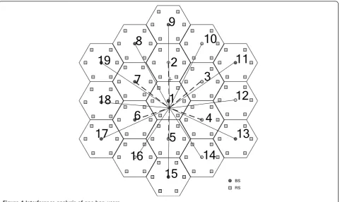
The downlink of an OFDMA-based two-hop cellular system is considered. As shown in Figure 1, each cell has one BS and six relays which are located at the cell-center and edge, respectively. Assuming that the cell radius is Rand each RS is about 2/3 of cell radius away from the BS. A user equipment can communicate either directly with a BS by a one-hop link or by a two-hop link via fixed RS. The direct link between MS and BS is referred to as the access link while the link between RS and BS is referred to as the relay link. The one-hop user is mainly interfered by the neighboring BSs and the interfering sources of a two-hop user are all the RSs which use the same band with its serving RS.
2.1. EFFR cell architecture
In MSFR and static FFR schemes, all the users and sub-carriers are statically partitioned into two groups namely center and edge groups. The edge frequency utilization of these two schemes is unsatisfactory and these kinds of allocation do not consider the changes of system load. The proposed scheme aims to overcome the short-comings of these two allocation schemes. Figure 2a
shows the frequency band allocation of the proposed scheme. We see from this figure that the entire band-width is divided into two main groups: center band (A) and edge band (B, C, andD). All the cells in the grid reuse a portion of subbands and the edge users usebi portion of subbands, wherea+ (b1+b2+b3) = 1. Figure 2b shows the proposed cell frequency planning architec-ture. In this architecture, cell-edge is further partitioned into three sectors. The center frequency band (A) is shared by all the center regions to serve the one-hop users. The edge band (D) is used for relay links in cell 1. The edge band (C) is reused by cell 2, 4, 6 and the edge band (B) is reused by cell 3, 5, and 7.
The resource partitioning to center and edge group is proportional to the numbers of users based on center allocation algorithm. The edge allocation algorithm assigns subcarriers to the sectors considering both the channel state information and the load conditions. By borrowing subcarriers from center group or other sec-tors, the edge users can obtain a better gain than the static FFR scheme. Furthermore, the dynamically distri-bution can effectively avoid the ICI by scheduling sub-carriers with interference coordination between sectors and also improve the edge-cell performance. In this arti-cle, we study 19-cell grids with 3 sectors per cell.
2.2. System model
In this OFDMA cellular network, the total number of cells isK, so we haveK- 1 adjacent cells, numbered 2 toK, the main cell being number 1. LetMkbe the number of users in a cellk, wherek= 1 ...K. LetMck denote the number of center users in a cellk, so the total number of users is
M = K
k=1Mk. In the proposed architecture, the edge
group is divided intoLsectors and Mlk is the number of users in thelth sector of a cellk, so Mk=
The frequency band ofNsubcarriers is divided intoW subchannels and the set of bands is denoted byB= {B
cen-ter,Bedge}. Letykdenote the set of subcarriers borrowed from center band and yck=Bck be the number of remain-ing subcarriers borrowed from center band in a cell k.
ξk=ξkl denotes the number of remaining subcarriers
bor-rowed from thelth sector of a cellk.
3. Frequency allocation schemes
subcarriers distribution, we propose both center and edge allocation algorithms. Detailed description of the two algorithms is given as follows.
3.1. Center allocation algorithm
The BS can collect the SINR and the channel state information and then use them to assign subcarriers between center and edge group. In the center allocation algorithm, the choice of the“regions”of subcarriers allo-cation depends on the load of the cell and its neighbor-ing cells. This is illustrated in Figure 3a. Cell 2 is highly loaded and cell 1 has a low load, so the region of fre-quency band (A) is then larger in cell 2 than in cell 1.
From Figure 3b, we can see the direction that BSs schedule subcarriers in different cells. The BS in cell 2 schedules available subcarriers from the center of band-width in both the left and the right directions. The BS in cell 1 schedules available subcarriers from the left of bandwidth while the BS in cell 3 schedules subcarriers from the right of bandwidth. By using this proposed algorithm to schedule subcarriers, the remaining subcar-riers in different cells are different parts of A and will have a low probability of overlap. The cell-edge users can also borrow the remaining subcarriers to meet their requirements with less interference.
3.2. Edge allocation algorithm
The edge allocation algorithm divides the edge band into three parts for different cells and each cell is parti-tioned into three sectors.
Assuming that a threshold n1 can meet the users’ minimum data rate requirement and sectorD1 is highly loaded. The subcarriers allocation scheme can be described as follows:
(a) We can first schedule the remaining subcarriers of center band in cell 1. If there is no remaining subcar-riers or it still cannot meet the users rate requirements, go to step (b)
(b) If the distribution of the subcarriers to sectorB1 orC1 is remaining, the algorithm schedules the remain-ing subcarriers of these sectors.
(c) If sectorB1 orC1 is highly loaded, go to step (d). (d) If all the users in sector D1 now still cannot meet users’data rate requirements and the sector B2 (orB3 or C2 or C3) has remaining subcarriers, the algorithm will schedule the remaining subcarriers from these sec-tors with a reduced powerP2 for transmission.
(e) If all the users in sector D1 now can meet users’ data rate requirements, stop. Other highly loaded sectors can also use the same methods to borrow the remaining subcarriers. The edge allocation algorithm can be effec-tive in improving the throughput of low SINR users at the cell edge.
4. Performance analysis
The proposed frequency planning scheme aims to rea-lize a high throughput and low outrage performance. In this section, we analysis the interference of MSFR, static FFR, and the proposed scheme and calculate the average SINR and throughput. The calculation results must be
1
1
Interfering
BS
Serving
BS
Two-hop user
One-hop user
RS
performed taking into account the path loss and shadowing.
4.1. Center allocation algorithm
4.1.1. Subcarriers partition
The algorithm first distributes subcarriers into center and edge group depending on the number of users in different regions. The ratio of band between center and edge can be expressed as
α wherej1 denotes the max number of center users in all cells andj2 denotes the max number of edge users
A
B
C
D
BS-RS and direct link cell-edgeof 3.5.7 cell-edgeof 2.4.6 cell-edgeof 1
D
E
1Center band Edge band
2
in cell 2, 4, 6. j3 represents the max number of edge users in cell 3, 5, 7.
4.1.2. SINR
For one-hop users, the interference case can be seen in Figure 4. All the center cells reuse the center band, so the one-hop users served by BS are interfered by all the BSs.
We assume that the power of user ifrom its own BS can be formulated as
Pkb=PBSk Gbk,i (3) where bÎ Bcenter represents the center band andPBSk
denotes the transmit power of BSk. Gbk,i is the channel gain between user iand its own serving BSkon bandb. The channel gain takes into account the path loss, sha-dowing, and fast fading.
As for users in the center cell area, they use the sub-channel with the reuse 1 subband. The useriin cell 1 is interfered by the surrounding 18 BSs. Then, the interfer-ence power of user i received from a neighbor BS can be written as
PIb=
K
k=2
PBS1 Gbi,j (4)
where k Î K is the cell number. Gbi,j denotes the
channel gain between useriand its interference BSjon bandb.
Therefore, the received SINR for one-hop user ifrom its own BS1 on bandbcan be expressed as
SINRbi,1= P
b
1 PbI +PN
= P
BS 1 Gbi,1
K
j=2 PBS
j Gbi,j+N0f
(5)
where N0 is the power spectrum density of AWGN,
and Δf is the neighboring subcarrier spacing. We
assume that all users have the same noise level.
4.2. Edge allocation algorithm
4.2.1. MSFR
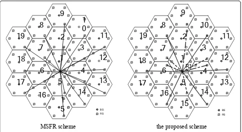
The interference case is shown in Figure 5. A user in cell 1 is interfered by R1 in the surrounding 18 cells. The received SINR of user iin cell 1 can be expressed as
SINRvi,1= P
R1
1,νGvi,1
K
j=2 PR1
j Gvi,j+N0f
(6)
where PR1
1,ν is the transmitted power fromR1 in cell 1.
vÎBedgerepresents the edge band.
4.2.2. EFFR
The algorithm first considers the sectors which cannot meet the data rate requirements of their users. If all the sectors can meet their users’requirements, then a user i of sector D1 in cell 1 is interfered by R1 in six cells: 8,
RS MS BS
1
3 2
4
5
6
1
2
3
7
(a)
Cell 1 Cell 2 Cell 3
(b)
10, 12, 14, 16, and 18. The interference power of user i received from a neighbor R1 can be written as
PIv=PRmaxGvi,8+PRmaxGiv,10+PRmaxGvi,12+PRmaxGvi,14 +PRmaxGv
i,16+PRmaxGvi,18
(7)
We assume that sectorD1 in cell 1 cannot meet their load requirement. The algorithm will search other sec-tors which have remaining subcarriers. If sectorB1 in cell 3, 5, 7 has remaining subcarriers, then we will bor-row these subcarriers. Now, the increased interference power of a userican be written as:
PIω=PR1Gω
i,3+PR1Gωi,5+PR1Gωi,7 (8)
whereω∈ξkB1 denotes the number of remaining sub-carriers borrowed from sectorB1 of cellk, wherek= 3,5,7. If sectorC2 in cell 2, 4, 6 has remaining band, we will borrow these remaining subcarriers to meet the load requirement. A useri may also be interfered by R5 in cell 2, 4, 6. The increased interference power of a user i can be written as
PςI =PwR5Gwi,2+PRw5Gwi,4+PwR5Gwi,6 (9)
wherew∈ξkC1represents the number of remaining sub-carriers borrowed from sectorC1 of cellk(k= 2, 4, 6).
So, the received SINR for two-hop user iin cell 1 can be expressed as
SINRei =
PRmax
I G v,R1
i,1 Pv
I+λ1PIw+λ2PςI +N0f
(10)
where l1 is an index variable withl1 = 1 implying that the remaining subcarriers are borrowed from sector B1 andl1 = 0 otherwise.l2 is an index variable withl2 = 1 implying that the remaining subcarriers are bor-rowed from sectorC1 andl2= 0 otherwise.
The average link quality determines the performance of the system. Hence, the average cell-edge SINR is
SINRedge=
k∈K
SINRk K
k=1
L
l=1 Ml
k
(11)
where Mlk is the number of the lth sector users in cellk.
4.2.3. Cell throughput
The transmitted data rate of userion subcarrierjin cell kcan be given as
Ri,j,k=B∗log2(1 +λSINRi,j,k) (12)
1
2
3
4
5
6
7
8
9
10
11
12
13
14
15
16
17
18
19
RS BS
whereB* is the total bandwidth of the assigned sub-carriers for the ith user.lis a constant which is related to the target bit error rate (BER) and can be specified as [12]
λ= −1.5
ln(5BER) (13)
So, the total throughput is
Ri=
whereci, jis an assignment index variable withci, j= 1 implying that subcarrierjis assigned to useriandci, j = 0 otherwise.
4.2.4. SE and outage probability
Under the assumption that users are uniformly distribu-ted, the outage probability is defined as the probability that the throughput falls below a prescribed level R
thres-hold. It is formulated as
Pout=Pr(Ri<Rthreshold) (15)
The SESE of cell load is defined as
Peff=
1
NKlog2(1 + SNRthreshold)
K the number of cell-edge users.
5. Simulation results
In this section, we compare the proposed scheme with the MSFR and static FFR schemes. The simulation para-meters are given in Table 1. In the proposed scheme, the subcarriers are dynamically partitioned according to the cell load. The BS schedules subcarriers to center users opportunistically from different directions. The edge allocation algorithm divides the users into three sectors. The highly loaded sector can also schedule those remaining subcarriers from cell-center or other edge sectors. The static FFR scheme just assigns subcar-riers according to a distance threshold from the serving BS.
Figure 5Interference analysis of different schemes.
Table 1 Main simulation parameters
Parameter Value
Carrier frequency 2 GHz Channel bandwidth 5 MHz Cell radius (R) 500 m Shadowing deviation 8 dB Relay location 2R/3 Subcarrier number 64 BS transmit power 43 dBm
Grid layout 3-sectored hexagonal 19 cells
N0 -174 dBm/Hz
Number of users in cell-edge 30 Relay number each cell 6
Figure 6 compares the cumulative distribution func-tions (CDF) of received average SINRs of users. The fig-ure shows that the SINRs of system have significantly improved over the conventional cellular system without relay. Among the four schemes, the proposed scheme provides best performance. That is because our algo-rithm divides the edge subcarriers into three sectors and these subcarriers can be reused at the edge zones. For this scheme, there is a reduced interference from the adjacent cells and the intelligently subcarriers allocation increases the signal gain.
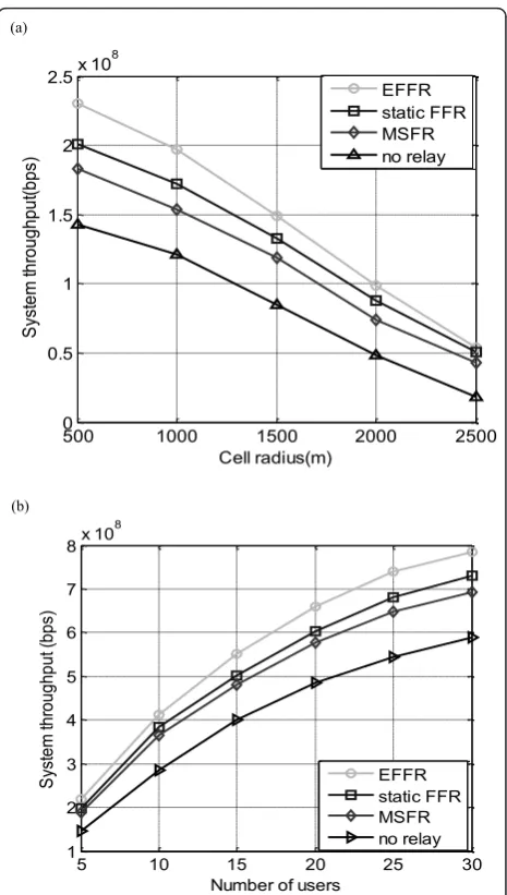
Figure 7a, b compares the system throughput received by users in all the cells of four different schemes. In MSFR, although the frequency reuse factor of both cell-center and cell-edge are 1, the throughput is not high. The reason is that only one-third of the frequency resources can be used in each cell-edge. From Figure 7a, we can see that the throughput of users is reduced with the increased cell radius. This reduction is due to the increased path loss. The throughput of relay schemes achieve better than the system without relay. When the cell radius is small, our proposed scheme can benefit about 15% improve-ment than static FFR from the positive subcarriers allocation. For cell radius 2 km or higher, the advan-tage of our proposed scheme is not obvious. The rea-son is that there is little interference and low-signal power. Figure 7b shows that the throughput of our proposed scheme can obviously outperform than other schemes. That is because the proposed scheme assigns subcarriers proportional to the number of users in cells.
We compare the average SE of users at different loca-tion from BS in Figure 8. The figure shows that the SE of the proposed scheme is higher than the other three
schemes. The reason is that we assign the subcarriers among center and edge considering load and the edge users can borrow other sectors or center band to meet their requirements. The static FFR scheme distributes subcarriers statically depending on the distance from the serving BS. The subcarrier partitioning does not con-sider their load conditions. The MSFR scheme is suita-ble for homogeneous load distribution, so the proposed scheme has higher SE than others.
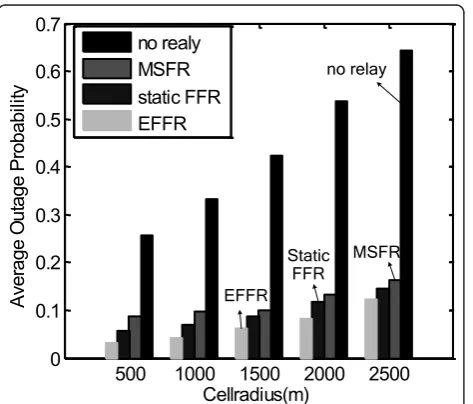
The average outage probability is illustrated in Figure 9 for four different schemes in different cell radius. We can easily notice that the outage probability increases with the increase of cell radius due to the increased path loss and reduced signal power. The average outage probability of proposed scheme is about 3% of 500 m,
0 10 20 30 40 50 60 70
Figure 6CDF of received average SINRs of users.
500 1000 1500 2000 2500
0
Number of users
S
which is the best performance in comparison to other schemes. The proposed scheme shows about 18% improvement than static FFR scheme. This can be explained that the subcarriers are allocated from center to edge and every cell-edge users have the equality chance to obtain subcarriers. Because cell edge users have higher interference, the edge algorithm allows users to borrow the remaining subcarriers from center or other sectors and this can provide the maximum gain to the performance.
6. Conclusions
In this article, we show an efficient frequency allocation scheme to plan the frequency allocation and reduce the
ICI in OFDMA cellular system. The proposed scheme contains the optimal center and edge allocation algo-rithms. The center allocation algorithm partitions sub-carriers into two main groups considering load conditions and the channel state information. The cen-ter subcarriers are scheduled from different directions in different cells. The users in the center group are inter-fered by all the neighboring 18 cells in the grid. The edge allocation algorithm assigns edge bands into three sectors and the subcarriers are reused in edge region of some cells. The highly loaded sector can borrow the remaining subcarriers from other sectors or cell-center regions, which provides high gain for the edge users. The dynamic distribution of subcarriers according to load and channel state information helps the proposed scheme to perform better than other conventional schemes. Simulation results compare the performance of these schemes and demonstrate that our proposed scheme reduces about 18% outage probability than tra-ditional FFR scheme.
Acknowledgements
This study was supported by the Fundamental Research Funds for the Central Universities (2011RC0112, 2011RC2J12), and the NSFC (60972076, 61072052).
Author details
1Key Laboratory of Universal Wireless Communication, Ministry of Education, Beijing University of Posts and Telecommunications, Beijing 100876, P.R. China2School of Electronic Engineering, Beijing University of Posts and Telecommunications, Beijing 100876, P.R. China3Zurich University of Applied Sciences, Zurich, Switzerland
Competing interests
The authors declare that they have no competing interests.
Received: 15 June 2011 Accepted: 1 May 2012 Published: 1 May 2012
References
1. R Pabst, Relay-based deployment concepts for wireless and mobile broadband radio. IEEE Commun Mag.42(9), 80–89 (2004)
2. 3GPP R1-050507, Huawei, Soft frequency reuse scheme for UTRAN LTE (2005)
3. L Guan, JH Zhang, JN Li, GY Liu, P Zhang, Spectral efficient frequency allocation scheme in multihop cellular network. inProc of IEEE Veh Tech Conf. MD, USA 1446–1450 (October 2007)
4. 3GPP R1-050407, Alcatel, Interference Coordination in new OFDM DL air interface (2005)
5. 3GPP R1-051085, San Diego, Resource Allocation for Interference Mitigation with Symbol Repetition in E-UTRA Downlink (2005)
6. 3GPP R1-051137, San Diego, Further results on inter-cell interference mitigation based on IDMA (2005)
7. 3GPP R1-060416, Huawei, Combining Inter-cell interference coordination/ avoidance with cancellation in downlink and TP (2006)
8. SE Elayoubi, OB Haddada, B Fourestie, Performance evaluation of frequency planning schemes in OFDMA-based networks. IEEE Trans Wirel Commun. 7(5), 1623–1633 (2008)
9. D Liang, WB Wang, A frequency reuse partitioning scheme with successive interference cancellation for OFDM downlink transmission. inProc of Int Conf on Telecommun Marrakech, Morocco 377–381 (May 2009)
10. G Song, YG Li, Cross-layer optimization for OFDM wireless networks–part I: theoretical framework. IEEE Trans Wirel Commun.4(2), 614–624 (2005)
0 100 200 300 400 500
Location from BS
A
Figure 8Average SE for different allocation schemes.
500 1000 1500 2000 2500
0
11. HP Lei, L Zhang, Xi Zhang, DC Yang, A novel multi-cell OFDMA system structure using fractional frequency reuse. inProc of IEEE Int Symp on Personal, Indoor and Mobile Radio Commun Athens, Greece 1–5 (September 2007)
12. X Qiu, K Chawla, On the performance of adaptive modulation in cellular systems. IEEE Trans Commun.47(6), 884–895 (1999)
doi:10.1186/1687-1499-2012-156
Cite this article as:Zhanget al.:Resource allocation for relay-assisted OFDMA systems using inter-cell interference coordination.EURASIP Journal on Wireless Communications and Networking20122012:156.
Submit your manuscript to a
journal and benefi t from:
7Convenient online submission
7Rigorous peer review
7Immediate publication on acceptance
7Open access: articles freely available online
7High visibility within the fi eld
7Retaining the copyright to your article