© 2015, IRJET.NET- All Rights Reserved
Page 274
Analysis of Single and Multi Resonance Point in Reactance
Characteristics of TCSC Device
Manojkumar Patil
1, Santosh Kompeli
21
Student (M.E.) Electrical Engineering Department, MSS’S COE, Jalna, Maharashtra, India
2Assistant Professor, Electrical Engineering Department, MSS’S COE, Jalna, Maharashtra, India
---***---Abstract:
It was always recognized that ac power transmission over long lines was primarily limited by the series reactive impedance of the line. Thyristor controlled series compensator (TCSC) device is a series compensator to govern the power flow by compensating the reactance of the transmission line. This paper presents a conceptual study to adopt an optimum value for the capacitor and inductor of a TCSC device. Degree of Series compensation (K) brings an idea of selecting the TCSC capacitor. The Reactance characteristic curve is analyzed with resonant point for different values of ‘ω’ which defines the square root of ratio between capacitive and inductive reactance. The study is helpful in selecting an appropriate value for TCSC inductor which has influence on multi resonance point in TCSC device.Key Words:
FACTS, TCSC, Reactance Characteristics
Curves, Resonance Points.
1. INTRODUCTION
Flexible AC Transmission System (FACTS) is an emerging technology which improve power transfer scenario around the world. It improves the power transfer capability of existing transmission system with enhances reliability and security of the system. Also achieve better controllability with stability in power transmission networks. In place of building new transmission line, installing FACTS devices in existing networks is more economical. Due to these advantages, FACTS technology is now adopted by many countries like Brazil, China, India etc.. Installing of FACTS devices in developing nation like India where power demand rate is very high and increasing constantly, is very helpful to improve transmission system with great economy. [1]
FACTS devices can be connected to a transmission networks in many ways, such as in series, shunt, or a combination of series and shunt. Like, thyristor controlled series capacitor (TCSC) and static synchronous series compensator (SSSC) are connected in series; the static VAR compensator (SVC) and static synchronous compensator (STATCOM) are connected in shunt and unified power flow controller (UPFC) are connected in a series and shunt combination. Series FACTS devices
increase stability and Shunt FACTS devices provide reactive power compensation.[2]
2. TCSC Device
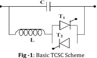
Thyristor-controlled series capacitors (TCSC) is also a type of series compensator, can provide many benefits for a power system including controlling power flow in the line, damping power oscillations and mitigating sub -synchronous resonance. The TCSC concept is that it uses an extremely simple main circuit. The capacitor is inserted directly in series with the transmission line and the thyristor-controlled inductor is mounted directly in parallel with the capacitor. Thus no interfacing equipment like e.g. high voltage transformers is required. This makes TCSC much more economic than some other competing FACTS technologies. Thus it makes TCSC simple and easy to understand the operation.[2-3]
Fig -1: Basic TCSC Scheme
World’s first 3 phase, 2 X 165 MVAR, TCSC was installed in 1992 in Kayenta substation, Arizona. It raised the transmission capacity of transmission line by 30%, but it was soon realized that the device is also a very effective means for providing damping of electromechanical power oscillations. A third possible application of TCSC emerged from the on site observations that it can provide series compensation without causing the same risk for sub synchronous resonance (SSR) as a fixed series capacitor. World’s first TCSC for subsynchronous resonance (SSR) mitigation was installed in Stode, Sweden in 1998, by ABB.[3-4]
Raipur-© 2015, IRJET.NET- All Rights Reserved
Page 275
compensating capacitor shunted by a Thyristor controlled reactor (TCR). TCR is a variable inductive reactor XLcontrolled by firing angle α.
Fig -2: Equivalent circuit of TCSC
Here variation of XL with respect to α is given by
XL (α) = XL
(1)
XC =
(2)
For the variation of α from 0° to 90°, XL (α) varies from
actual reactance (XL) to infinity. This controlled reactor is
connected across the series capacitor, so that the variable capacitive reactance, as shown in Fig.-2, is possible across the TCSC which modify the transmission line impedance.
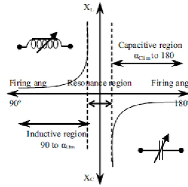
Fig.-3 shows TCSC Reactance Characteristic curve of TCSC Device. It is drawn between effective reactance of
TCSC and firing angle α [3]. The effective reactance of TCSC operates in three region, inductive region, capacitive region and resonance region as shown in Fig-3
Fig-3 Reactance Vs Firing Angle Characteristics Curve
2.3 RELATION BETWEEN THE TCSC RESONANT
POINT AND X
C, X
LFrom equation 3, it shows the relation between ω and XTCSC(α). The effective reactance XTCSC(α) would be
infinity when,
ω(π-α) = (2m ) ; (m= 1,2,3….) (7) It is clear from equation (7), That TCSC may appear multiple resonant points in 90° to 180° of firing angle(α). However, only one resonant point, namely one capacitive range and one inductive range is practically allowable. In this paper efforts has been made to obtain reactance characteristics of TCSC for various values of, Capacitor, Inductor & ω. Multiple resonant point will reduce the the operating range of the TCSC. Thus some measures has to be taken to ensure only one resonant point between 90° to 180° of firing angle(α).
3.ANALYSIS OF SINGLE RESONANT POINT
REACTANCE CHARATCRISTICS
For a practical TCSC, the compensation capacitance depends on the requirement of power system in which the TCSC is installed. Once the capacitance of compensation capacitor is fixed, the main factor influencing resonant point of TCSC is the reactance XL . To
© 2015, IRJET.NET- All Rights Reserved
Page 276
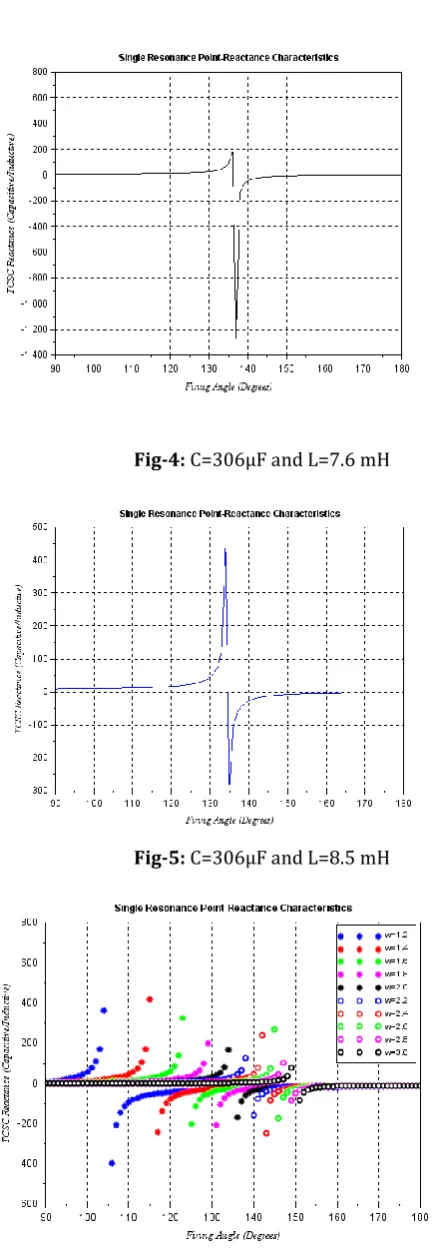
Fig-4: C=306µF and L=7.6 mH
Fig-5: C=306µF and L=8.5 mH
Fig-6: Single Resonance Point Reactance Characteristics
curve for ω=1.2 to 3.0
From equation (7) and Fig-4,5 & 6 it is clear that factor ω decides the range of inductive and capacitive region in TCSC and operating range of TCSC. In many literature authors refereed that factor ω should be less than 3[3-4].
ω = < 3 (8)
TABLE -1
SHIFT IN RESONANCE REGION FOR VARIOUS VALUES OF ω larger and for ω=3 the capacitive region shrinks to small.
4.ANALYSIS
OF
MULTI
RESONANT
POINT
REACTANCE CHARATCRISTICS
The various values of ω are considered while
analyzing the multi resonant point reactance
© 2015, IRJET.NET- All Rights Reserved
Page 277
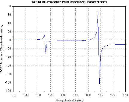
between 90° to 180° of firing angles on the TCSC for different values of ω which greater than 3.
Fig-7: Multi Resonance Point Reactance Characteristics
curve for ω=4.2
Fig-8: Multi Resonance Point Reactance Characteristics
curve for ω=3.2 to 5.2
TABLE -2
MULTI RESONANCE POINT FOR VARIOUS VALUES OF ‘ω’ GREATER THAN 3
ω = sqrt(XC/XL)
Multi Resonance Region Between the firing Angles(Degrees)
I II
3.2 100-101 152-154
4.2 115-116 158-159
5.2 127-129 161-162
5.
ANALYSIS
OF
TCSC
REACTANCE
CHARATCRISTICS FOR X
C= X
L, X
C< X
L(ω 1)
If both XC and XL are same, then factor ‘ω’
becomes 1 and meets resonance condition. When it is less than 1, XC is lesser than XL, only capacitive region is
possible. Thus ω 1 are not permitted to get combined effect of inductive and capacitive region in TCSC operation[3].
6. CONCLUSION
This paper discusses about the operation, reactance characteristic and resonance condition of TCSC. It investigates the condition of single and multi resonance points for different values of ‘ω’. From the report of resonance behavior, it is concluded that ‘ω’ should be optimum between 1.2 to 3 to select an appropriate value of inductor and capacitor.This study focus on an idea for selecting the TCSC parameters like inductor, capacitor as per the requirement of degree compensation. Above study is based on consideration of degree of series compensation and ‘ω’, but not considering the thermal loading of the transmission line, maximum allowable, current limit.
REFERENCES
[1] Subrata Mukhopadhyay, Senior Member,IEEE, Ashok
K. Tripathy, Senior Member,IEEE “Application of
FACTS in Indian Power System” IEEE 2002.
[2] N.G.Hingorani, and L. Gyugyi, “Understanding FACTS concepts and technology of flexible AC transmission system”, Piscataway: IEEE Press, 1999.
[3] S.Meikandasivam, Rajesh Kumar Nema and
Shailendra Kumar Jain,"Selection of TCSC
parameters: Capacitor and Inductor", IEEE
Proceeding,India International Conference on Power Electronics (IICPE-2010), Netaji Subash Institute of Technology, New Delhi, 28-29 Dec 2011, pp 1-5.
[4] S. Meikandasivam, Rajesh Kumar Nema, Shailendra
© 2015, IRJET.NET- All Rights Reserved
Page 278
Mr. Manojkumar K. Patil has
completed his B.Tech from
Dr.BATU,Lonere in 2012 and
currently pursuing M.E.(Electrical Power System) from MSS’s COE, Jalna, Dr. BAMU, Aurangabad. Email Id:[email protected]
Mr. Santosh Kompeli, (M-Tech in Electrical Power System) Head &
Assistant Professor, Electrical