Vol. 5, Issue 9, September 2016
Design and Characterization Study of Endless
Single Mode (ESM)
Photonic Crystal Fiber
Using Finite Element Method
Nadia F. Mohammad1, Dr. Sudad S. Ahmed Al-Bassam2 Department of Physics, Collage of Science, Baghdad University, Iraq 1,2
ABSTRACT: In this paper, solid-core Photonic Crystal Fiber (PCF) type Endless Single Mode (ESM) has been modeled f by using Finite Element Method (FEM). The calculation of effective index of the fundamental mode of PCF have been investigated to study the modal properties. Results for effective index, effective area , nonlinear coefficient and the dispersion are presented. COMSOL Multiphysics software (4.4) has been used to calculate the effective index of the supported mode of the fiber, Hexagonal geometry with sex ring structure is used to model the fiber; however, the model can also be applied to any kind of PCF geometry.
KEYWORDS: Photonic Crystal Fiber, Non Linear coefficient , Perfectly Matched Layer, COMSOL Multiphysics.
I.INTRODUCTION
Photonic Crystal Fibers (PCFs), also called holey fibers or microstructured optical fibers in some literatures, are considered as a revolution in optical fiber technology. These fibers are essentially low-loss waveguides which consist of a core surrounded by a periodic array of air holes in the cladding region. This configuration has led to a number of novel properties like Endless Single Mode (ESM) operation, controllable dispersion characteristics and a high degree of nonlinearity [1]. Due to these properties, it has potential applications in high power fiber lasers, fiber amplifiers, non-linear devices, optical sensors, fiber-optic communication and many others [2]. The cladding of a PCF can be constructed with a structure similar to that found in photonic crystal. This is where the term ‘photonic crystal fiber’ originates. Photonic crystals are essentially a photonic analog of the electronic crystal. They are periodic structures on the scale of optical wavelength (much larger than the atomic size of electronic wavelengths) [3]. There are two classes of PCFs : Solid Core PCF (SC-PCF) and Hollow-Core PCF (HC-PCF). The term SC-PCF refers to those structures that have a solid core which is usually made of silica. These fibers guide light by the phenomenon of total internal reflection. On the other hand, HC-PCF has an air hole in the core region and transmits light by photonic bandgap type guidance [4].
In this paper, a model of SC-PCF type ESM has been designed by COMSOL Multiphysics (4.4) software. SC-PCF is made of all-silica fiber consisting of a solid core surrounded by an array of air holes in the cladding. The array of air holes forms a medium with an effective refractive index below than that of the core region. This results in a refractive index profile that is quite similar to that of step index fiber, with the array of air holes becoming an effective cladding to the high index core region. It is for this reason that these fibers guide the light by the same phenomenon as the step index fiber does i.e. by modified total internal reflection [5]. The air holes lower the effective refractive index of the cladding region to levels much lower than that of standard optical fiber.
II. FIBER PROPERTIES
I. Nonlinear Coefficient ()
*
2
*
*
2 2 effA
n
Aeff
c
n
… (1)Where (n2) is the nonlinear-index coefficient in the nonlinear part of refractive index for pure silica and its equal to (2.2*10-20 m2/watt), (c) speed of light, () angular frequency of the signal, () wavelength, and (Aeff) is the effective area .[6]
II. Chromatic (Intramodal) Dispersion (DIntermodal)
Chromatic dispersion directly affects the pulse width and the phase-matching conditions. Chromatic dispersion in light wave systems is related to the variation in group velocity of optical signals in a fiber, its limits the maximum distance, to which a signal can be transmitted without the necessity of regeneration of its shape, timing, and amplitude. The pules spreading must be compensated or avoided, for example, by specific fiber design.[7]
Chromatic dispersion consist of two component, the first one comes from bulk material dispersion DM, the second one comes from waveguide dispersion DW : [8]
W M al
er
D
D
D
int mod
… (2)
Where DM is the material dispersion and DW is the waveguide dispersion.
a- Material Dispersion DM
The wavelength of light propagating through a material is an important parameter affecting its refractive index. The dependence of refractive index on wavelength of light is referred to material dispersion. The material dispersion (DM) is given by:[9] 2 2
d
n
d
c
D
m
eff …(3)Where () is the wavelength of light propagating through the fiber,(c) is the speed of light in vacuum and (neff) is the effective index of the fiber.
b- Waveguide Dispersion (DW)
The group velocity of guided optical pulses depends on the wavelength even if material dispersion is negligible. This depend is known as the waveguide dispersion .The contribution of waveguide dispersion DW to the dispersion parameter D is given by:[9]
2 2)
Re(
eff Wn
c
D
… (4)III. Effective Mode Area (Aeff)
Effective Mode Area (Aeff) provides a measure of the area covered effectively by a mode inside the fiber. Aeff is given by the following equation:[10]
dxdy
y
x
E
dxdy
y
x
E
A
eff 4 2 2,
,
… (5)Vol. 5, Issue 9, September 2016
III. FIBER DESIGN
A SC-PCF model has been designed having a hexagonal geometry with a periodic triangular
lattice arrangement of air holes; such that the holes are arranged at the corners of an equilateral triangle [11]. This type of arrangementcan be described by two parameters: pitch Λ (i.e. periodic length between the holes) and filling factor d / Λ (i.e. the ratio of hole size to pitch). The properties of the PCF can be controlled to a large extent by varying these
parameters. The degrees of freedom available in designing pitch and filling factor result in a number of interesting properties of PCF. In the fiber, the core is surrounded by six successive rings of such air holes with radii 4m, as shown in Fig. 1.
Fig.1. (a) Designed model ESM-12-B (b) SEM Image of ESM-12-B
IV. MODELING AND ANALYSIS
A. Modeling
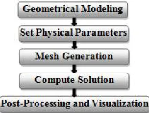
The fiber has been modeled by COMSOL, following steps are followed in order (Fig. 2):
Fig. 2. Flowchart for modeling of PCF in COMSOL Multiphysics.
freefree
t
r
D
t
r
B
J
t
t
r
D
t
r
H
t
t
r
B
t
r
E
,
0
,
,
,
)
,
(
,
…(5)For our model of optical fiber, we will assume that the fiber consists entirely of homogenous dielectric material. Also, it is assumed that no sources of light exist inside the fiber, so that no free charges or currents exist inside the fiber .
An electromagnetic wave can be expressed in terms of an electric field vector
E
and a magnetic field vectorB
. When incident on a material the termsH
, the magnetic flux density,D
the electric displacement vector,J
the current density and
the charge density are also defined.B. Finite Element Method (FEM)
The Finite Element Method (FEM) is a numerical technique for finding approximate solutions of partial differential equations as well as integral equations. This method approximates the PDE (Partial Differential Equation) as a system of ordinary differential equations which can be solved separately using various numerical techniques.
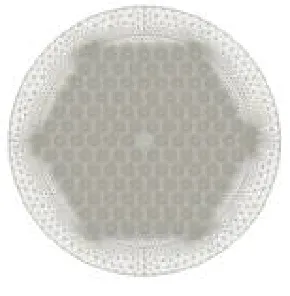
It sub-divides the object into very small but finite size elements. This process is called ‘meshing’ and is shown in Fig. 3 for the solid-core PCF. Each element of the mesh is governed by a set of characteristic equations which describe its physical properties and boundary conditions. These equations are then solved as a set of simultaneous equations to compute the effective index of the modes supported by the fiber [12].
Fig. 3. Solid-core PCF with triangular meshing
V. SIMULATIONS AND RESULTS
The finite element method (FEM) has been used for the modal analysis of a solid-core photonic crystal fiber formed by six rings structure with a hexagonal arrangement of circular air holes on the cladding of pure silica.
Vol. 5, Issue 9, September 2016
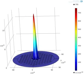
Fig. 4. Intensity profile of the proposed PCF design.
A. Effective refractive index
The effective refractive index is seen to be following a general decreasing trend to increasing wavelength (Fig.5). A maximum of neff 1.4427 was observed at wavelength 1.47 m and a minimum of neff 1.442 was observed at wavelength 1.63 m. For PCF designs with diameter of holes equal 4 m, the cladding refractive index depends on optical intensity distribution. The effective refractive index of the SC-PCF lies between the refractive index of the core and the cladding and it’s very close to the refractive index of the core. As wavelength increases the effects of diffraction become more important and the light spreads slightly into the cladding so the effective refractive index decreases towards the refractive index of the cladding.
Fig. 5. Effective index versus Wavelength ()
B. Chromatic Dispersion
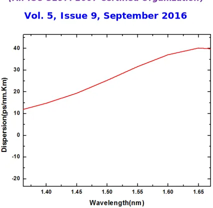
Material dispersion has shown a linear relationship with wavelength (Fig.6). PCFs considered as a high dispersive media over a broad wavelength this due to large index difference between the core and the cladding. The total dispersion can be calculated through eq.2, waveguide dispersion has been calculated from eq.4 by using the real part of refractive index as a function of wavelength while the material dispersion was calculated from eq.3.
Fig. 6. Chromatic dispersion versus Wavelength ().
C. Effective Mode Area
Effective area exhibits a generally increasing trend to increasing wavelength. A minimum effective area of 5.56*10-10 m2 was obtained at 1.47 m and a maximum of 5.617*10-10 m2 was obtained at 1.63 m. As wavelength increases, power density decreases and hence the effective area increases. It can be seen that Fig.7 does follow this trend.
Fig. 7. Effective area versus Wavelength ()
D. Nonlinear Coefficient
Vol. 5, Issue 9, September 2016
VI.CONCLUSION
We have simulated a s SC-PCF type ESM with six ring hexagonal geometry using finite element method. Numerical results of the effective index, chromatic dispersion, effective mode area, and nonlinear coefficient of the fiber are presented and compared with those in the literature. Numerical simulations have shown that the results of the finite element method are in a very good agreement with those in the literature.
REFERENCES
1- Lizier, J., “Applications of Holey Fiber Splicing, Spot-size conversion and Coupling”, School of Electrical and Information Engineering, University of Sydney, Sydney, Australia, (2000).
2- Poli, F.; Cucinotta, A.; Selleri, S., “ Photonic Crystal Fibers : Properties and Applications”, springer publisher, 1st edition, (2007).
3- Joannopolous, J.; Villeneuve, P.; Fan,S., "Photonic Crystals: putting a new twist on light", review article, Nature , vol. 386, pp. 143-149, (1997). 4- Libori, Stig E., “Photonic crystal fibers: from theory to practice”, Ph D Thesis, Technical University of Denmark, Kongens Lyngby, Denmark,
(2002).
5- Cerqueira, S. Arismar, “Recent progress and novel applications of photonic crystal fibers”, Reports on Progress in Physics, vol. 73, no. 2, Article ID 024401, (2010).
6- Finazzi, V.; Monri, T.; Richardson, D.; “ the role of confinement loss in highly nonlinear silica holey fibers”, IEEE photonics Technology Letters, Vol.15, no.9, pp. 1246-1248, (2003).
7- Agrwal. G., “Fiber optic communication system”, 3rd edition, John Wiley and Sons, INC. Publications, (2002).
8- Birks, T.; Mogilevtsev, D.; Knight, J.; Russell, Ph., “Dispersion compensation using single material fibers”, IEEE photonics Technology Letters, Vol.11, No.6, pp.674-676, (1999).
9- Wong, G. K. L.,“Non liner optics in photonic crystal fiber”, MS.c thesis, University of Auckland. USA, (2003)
10- Anand N.; Sudheer S.K.; Pillai, V.P., “Design and Analysis of a Non Linear, Low Confinement Loss Photonic Crystal Fiber with Liquid Crystal and Air filled holes”, 4th International Workshop on Fiber Optics in Access Network (FOAN), (2013).
11- Sharma, A.; and Chauhan, H., “A new analytical model for the field of microstructured optical fibers”, Optical and Quantum Electronic, vol. 41, pp. 235-242, (2009).